EP2065621A2 - Filtre fluide pour transmission automatique et procédé d'installation pour celui-ci - Google Patents
Filtre fluide pour transmission automatique et procédé d'installation pour celui-ci Download PDFInfo
- Publication number
- EP2065621A2 EP2065621A2 EP20080168366 EP08168366A EP2065621A2 EP 2065621 A2 EP2065621 A2 EP 2065621A2 EP 20080168366 EP20080168366 EP 20080168366 EP 08168366 A EP08168366 A EP 08168366A EP 2065621 A2 EP2065621 A2 EP 2065621A2
- Authority
- EP
- European Patent Office
- Prior art keywords
- case member
- valve body
- filter
- automatic transmission
- supporting frame
- Prior art date
- Legal status (The legal status is an assumption and is not a legal conclusion. Google has not performed a legal analysis and makes no representation as to the accuracy of the status listed.)
- Withdrawn
Links
- 239000012530 fluid Substances 0.000 title claims abstract description 123
- 230000005540 biological transmission Effects 0.000 title claims description 98
- 238000009434 installation Methods 0.000 title claims description 41
- 238000000034 method Methods 0.000 title claims description 25
- 230000002093 peripheral effect Effects 0.000 claims abstract description 137
- 239000011347 resin Substances 0.000 claims abstract description 21
- 229920005989 resin Polymers 0.000 claims abstract description 21
- 229910052751 metal Inorganic materials 0.000 description 16
- 239000002184 metal Substances 0.000 description 16
- 239000000463 material Substances 0.000 description 11
- 230000009467 reduction Effects 0.000 description 8
- 230000000694 effects Effects 0.000 description 7
- 238000003466 welding Methods 0.000 description 5
- XEEYBQQBJWHFJM-UHFFFAOYSA-N Iron Chemical compound [Fe] XEEYBQQBJWHFJM-UHFFFAOYSA-N 0.000 description 4
- 229910052782 aluminium Inorganic materials 0.000 description 4
- XAGFODPZIPBFFR-UHFFFAOYSA-N aluminium Chemical compound [Al] XAGFODPZIPBFFR-UHFFFAOYSA-N 0.000 description 4
- 230000005489 elastic deformation Effects 0.000 description 4
- 229920001971 elastomer Polymers 0.000 description 4
- 239000005060 rubber Substances 0.000 description 4
- 238000007789 sealing Methods 0.000 description 4
- 230000001747 exhibiting effect Effects 0.000 description 3
- 150000002739 metals Chemical class 0.000 description 3
- 229910052742 iron Inorganic materials 0.000 description 2
- 238000000465 moulding Methods 0.000 description 2
- -1 aluminum and iron Chemical class 0.000 description 1
- 238000005516 engineering process Methods 0.000 description 1
- 239000000835 fiber Substances 0.000 description 1
- 238000004519 manufacturing process Methods 0.000 description 1
- 239000004745 nonwoven fabric Substances 0.000 description 1
- 238000005192 partition Methods 0.000 description 1
- 239000013585 weight reducing agent Substances 0.000 description 1
- 239000002759 woven fabric Substances 0.000 description 1
Images


Classifications
-
- F—MECHANICAL ENGINEERING; LIGHTING; HEATING; WEAPONS; BLASTING
- F16—ENGINEERING ELEMENTS AND UNITS; GENERAL MEASURES FOR PRODUCING AND MAINTAINING EFFECTIVE FUNCTIONING OF MACHINES OR INSTALLATIONS; THERMAL INSULATION IN GENERAL
- F16H—GEARING
- F16H57/00—General details of gearing
- F16H57/04—Features relating to lubrication or cooling or heating
- F16H57/0402—Cleaning of lubricants, e.g. filters or magnets
- F16H57/0404—Lubricant filters
Definitions
- the present invention relates to fluid filters for automatic transmissions and an installation method for the same, and in particular, relates to fluid filters for automatic transmissions that enable cost reductions by reducing the number of parts, enable a simple installation irrespective of the material, shape or the like of a valve body, and enable further improvement of the reliability of the seal, and an installation method for the same.
- a conventional fluid filter for an automatic transmission that is generally known is one in which a filter element is disposed inside a filter chamber that is formed between an upper case and a lower case, and an outlet pipe that is provided in the upper case is inserted into a discharge outlet that is formed in a valve body with an O-ring interposed therebetween (refer, for example, to Patent Document 1).
- the conventional fluid filter for an automatic transmission is mainly structured by three parts, that is, the upper case, the lower case, and the filter element, and thus, there are many parts and the cost becomes high.
- a fluid filter for an automatic transmission has been proposed in which the upper case is omitted, and the fluid filter is structured by two main parts: a lower case, which is directly installed on the valve body, and a filter element (refer, for example, to Patent Documents 2 and 3).
- Patent Document 2 discloses, for example, a fluid filter for an automatic transmission in which a filter medium 111 is interposed between a flange of a cover member 103 that is integrally formed on a resin valve body 102 and a flange of a resin base member 104 (lower case), and vibration welded (refer to paragraph [0020] in Patent Document 2).
- Patent Document 3 discloses, for example, a fluid filter for an automatic transmission provided with a filter element 110 that is formed by integrating a filter medium 111, a flat metal frame 113, and a resin frame 112.
- the outer peripheral edge of the metal frame 113 of the filter element 110 is folded back and crimped onto a flange of a lower body 104 (lower case), and the metal frame 113 and the lower body 104 are fastened by bolts 116 to the valve body 102 (refer, for example, to paragraphs [0019] and [0020], and FIG. 1 of Patent Document 3).
- Patent Document 2 because the valve body and the base member are integrated by using vibration welding, a valve body that is generally made of aluminum must be changed to one that is made of resin. Moreover, the shape of the valve body must be significantly modified, and therefore, in the present situation, this fluid filter for an automatic transmission cannot be easily implemented by vehicle manufactures that manufacture automatic transmissions that include valve bodies. Furthermore, a process in which the valve body and the base member are subject to vibration welding is necessary. Therefore, even if the number of parts is reduced, the number of processes cannot be reduced, and thus there are also limits to the cost reductions.
- Patent Document 3 because a filter element is used that is formed by integrating the filter medium, the metal frame, and the resin frame, the filter element and thus the fluid filter for an automatic transmission become comparatively expensive. Furthermore, because sealing is carried out by using a flat metal frame, in order to increase the reliability of the seal, it is necessary to fasten the metal frame securely to the valve body by using a large number of bolts, and thus the installation operation becomes complicated.
- the present invention is as follows.
- the upper case is eliminated and the case member is installed on the valve body by the bolt, the locking hook or the like, and thus, in comparison to a conventional fluid filter in which the valve body and the case member are integrated by using vibration welding, it is possible to realize a reduction in costs by reducing the number of parts and the number of processes, and it is possible to install the fluid filter for an automatic transmission easily irrespective of the material, shape or the like of the valve body.
- the fluid filter for an automatic transmission of the present invention is provided with a seal member that is in pressure contact with the surface of the inner peripheral side of the upper end portion of the peripheral wall of the case member, the surface of the outer peripheral side of the upper end portion of the supporting frame, and the surface of the valve body.
- the space between the case member and the supporting frame is maintained in a fluid-tight state due to the seal member, and it is possible to prevent contaminated fluid from flowing into the clean side without passing through the filter medium.
- the space between the case member and the valve body is maintained in an air-tight state, and it is possible to prevent air from being drawn into the filter chamber. Therefore, in comparison to a conventional fluid filter in which sealing is carried out by using a flat metal frame, it is possible to improve the reliability of the seal without requiring a complicated installation operation.
- the seal member is disposed in the notched portion that is formed on at least one side among the inner peripheral side of the upper end portion of the peripheral wall of the case member and the outer peripheral side of the upper end portion of the supporting frame, the seal member is positioned inside the notched portion, and thus it is possible to prevent the misalignment of the seal member when installing the case member on the valve body.
- the case member, the filter element, and the seal member are integrated due to the press fitting of the press fitting portion of the seal member into the predetermined space, and thus it is possible to install the fluid filter for an automatic transmission more easily on the valve body.
- the handling characteristics during transport, storing and the like of the fluid filter for an automatic transmission are superior.
- the case member has the locking hook and the elastic supporting frame, accompanying the elastic deformation of the elastic supporting portions, the case member is installed in the valve body due to the locking of the locking hook into the locking portion that is provided in the valve body. Therefore, it is possible to install the fluid filter for an automatic transmission more easily on the valve body.
- the upper case is eliminated, and the case member is installed on the valve body by using bolts, locking hooks or the like, and thus, in comparison to a conventional fluid filter in which a valve body and a case member are integrated by using vibration welding, it is possible to realize a reduction in costs by reducing the number of parts and the number of processes, and in addition, it is possible to install the fluid filter for an automatic transmission easily irrespective of the material, shape and the like of the valve body.
- the filter element that has the filter medium and the supporting frame is used, and thus, in comparison to a conventional fluid filter that uses a filter element that is formed by integrating a filter medium, a metal frame, and a resin frame, it is possible to realize further cost reductions of the filter element and thus the fluid filter for an automatic transmission.
- the seal member is provided that is in pressure contact with the surface of the inner peripheral side of the upper end portion of the peripheral wall of the case member, the surface of the outer peripheral side of the upper end portion of the supporting frame, and the surface of the valve body, and thus the space between the case member and the supporting frame is maintained in a fluid-tight state by the seal member, it is possible to prevent contaminated fluid from flowing into the clean side without passing through the filter medium, and in addition, the space between the case member and the valve body is maintained in an air-tight state, and it is possible to prevent air from being drawn into the filter chamber. Therefore, in comparison to a conventional fluid filter in which sealing is carried out by a flat metal frame, it is possible to improve the reliability of the seal without requiring a complicated installation operation.
- a fluid filter for an automatic transmission according to a first embodiment is provided with a case member, a filter element, and a seal member, which will be described below.
- the structure, shape, material and the like of the "case member” described above are not particularly limited provided that the case member is installed on a valve body in which fluid paths are formed and forms the filter chamber in cooperation with the valve body.
- the material for the case member include resins and metals such as aluminum and iron. Among these, a resin is preferable in terms of weight reduction.
- examples of the material for the valve body include metals such as aluminum and iron, and resins. Among these, a metal is preferable in terms of high strength and high precision.
- the case member may have, for example, installation portions (for example, female screw portions or holes or the like) for bolts that are screwed into the valve body.
- the case member preferably includes locking hooks that lock to locking portions that are provided in the valve body and elastic support portions that elastically support these locking hooks.
- the structure, shape, layout and the like of the "filter element” described above are not particularly limited provided that the filter element is disposed inside the filter chamber and that it includes a filter medium and a resin supporting frame that supports the outer peripheral edge of the filter medium.
- the shape of this filter medium include pleated shape, a sheet shape, a wave shape, and a bag shape.
- examples of the material for the filter medium include a non-woven fabric, a woven fabric, paper and the like.
- the filter element described above can be formed, for example, by integrally molding the filter medium and the supporting frame by using insert molding.
- seal member is in pressure contact with the inner peripheral side of the upper end portion of the peripheral wall of the case member, the outer peripheral side of the upper end portion of the supporting frame, and the valve body.
- seal member examples include an O-ring, a V-ring, an irregular-shaped ring and the like.
- material for the seal member include rubbers, resins, metals and the like.
- examples of the fluid filter for an automatic transmission described above include a configuration in which the seal member is disposed in a notched portion that is formed on at least one side among an inner peripheral side of an upper end portion of the peripheral wall of the case member and an outer peripheral side of an upper end portion of the supporting frame (refer to FIG 2 ).
- the filter element can be disposed inside the filter chamber such that an upper end surface of the peripheral wall of the case member and an upper end surface of the supporting frame are set at substantially identical height levels.
- a seal member that has a comparatively simple structure, such as an O-ring.
- the supporting frame can be fit into and fastened to the inner peripheral side of the peripheral wall of the case member. Because the filter element and the case member are integrated due to the fitting attachment, it is possible to install the fluid filter for an automatic transmission more easily on the valve body.
- the seal member can be disposed by being press fit into the notched portion. Because the case member, the filter element, and the seal member are integrated due to the press fit disposition, it is possible to install the fluid filter for an automatic transmission more easily on the valve body. In addition, the handling characteristics during transport, storing or the like of the fluid filter for an automatic transmission are superior.
- examples of the fluid filter for an automatic transmission include a configuration in which the supporting frame is fit in the inner peripheral side of the peripheral wall of the case member with a predetermined space, and the seal member has a press fitting portion that is press fit into the predetermined space (refer to FIG. 5 and FIG. 7 ).
- the press fitting portion can be provided, for example, over the entire periphery of the seal member. Thereby, it is possible to maintain the fluid-tight state between the case member and the supporting frame more reliably.
- Examples of the press fitting portion include a configuration (1) in which the press fitting portion is formed into a plate shape that extends downward from the main seal portion (refer to FIG.
- the press fitting portion in configuration (2), can preferably be locked to the locking portion that is formed at the outer peripheral side of the upper end portion of the supporting frame. This is because the press fitting portion is easily press fit into the predetermined space between the case member and the supporting frame.
- the filter element can be disposed inside the filter chamber such that the upper end surface of the peripheral wall of the case member and the upper end surface of the supporting frame are set at substantially identical height levels.
- a seal member that has a comparatively simple structure.
- An installation method for the fluid filter for an automatic transmission according to a second embodiment includes a first step and a second step that will be described below.
- the disposition order, timing and the like of the "first step” are not limited in particular provided that the first step is a step in which a filter element that has a filter medium and a supporting frame that supports the outer peripheral edge of the filter medium is disposed inside the case member and the seal member is disposed between the inner peripheral side of the upper end portion of the peripheral wall of the case member and the outer peripheral side of the upper end portion of the supporting frame.
- the order of the disposition of the filter element and the disposition of the seal member is not limited in particular, and the disposition of both the filter element and the seal member may be carried out substantially simultaneously. Note that, for example, the structures of the members that have been explained in the first embodiment described above can be used as the filter element, the case member, and the seal member.
- examples of the first step described above include a configuration in which, first, the filter element is disposed inside the case member, and subsequently the seal member is disposed in the notched portion that is formed on at least one side among the inner peripheral side of the upper end portion of the peripheral wall of the case member and the outer peripheral side of the upper end portion of the supporting frame (refer to FIG. 2 ).
- the seal member is positioned in the notched portion, it is possible to install the fluid filter for an automatic transmission more easily on the valve body.
- the filter element is disposed inside the case member, and it is possible to set the upper end surface of the peripheral wall of the case member and the upper end surface of the supporting frame at substantially identical height levels.
- a seal member that has a comparatively simple structure, such as an O-ring.
- examples of the first step described above include the following two configurations.
- configuration (1) first, the seal member is disposed in a positioning portion that is formed on the inner peripheral side of the upper end portion of the peripheral wall of the case member, and subsequently, the filter element is disposed inside the case member by fitting the supporting frame in the inner peripheral side of the peripheral wall of the case member with a predetermined space, and the press fitting portion of the seal member is press fit into the predetermined space (refer to FIG. 6 ).
- the seal member is disposed in a positioning portion that is formed on the outer peripheral side of the upper end portion of the supporting frame, and subsequently, the filter element is disposed inside the case member by fitting the supporting frame in the inner peripheral side of the peripheral wall of the case member with a predetermined space, and the press fitting portion of the seal member is press fit into the predetermined space (refer to FIG. 8 ).
- the positioning portion include, for example, the notched portion into which the seal member is inserted or press fit, the locking portion by which the seal member can be locked, and the like.
- the second step is a step in which the case member is installed on the valve body in which fluid paths are formed and the seal member is in press contact with the valve body. Due to this second step, the seal member is crimped onto the surface of the inner peripheral side of the upper end portion of the peripheral wall of the case member, the surface of the outer peripheral side of the upper end potion of the supporting frame, and the surface of the valve body.
- the second step may be a step in which, for example, the case member is fastened by bolts to the valve body via installation portions (for example, a female screw portion, a hole portion, or the like) that are provided in the case member, but in terms of enabling the improvement of the installation characteristics of the fluid filter for an automatic transmission, the second step is preferably a step in which the case member is installed on the valve body by the locking of locking hooks that are elastically supported by the case member in the locking portions that are provided in the valve body.
- installation portions for example, a female screw portion, a hole portion, or the like
- the fluid filter 1A for an automatic transmission is provided with a resin case member 4 that is installed on an aluminum valve body 2 (refer to FIG 3 ) that has a plurality of fluid paths (not illustrated) formed therein, and form a filter chamber 3 in cooperation with the valve body 2.
- the case member 4 includes a bottom wall 5 in which an inlet 5a for fluid is formed and a peripheral wall 6 that rises from an outer peripheral edge of the bottom wall 5.
- a plurality of installation portions 7 for receiving the installation bolts 16 are provided on an outer peripheral side of an upper end portion of the peripheral wall 6.
- spool valves (not illustrated) are provided in the fluid paths of the valve body 2, and clutches of the automatic transmission are switched in response to the switching of the fluid paths by the spool valves.
- a filter element 10 that partitions the filter chamber 3 into an upper clean side 3a and a lower contaminated side 3b is disposed inside the filter chamber 3.
- the filter element 10 is formed by integrating a pleated non-woven fiber filter medium 11 and a resin supporting frame 12 that supports an outer peripheral edge side of the filter medium 11.
- the supporting frame 12 is fit into and fastened to a step shaped portion 6a that is formed on an inner peripheral side of the peripheral wall 6 of the case member 4.
- an upper end surface of the supporting frame 12 and an upper end surface of the peripheral wall of the case member 4 are set at substantially identical height levels.
- Beveled notched portions 13 are respectively formed on an inner peripheral side of the upper end portion of the peripheral wall 6 of the case member 4 and an outer peripheral side of the upper end portion of the supporting frame 12.
- the seal member 15 is in pressure contact with the surface of the notched portion 13 of the peripheral wall 6 of the case member, the surface of the notched portion 13 of the supporting frame 12, and the surface of the valve body 2 (refer to FIG. 3 ). Therefore, the space between the case member 4 and the supporting frame 12 is maintained in a fluid-tight state by the seal member 15, and at the same time, the space between the case member 4 and the valve body 2 is maintained in an air-tight state.
- the filter element 10 is disposed inside the case member 4 by fitting and fixing the supporting frame 12 to the inner peripheral side of the peripheral wall 6 of the case member 4, and the upper end surface of the peripheral wall 6 of the case member 4 and the upper end surface of the supporting frame 12 are set at substantially identical height levels.
- the seal member 15 is press fit into and disposed in the notched portions 13 that are formed in the peripheral wall 6 of the case member 4 and the supporting frame 12.
- the upper end surface of the peripheral wall 6 of the case member 4 and the upper end surface of the supporting frame 12 are set on an installation surface of the valve body 2 so as to cover a discharge outlet 2a of the valve body 2, and the seal member 15 is in pressure contact with valve body 2. Subsequently, the case 4 is fastened by the bolts 16 to the valve body 2 via the installation portions 7 of the case member 4, and thereby the fluid filter 1A for an automatic transmission is installed.
- the upper case is eliminated, and the case 4 is installed on the valve body 2 by being fastened by the bolts 16. Therefore, in comparison to the conventional fluid filter in which the valve body and the case member are integrated by using vibration welding, it is possible to reduce the cost by reducing the number of parts and the number of processes, and in addition, it is possible to install the fluid filter 1A for an automatic transmission easily irrespective of the material, shape or the like of the valve body 2.
- the filter element 10 that is formed by integrating the filter medium 11 and the supporting frame 12 is used. Therefore, in comparison to the conventional fluid filter in which a filter element is used that is formed by integrating the filter medium, the metal frame, and the resin frame, it is possible to realize further cost reductions of the filter element 10 and thus the fluid filter 1A for an automatic transmission
- the seal member 15 is provided that is in pressure contact with the surface of the inner peripheral side of the upper end portion of the peripheral wall 6 of the case member 4, the surface of the outer peripheral side of the upper end portion of the supporting frame 12, and the surface of the valve body 2. Therefore, the space between the case member 4 and the supporting frame 12 is maintained in a fluid-tight state by this seal member 15, and it is possible to prevent contaminated fluid from flowing to the clean side 3a without passing through the filter medium 11. In addition, the space between the case member 4 and the valve body 2 is maintained in an air-tight state, and it is possible to prevent air from being drawn into the filter chamber 3. Therefore, in comparison to carrying out the conventional sealing by using a flat metal frame, it is possible to improve the reliability of the seal without requiring a complicated installation operation.
- the filter element 10 is disposed inside the filter chamber 3 such that the upper end surface of the peripheral wall 6 of the case member 4 and the upper end surface of the supporting frame 12 are set at substantially identical height levels, and thus it is possible to use a seal member that has a comparatively simple structure, such as an O-ring, as the seal member 15.
- the supporting frame 12 is fit into and fastened to the inner peripheral side of the peripheral wall 6 of the case member 4, and the seal member 15 is press fit and disposed inside the notched portions 13 that are formed in the peripheral wall 6 of the case member 4 and the supporting frame 12, and thus, it is possible to integrate the case member 4, the filter element 10, and the seal member 15, and it is possible to install the fluid filter 1A for an automatic transmission on the valve body 2 more easily. In addition, it is possible to prevent the misalignment of the seal member 15 when installing the case member 4 onto the valve body 2. Furthermore, the handling characteristics during transport, storing or the like of the fluid filter 1A for an automatic transmission are superior.
- a locking hook 17 that is locked onto a stepped locking portion 2b that is provided in the valve body 2 and an elastic supporting portion 18 that elastically support the locking hook 17 is provided on the outer peripheral side of the upper end portion of the peripheral wall 6 of the case member 4.
- the filter element 10 is disposed inside the case member 4, and the upper end surface of the peripheral wall 6 of the case member 4 and the upper end surface of the supporting frame 12 are set at substantially identical height levels.
- the seal member 15 is inserted into each of the notched portions 13 that are formed in the peripheral wall 6 of the case member 4 and the supporting frame 12.
- the upper end surface of the peripheral wall 6 of the case member 4 and the upper end surface of the supporting frame 12 are set on the installation surface of the valve body 2 so as to cover the discharge outlet 2a of the valve body 2, and the seal member 15 is in pressure contact with the valve body 2.
- the locking hook 17 is locked by being inserted into the locking portion 2b of the valve body 2, the case member 4 is installed on the valve body 2, and thereby the fluid filter 1B for an automatic transmission is installed.
- the case member 4 is installed on the valve body 2 by the locking hook 17, and thus it is possible to install the fluid filter 1B for an automatic transmission more easily on the valve body 2.
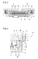
- the supporting frame 12 that constitutes the filter element 10 is fit into the predetermined space S in the inner peripheral side of the peripheral wall 6 of the case member 4.
- a rectangular notched portion 20 is formed on the inner peripheral side of the upper end portion of the peripheral wall 6 of the case member 4.
- a rubber seal member 21 is disposed inside the notched portion 20.
- this seal member 21 includes a main seal member 21a that is in press contact with the surface of the inner peripheral side of the upper end portion of the peripheral wall 6 of the case member 4, the surface of the outer peripheral side of the upper end portion of the supporting frame 12, and the surface of the valve body 2, and a press fitting portion 21b that is flat and extends downward from the main seal portion 21a, and is press fit into the predetermined space S.
- the press fitting portion 21b is provided on the entire periphery of the main seal member 21a.
- the seal member 21 is disposed inside the notched portion 20 that is formed in the peripheral wall 6 of the case member 4.
- the filter element 10 is disposed inside the case member 4 by fitting the supporting frame 12 into the predetermined space S on the inner peripheral side of the peripheral wall 6 of the case member 4.
- the upper end surface of the peripheral wall 6 of the case member 4 and the upper end surface of the supporting frame 12 are set at substantially identical height levels, and the press fitting portion 21b of the seal member 21 is press fit into the predetermined space S.
- the upper end surface of the peripheral wall 6 of the case member 4 and the upper end surface of the supporting frame 12 are set on the installation surface of the valve body 2 so as to cover the discharge outlet 2a of the valve body 2, and the main seal portion 21a of the seal member 21 is in pressure contact with the valve body 2.
- the locking hook 17 is locked by being inserted into the locking portion 2b of the valve body 2, the case member 4 is installed on the valve body 2, and thus the fluid filter 1C for an automatic transmission is installed.
- the case member 4, the filter element 10, and the seal member 21 are integrated due to the press fitting of the press fitting portion 21b of the seal member 21 into the predetermined space S, and thus it is possible to install the fluid filter 1C for an automatic transmission more easily on the valve body 2.
- the handling characteristics during transport, storing or the like of the fluid filter 1C for an automatic transmission are superior.
- the press fitting portion 21b is provided over the entire periphery of the main seal member 21a, and thus it is possible to further increase the reliability of the seal by the seal member 21.
- fluid filter for an automatic transmission according to a fourth embodiment will be explained. Note that in the fluid filter for an automatic transmission according to the fourth embodiment, structural components that are substantially identical to those of the fluid filters 1A and 1B for an automatic transmission according to the first and second embodiments have identical reference numerals appended thereto, and the detailed explanations thereof are omitted.
- the supporting frame 12 that constitutes the filter element 10 is fit into the predetermined space S in the inner peripheral side of the peripheral wall 6 of the case member 4.
- the upper end portion of the supporting frame 12 forms a locking portion 23 by being angled toward the outside.
- a rubber seal member 24 is formed by a main seal portion 24a that is in pressure contact with the surface of the inner peripheral side of the upper end portion of the peripheral wall 6 of the case member 4, the surface of the outer peripheral side of the upper end portion of the supporting frame 12, and the surface of the valve body 2, and a press fitting portion 24b having a substantially L-shape in longitudinal cross-section that is linked downward from the main seal portion 24a, and can be locked to the locking portions 23.
- the press fitting portion 24b is provided over the entire periphery of the main seal portion 24a.
- the press fitting portion 24b is press fit into the predetermined space S described above.
- the press fitting portion 24b of the seal member 24 is locked on the locking portion 23 of the supporting frame 12.
- the filter element 10 is disposed inside the case member 4 by fitting the supporting frame 12 in the inner peripheral side of the peripheral wall 6 of the case member 4 with the predetermined space S.
- the upper end surface of the peripheral wall 6 of the case member 4 and the upper end surface of the supporting frame 12 are set at substantially identical height levels, and the press fitting portion 24b of the seal member 24 is press fit into the predetermined space S.
- the upper end surface of the peripheral wall 6 of the case member 4 and the upper end surface of the supporting frame 12 are set on the installation surface of the valve body 2 so as to cover the discharge outlet 2a of the valve body 2, and the main seal portion 24a of the seal member 24 is in pressure contact with the valve body 12.
- the locking hook 17 is locked by being inserted into the locking portion 2b of the valve body 2, the case member 4 is installed on the valve body 2, and thereby the fluid filter 1D for an automatic transmission is installed.
- the case member 4, the filter element 10, and the seal member 24 are integrated due to the press fitting of the press fitting portion 24b of the seal member 24 into the predetermined space S, and thus it is possible to install the fluid filter 1D for an automatic transmission more easily on the valve body 2.
- the handling characteristics during transport, storing or the like of the fluid filter 1D for an automatic transmission are superior.
- the press fitting portion 24b is provided over the entire periphery of the main seal portion 24a, and thus it is possible to further increase the reliability of the seal by the seal member 24.
- the filter element 10 is disposed inside the filter chamber 3 such that the upper end surface of the peripheral wall 6 of the case member 4 and the upper end surface of the supporting frame 12 are set at substantially identical height levels.
- the present invention is not limited to this, and, for example, the filter element 10 may be disposed inside the filter chamber 3 such that the upper end surface of the peripheral wall 6 of the case member 4 and the upper end surface of the supporting frame 12 are set at differing height levels.
- the supporting frame 12 is fit into and fastened to the inner peripheral side of the peripheral wall 6 of the case member 4.
- the present invention is not limited to this, and, for example, the supporting frame 12 may be fit in the inner peripheral side of the peripheral wall 6 of the case member 4 with the predetermined space.
- the filter element 10 and the case member 4 are integrated by press fitting and disposing the seal member 15 into the notched portions 13.
- the present invention is not limited to this, and, for example, the seal member 15 may be positioned only in a horizontal direction by being inserted and disposed in the notched portions 13.
- the locking hook 17 and the elastic supporting portion 18 are provided on the case member 4.
- the present invention is not limited to this, and, for example, installation portions 7 for installation bolts (refer to FIG. 2 ) may be provided on the case member 4.
- the installation portion 7, the locking hook 17, and the elastic supporting portion 18 may be provided in combination on the case member 4.
- the notched portion 20, in which the seal member 21 is disposed is provided in the case member 4.
- the present invention is not limited to this, and, for example, a locking portion in which the seal member 21 is locked may be provided on the case member 4.
- a fluid filter is provided with: a case member that is installed on a valve body in which fluid paths are formed and forms a filter chamber in cooperation with the valve body; a filter element that is disposed in the filter chamber and includes a filter medium and a resin supporting frame that supports the outer peripheral edge of the filter medium; and a seal member that is in pressure contact with the surface of the inner peripheral side of the upper end portion of the peripheral wall of the case member, the surface of the outer peripheral side of the upper end portion of the supporting frame, and the surface of the valve body.
Landscapes
- Engineering & Computer Science (AREA)
- General Engineering & Computer Science (AREA)
- Mechanical Engineering (AREA)
- General Details Of Gearings (AREA)
- Arrangement Of Transmissions (AREA)
Applications Claiming Priority (1)
| Application Number | Priority Date | Filing Date | Title |
|---|---|---|---|
| JP2007306389A JP4968018B2 (ja) | 2007-11-27 | 2007-11-27 | 自動変速機用流体フィルタ及びその組付方法 |
Publications (2)
| Publication Number | Publication Date |
|---|---|
| EP2065621A2 true EP2065621A2 (fr) | 2009-06-03 |
| EP2065621A3 EP2065621A3 (fr) | 2010-07-21 |
Family
ID=40429932
Family Applications (1)
| Application Number | Title | Priority Date | Filing Date |
|---|---|---|---|
| EP20080168366 Withdrawn EP2065621A3 (fr) | 2007-11-27 | 2008-11-05 | Filtre fluide pour transmission automatique et procédé d'installation pour celui-ci |
Country Status (3)
| Country | Link |
|---|---|
| US (1) | US20090134088A1 (fr) |
| EP (1) | EP2065621A3 (fr) |
| JP (1) | JP4968018B2 (fr) |
Families Citing this family (4)
| Publication number | Priority date | Publication date | Assignee | Title |
|---|---|---|---|---|
| JP5336045B2 (ja) * | 2007-01-10 | 2013-11-06 | 株式会社ニフコ | 燃料用フィルタ装置 |
| DE102007023641B4 (de) * | 2007-05-22 | 2015-04-02 | Ibs Filtran Kunststoff-/ Metallerzeugnisse Gmbh | Ölfiltervorrichtung |
| JP5609237B2 (ja) | 2010-04-26 | 2014-10-22 | トヨタ紡織株式会社 | 自動変速機用流体フィルタ |
| JP6265200B2 (ja) * | 2015-07-29 | 2018-01-24 | 株式会社デンソー | サクションフィルタ及び燃料供給装置 |
Citations (3)
| Publication number | Priority date | Publication date | Assignee | Title |
|---|---|---|---|---|
| JPH084886A (ja) | 1994-06-23 | 1996-01-12 | Nok Corp | 自動変速装置用流体フィルタ装置 |
| JPH10272312A (ja) | 1997-03-28 | 1998-10-13 | Piolax Inc | オイルストレーナ |
| JP2004052820A (ja) | 2002-07-16 | 2004-02-19 | Toyo Roki Mfg Co Ltd | バルブボディ一体型フィルタ及びその製造方法 |
Family Cites Families (13)
| Publication number | Priority date | Publication date | Assignee | Title |
|---|---|---|---|---|
| US4388187A (en) * | 1981-04-27 | 1983-06-14 | Eaglestone Dustin D | Fuel filter |
| US4692245A (en) * | 1985-05-14 | 1987-09-08 | Parker Hannifin Corporation | Filter assembly with high pressure connection to collection bowl |
| US4764275A (en) * | 1985-10-25 | 1988-08-16 | Robichaud Arthur W | Fluid filter and method for attaching same in sealing relation to a filter mount |
| US5045192A (en) * | 1986-06-03 | 1991-09-03 | Facet Enterprises, Inc. | Filter assembly with lockable lug means |
| GB2222534B (en) * | 1988-09-09 | 1992-11-25 | Process Scient Innovations | Filter assembly and cartridge therefor |
| JPH0612288Y2 (ja) * | 1988-10-03 | 1994-03-30 | エヌオーケー株式会社 | 自動変速装置用流体フィルタ装置 |
| JPH0344262A (ja) * | 1989-07-12 | 1991-02-26 | Mitsubishi Electric Corp | イメージスキャナ装置 |
| US5035797A (en) * | 1990-02-14 | 1991-07-30 | Stanadyne Automotive Corp. | Key system for filter assembly |
| JP3502729B2 (ja) * | 1996-09-12 | 2004-03-02 | 株式会社 マーレ テネックス | オイルストレーナ |
| US5988399A (en) * | 1997-12-23 | 1999-11-23 | Baldwin Filters, Inc. | Spin-on filter |
| JP3556118B2 (ja) * | 1999-03-02 | 2004-08-18 | ダイハツ工業株式会社 | オイルストレーナの取付構造 |
| US6328883B1 (en) * | 2000-05-31 | 2001-12-11 | Parker-Hannifin Corporation | Fuel filter assembly with priming pump |
| JP4905128B2 (ja) * | 2006-12-29 | 2012-03-28 | トヨタ紡織株式会社 | 菊花型エレメント及びその製造方法並びに濾過体及び流体フィルタ |
-
2007
- 2007-11-27 JP JP2007306389A patent/JP4968018B2/ja not_active Expired - Fee Related
-
2008
- 2008-10-30 US US12/261,427 patent/US20090134088A1/en not_active Abandoned
- 2008-11-05 EP EP20080168366 patent/EP2065621A3/fr not_active Withdrawn
Patent Citations (3)
| Publication number | Priority date | Publication date | Assignee | Title |
|---|---|---|---|---|
| JPH084886A (ja) | 1994-06-23 | 1996-01-12 | Nok Corp | 自動変速装置用流体フィルタ装置 |
| JPH10272312A (ja) | 1997-03-28 | 1998-10-13 | Piolax Inc | オイルストレーナ |
| JP2004052820A (ja) | 2002-07-16 | 2004-02-19 | Toyo Roki Mfg Co Ltd | バルブボディ一体型フィルタ及びその製造方法 |
Also Published As
| Publication number | Publication date |
|---|---|
| US20090134088A1 (en) | 2009-05-28 |
| EP2065621A3 (fr) | 2010-07-21 |
| JP4968018B2 (ja) | 2012-07-04 |
| JP2009127819A (ja) | 2009-06-11 |
Similar Documents
| Publication | Publication Date | Title |
|---|---|---|
| JP5111494B2 (ja) | ろ過された側の流路に逆止弁を備えた液体フィルタ | |
| CN101991985B (zh) | 用于过滤流体的过滤器系统的密封装置 | |
| US6182693B1 (en) | Vapor canister and fuel tank assembly | |
| AU2012308622B2 (en) | Enhanced filter support basket | |
| CN102671448B (zh) | 液体过滤器的过滤器元件以及液体过滤器 | |
| EP2065621A2 (fr) | Filtre fluide pour transmission automatique et procédé d'installation pour celui-ci | |
| JP2008291683A (ja) | リッド分離型容器 | |
| US6340093B1 (en) | Fuel tank | |
| MXPA02008660A (es) | Filtro de liquidos, en particular un filtro de aceite. | |
| US20040086331A1 (en) | Attaching structure for valve device | |
| CA2582816A1 (fr) | Soupape de decharge a filtre, et joint d'etancheite pour cartouche filtrante | |
| US7294163B1 (en) | Cartridge filter | |
| EP2379196B1 (fr) | Illet d'étanchéité pour filtres à fluide | |
| US6955755B2 (en) | Liquid filter comprising a valve arranged in a support tube of a filter element | |
| US6338506B1 (en) | Evaporation valve pipe-fastening structure | |
| US20050077231A1 (en) | Oil filter gasket with flap | |
| JP2006214440A (ja) | 流体の流量を制御するバイパスバルブ、該バイパスバルブを含んで構成される流体フィルタ、該流体フィルタに用いられる媒体パック、及び、流体の濾過方法、並びに、流体のフィルタシステム | |
| US6189716B1 (en) | Secondary sealing of a fuel tank | |
| CN101939071A (zh) | 流体过滤器用底支承部和安全阀端密封部的单件式弹性组合件 | |
| CN113251706A (zh) | 一种蒸发器 | |
| MX2008000853A (es) | Placa de sujecion para asegurar un componente. | |
| US20230114490A1 (en) | Fuel device assemblies and vehicles including same for mounting a fuel baffle plate | |
| US20080006573A1 (en) | Exchangeable filter | |
| JP5483972B2 (ja) | 燃料タンク内部品の取付構造 | |
| JP4823609B2 (ja) | オイルストレーナ |
Legal Events
| Date | Code | Title | Description |
|---|---|---|---|
| PUAI | Public reference made under article 153(3) epc to a published international application that has entered the european phase |
Free format text: ORIGINAL CODE: 0009012 |
|
| 17P | Request for examination filed |
Effective date: 20081105 |
|
| AK | Designated contracting states |
Kind code of ref document: A2 Designated state(s): AT BE BG CH CY CZ DE DK EE ES FI FR GB GR HR HU IE IS IT LI LT LU LV MC MT NL NO PL PT RO SE SI SK TR |
|
| AX | Request for extension of the european patent |
Extension state: AL BA MK RS |
|
| PUAL | Search report despatched |
Free format text: ORIGINAL CODE: 0009013 |
|
| AK | Designated contracting states |
Kind code of ref document: A3 Designated state(s): AT BE BG CH CY CZ DE DK EE ES FI FR GB GR HR HU IE IS IT LI LT LU LV MC MT NL NO PL PT RO SE SI SK TR |
|
| AX | Request for extension of the european patent |
Extension state: AL BA MK RS |
|
| AKX | Designation fees paid |
Designated state(s): DE FR GB |
|
| 17Q | First examination report despatched |
Effective date: 20150427 |
|
| GRAP | Despatch of communication of intention to grant a patent |
Free format text: ORIGINAL CODE: EPIDOSNIGR1 |
|
| INTG | Intention to grant announced |
Effective date: 20170223 |
|
| STAA | Information on the status of an ep patent application or granted ep patent |
Free format text: STATUS: THE APPLICATION IS DEEMED TO BE WITHDRAWN |
|
| 18D | Application deemed to be withdrawn |
Effective date: 20170706 |