EP2065643B1 - Verbrennungssystem, Verfahren zur Umgestaltung eines Verbrennungssystems und Kraftstoffeinspritzverfahren für Verbrennungssysteme - Google Patents
Verbrennungssystem, Verfahren zur Umgestaltung eines Verbrennungssystems und Kraftstoffeinspritzverfahren für Verbrennungssysteme Download PDFInfo
- Publication number
- EP2065643B1 EP2065643B1 EP08020536.2A EP08020536A EP2065643B1 EP 2065643 B1 EP2065643 B1 EP 2065643B1 EP 08020536 A EP08020536 A EP 08020536A EP 2065643 B1 EP2065643 B1 EP 2065643B1
- Authority
- EP
- European Patent Office
- Prior art keywords
- fuel
- combustor
- combustors
- igniter
- pipe
- Prior art date
- Legal status (The legal status is an assumption and is not a legal conclusion. Google has not performed a legal analysis and makes no representation as to the accuracy of the status listed.)
- Active
Links
Images




Classifications
-
- F—MECHANICAL ENGINEERING; LIGHTING; HEATING; WEAPONS; BLASTING
- F23—COMBUSTION APPARATUS; COMBUSTION PROCESSES
- F23R—GENERATING COMBUSTION PRODUCTS OF HIGH PRESSURE OR HIGH VELOCITY, e.g. GAS-TURBINE COMBUSTION CHAMBERS
- F23R3/00—Continuous combustion chambers using liquid or gaseous fuel
- F23R3/42—Continuous combustion chambers using liquid or gaseous fuel characterised by the arrangement or form of the flame tubes or combustion chambers
- F23R3/46—Combustion chambers comprising an annular arrangement of several essentially tubular flame tubes within a common annular casing or within individual casings
- F23R3/48—Flame tube interconnectors, e.g. cross-over tubes
-
- F—MECHANICAL ENGINEERING; LIGHTING; HEATING; WEAPONS; BLASTING
- F02—COMBUSTION ENGINES; HOT-GAS OR COMBUSTION-PRODUCT ENGINE PLANTS
- F02C—GAS-TURBINE PLANTS; AIR INTAKES FOR JET-PROPULSION PLANTS; CONTROLLING FUEL SUPPLY IN AIR-BREATHING JET-PROPULSION PLANTS
- F02C3/00—Gas-turbine plants characterised by the use of combustion products as the working fluid
- F02C3/14—Gas-turbine plants characterised by the use of combustion products as the working fluid characterised by the arrangement of the combustion chamber in the plant
-
- F—MECHANICAL ENGINEERING; LIGHTING; HEATING; WEAPONS; BLASTING
- F02—COMBUSTION ENGINES; HOT-GAS OR COMBUSTION-PRODUCT ENGINE PLANTS
- F02C—GAS-TURBINE PLANTS; AIR INTAKES FOR JET-PROPULSION PLANTS; CONTROLLING FUEL SUPPLY IN AIR-BREATHING JET-PROPULSION PLANTS
- F02C7/00—Features, components parts, details or accessories, not provided for in, or of interest apart form groups F02C1/00 - F02C6/00; Air intakes for jet-propulsion plants
- F02C7/22—Fuel supply systems
- F02C7/228—Dividing fuel between various burners
-
- F—MECHANICAL ENGINEERING; LIGHTING; HEATING; WEAPONS; BLASTING
- F02—COMBUSTION ENGINES; HOT-GAS OR COMBUSTION-PRODUCT ENGINE PLANTS
- F02C—GAS-TURBINE PLANTS; AIR INTAKES FOR JET-PROPULSION PLANTS; CONTROLLING FUEL SUPPLY IN AIR-BREATHING JET-PROPULSION PLANTS
- F02C7/00—Features, components parts, details or accessories, not provided for in, or of interest apart form groups F02C1/00 - F02C6/00; Air intakes for jet-propulsion plants
- F02C7/26—Starting; Ignition
- F02C7/264—Ignition
-
- F—MECHANICAL ENGINEERING; LIGHTING; HEATING; WEAPONS; BLASTING
- F23—COMBUSTION APPARATUS; COMBUSTION PROCESSES
- F23K—FEEDING FUEL TO COMBUSTION APPARATUS
- F23K5/00—Feeding or distributing other fuel to combustion apparatus
- F23K5/02—Liquid fuel
- F23K5/06—Liquid fuel from a central source to a plurality of burners
-
- F—MECHANICAL ENGINEERING; LIGHTING; HEATING; WEAPONS; BLASTING
- F23—COMBUSTION APPARATUS; COMBUSTION PROCESSES
- F23N—REGULATING OR CONTROLLING COMBUSTION
- F23N1/00—Regulating fuel supply
- F23N1/002—Regulating fuel supply using electronic means
-
- F—MECHANICAL ENGINEERING; LIGHTING; HEATING; WEAPONS; BLASTING
- F23—COMBUSTION APPARATUS; COMBUSTION PROCESSES
- F23N—REGULATING OR CONTROLLING COMBUSTION
- F23N5/00—Systems for controlling combustion
- F23N5/20—Systems for controlling combustion with a time program acting through electrical means, e.g. using time-delay relays
- F23N5/203—Systems for controlling combustion with a time program acting through electrical means, e.g. using time-delay relays using electronic means
-
- F—MECHANICAL ENGINEERING; LIGHTING; HEATING; WEAPONS; BLASTING
- F05—INDEXING SCHEMES RELATING TO ENGINES OR PUMPS IN VARIOUS SUBCLASSES OF CLASSES F01-F04
- F05D—INDEXING SCHEME FOR ASPECTS RELATING TO NON-POSITIVE-DISPLACEMENT MACHINES OR ENGINES, GAS-TURBINES OR JET-PROPULSION PLANTS
- F05D2260/00—Function
- F05D2260/85—Starting
-
- F—MECHANICAL ENGINEERING; LIGHTING; HEATING; WEAPONS; BLASTING
- F23—COMBUSTION APPARATUS; COMBUSTION PROCESSES
- F23D—BURNERS
- F23D2209/00—Safety arrangements
- F23D2209/30—Purging
-
- F—MECHANICAL ENGINEERING; LIGHTING; HEATING; WEAPONS; BLASTING
- F23—COMBUSTION APPARATUS; COMBUSTION PROCESSES
- F23N—REGULATING OR CONTROLLING COMBUSTION
- F23N2225/00—Measuring
- F23N2225/26—Measuring humidity
-
- F—MECHANICAL ENGINEERING; LIGHTING; HEATING; WEAPONS; BLASTING
- F23—COMBUSTION APPARATUS; COMBUSTION PROCESSES
- F23N—REGULATING OR CONTROLLING COMBUSTION
- F23N2227/00—Ignition or checking
- F23N2227/02—Starting or ignition cycles
-
- F—MECHANICAL ENGINEERING; LIGHTING; HEATING; WEAPONS; BLASTING
- F23—COMBUSTION APPARATUS; COMBUSTION PROCESSES
- F23N—REGULATING OR CONTROLLING COMBUSTION
- F23N2227/00—Ignition or checking
- F23N2227/04—Prepurge
-
- F—MECHANICAL ENGINEERING; LIGHTING; HEATING; WEAPONS; BLASTING
- F23—COMBUSTION APPARATUS; COMBUSTION PROCESSES
- F23N—REGULATING OR CONTROLLING COMBUSTION
- F23N2237/00—Controlling
- F23N2237/02—Controlling two or more burners
Definitions
- the present invention relates to a combusting system, a remodeling method for the combusting system, and a fuel injection method for the combusting system.
- Patent Publication 1 discloses a gas turbine including multiple combustors.
- gas turbines of the type including multiple combustors are each configured such that all adjacent combustors disposed annularly along the perimeter of the gas turbine are fluidly connected to one another through a cross fire tube.
- the cross fire tube allows combustion gases to flow through the inside thereof by making use of the inter-combustor pressure difference.
- one or two combustors are each provided with a ignitor that generates electrical spark.
- ignition fuel-air ratio the ratio between fuel and air necessary for ignition
- cross fire ignition thermal energy of combustion gases entering from the adjacent combustor
- spark plug ignition the ratio between fuel and air necessary for ignition
- US 5 402 635 A describes a combustor having a coupling for a cross-flame tube.
- the coupling has inner and outer sleeves that form an annular passage therebetween. Holes in the outer sleeve place the annular passage in flow communication with cooling air in the combustion system chamber, thereby causing the cooling air to flow over the proximal end of the outer sleeve.
- a baffle is formed on the inner sleeve and has a pattern of raised and depressed areas. The raised areas form lands that are attached to the combustor wall. The depressed areas form passages with the wall that direct the cooling air from the annular passage so that it flows over the surface of the combustor inner wall, thereby preventing over heating of the wall.
- EP 0 962 704 A2 describes an apparatus for use in a system having a gas fuel supply and a combustor including a fuel actuator, a controller, and a premixer.
- the controller generates a command signal indicative of actuation sought from the fuel actuator for example in response to pressure variations in the combustor as measured by a sensor.
- the actuator receives gas fuel from the liquid fuel supply and provides liquid fuel at a modulated rate of flow in response to the command signal.
- the premixer receives the fuel from the actuator, mixes the fuel with air, and provides the mixture to the combustor.
- the present invention is to improve reliability and environmental performance of a combusting system including multiple combustors.
- the present invention provides a combusting system according to claim 1. Further, a remodeling method for a combusting system according to claim 7 and a fuel injection method for a combusting system according to claim 8 are provided.
- the dependent claims refer to preferred embodiments of the invention.
- a combusting system including a plurality of combustors each including a fuel pipe that supplies fuel to a fuel nozzle, and a fuel purge system connected to the fuel pipe, wherein adjacent ones of the plurality of combustors are interconnected through a cross fire tube, and some of the plurality of combustors each include a ignitor; and a device for delaying fuel injection from the combustion nozzle of the combustor including the ignitor from fuel injection from the combustion nozzle of the combustor not including the ignitor.
- a combusting system including a plurality of combustors each including a fuel pipe that supplies fuel to a fuel nozzle that injects the fuel, and a fuel purge system connected to the fuel pipe, wherein adjacent ones of the plurality of combustors are interconnected through a cross fire tube, and some of the plurality of combustors each include a ignitor.
- a volume of a flow passage of the fuel flowing through the fuel pipe extending from a connection portion between the fuel pipe and the fuel purge system to a discharge portion that discharges purged fuel to the outside in the combustor including the ignitor is greater than the volume of a flow passage of the fuel flowing through the fuel pipe in the identical section in the combustor not including the ignitor.
- a combusting system including a plurality of combustors each including a fuel pipe that supplies fuel to a fuel nozzle, a fuel purge system that discharges the fuel residual in the fuel pipe to an outside of the fuel pipe, and a connection portion between the fuel pipe and the fuel purge system, wherein adjacent ones of the plurality of combustors are interconnected through a cross fire tube, and some of the plurality of combustors each include a ignitor; and a flow divider that distributes fuel to a plurality of the pipes, the fuel being supplied from a fuel tank.
- a volume of a flow passage of the fuel flowing through the fuel pipe extending from a connection portion between the fuel pipe and the fuel purge system to a discharge portion that discharges a purged fuel to the outside in the combustor including the ignitor is greater than the volume of a flow passage of the fuel flowing through the fuel pipe in the identical section in the combustor not including the ignitor.
- the combusting system may further include a three-way valve provided upstream of a connection portion between the fuel pipe of and the fuel purge system of the combustor including the ignitor, wherein a tank for storing purged fuel is connected to one end of the three-way valve.
- each of the combustor including the ignitor and the combustor not including the ignitor may be a pilot burner of a diffusion combustion type, wherein a premixer is disposed on a circumference of the pilot burner.
- a combusting system including a plurality of combustors each including a fuel pipe that supplies fuel to a fuel nozzle, a fuel purge system that discharges the fuel residual in the fuel pipe to an outside of the fuel pipe, and a connection portion between the fuel pipe and the fuel purge system, wherein adjacent ones of the plurality of combustors are interconnected through a cross fire tube, and some of the plurality of combustors each include a ignitor; and a control valve and a control device that are provided midway of the fuel pipe in the combustor including the ignitor, the control valve being provided to regulate a fuel flow amount, and the control device being provided to perform on-off control of the control valve in accordance with atmospheric temperature and humidity.
- a remodeling method for a combusting system including a plurality of combustors each including a fuel pipe that supplies fuel to a fuel nozzle, and a fuel purge system that is connected to the fuel pipe and that discharges the fuel residual in the fuel pipe from the fuel pipe, wherein adjacent ones of the plurality of combustors are interconnected through a cross fire tube, and some of the plurality of combustors each include a ignitor.
- the remodeling method replaces the fuel pipe so that a volume of a flow passage of the fuel flowing through the fuel pipe extending from a connection portion between the fuel pipe and the fuel purge system to a discharge portion that discharges purged fuel to the outside in the combustor including the ignitor is greater than the volume of a flow passage of the fuel flowing through the fuel pipe in the identical section in the combustor not including the ignitor.
- a fuel injection method for a combusting system including a plurality of combustors each including an a fuel nozzle that injects fuel into a combustion chamber, wherein adjacent ones of the plurality of combustors are interconnected through a cross fire tube, and some of the plurality of combustors each include a ignitor.
- the fuel injection method includes a first step for starting injection of the fuel from the fuel nozzle of the combustor not including the ignitor; and a second step for starting injection of the fuel from the fuel nozzle of the combustor including the ignitor after the first step.
- the fuel injection method may further include a third step for causing ignition of the combustor not including the ignitor after the elapse of predetermined time period.
- the reliability of a combusting system including a plurality of combustors can be improved, and an environmental performance thereof can be improved.
- a first embodiment will be described herebelow with reference to FIGS. 1 to 4 and 8 .
- the present embodiment is an example of application to a gas turbine as a combusting system.
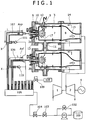
- FIG. 1 is a schematic configuration view showing the overall configuration of a gas turbine plant including gas turbine combustors of the first embodiment.
- the gas turbine plant primarily includes a compressor 1, multiple combustors 3a and 3b, and a turbine 2.
- the compressor 1 compresses air to thereby generate high pressure combustion air.
- the combustors 3a and 3b each mix a combustion air 14 and fuel introduced from the compressor 1.
- a turbine 2 receives a combustion gas 15 generated in the combustors 3a and 3b and introduced therefrom.
- FIG. 1 only two of ten cans or ten combustors (described further below) are representatively shown. Shafts of the compressor 1 and the turbine 2 fluidly connected to one another.
- Combustors 3a and 3b each include an outer casing 5 and an end cover 6 that hermetically enclose components including an combustor liner 7, a transition piece 8, a liquid fuel nozzle 10, a swirler 12, and a spark plug 9.
- the combustor liner 7 causes premixed combustion of the fuel and the combustion air 14 from the compressor 1.
- the transition piece 8 guides the combustion gas 15 generated in the combustor liner 7 to the turbine 2.
- the liquid fuel nozzle 10 is provided on an upstream side of the combustor liner 7, and atomizes the liquid fuel.
- the swirler 12 swirls the combustion air 14.
- the spark plug 9 serves as a ignitor that causes ignition in the combustor 3a.
- the combustion air 14 supplied from the compressor 1 travels through an airflow channel configured from the outer casing 5, the combustor liner 7, and the transition piece 8. Then, the combustion air 14 is introduced into the combustor liner 7 from, for example, a combustion air hole and cooling air hole provided in a wall face of the combustor liner 7 and an air hole provided in the swirler 12.
- the combustion air 14 and the fuel are mixed together into a gaseous mixture, and the gaseous mixture burns or combusts.
- the combustion gas 15 generated through combustion is injected into the turbine 2 through the transition piece 8, thereby to drive the turbine 2.
- a generator 4 fluidly connected to the turbine 2 is driven, thereby to perform power generation.
- a fuel supply system is configured to include a fuel tank 100, a fuel pump 101, a pressure regulating valve 102, a fuel shut-off valve 103, a flow control valve 104, and a flow divider 105.
- Fuel pipes 106 and 107 fluidly connecting to the respective combustors 3b and 3a are provided downstream of the flow divider 105.
- a fuel purge system for preventing coking phenomena occurrable in the fuel pipe and fuel nozzle is fluidly connected midway of the respective fuel pipe 106, 107.
- the fuel purge system is configured from a purge air compressor 108, a purge air shut-off valve 109, and respective check valve 110, 111.
- the liquid fuel is boosted by the fuel pump 101, and is set to a predetermined pressure through the pressure regulating valve 102 disposed in a bypass line of the fuel pump 101.
- the liquid fuel thus boosted is passed through the fuel shut-off valve 103 and the flow control valve 104 and is then distributed to the respective combustors through the flow divider 105. In this manner, the liquid fuel is supplied to the respective combustors 3a and 3b.
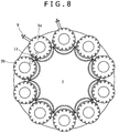
- gas turbine combustors which are configured from multiple cans, are disposed annularly along the circumferential direction of the turbine 2.
- FIG. 8 is a schematic view of the gas turbine combustors (shown in FIG. 1 ) in the case where an end cover 6 is viewed along a turbine rotation axis direction.
- the spark plug 9 is provided to each of two combustors.
- a ignitor spark plug
- combustors are configured from multiple cans
- components such as a fuel nozzle 10 and a swirler 12 are used so that the flow characteristic of the fuel nozzle 10 and the structure of the swirler 12 is identical in the respective combustor.
- FIG. 2 is a view showing the overall configurations of combustors, a fuel supply system, and a fuel purge system of a first comparative example.
- the fuel supply system in each of all the combustors is identical in cross-sectional area size, so that the cross-sectional area size of the respective fuel pipe 106, 107 fluidly connected to the respective combustor 3a, 3b is identical.
- the fuel purge system fluidly connected to the fuel pipe of the respective combustor 3a, 3b to discharge the liquid fuel into the combustor liner 7 is fluidly connected to an identical position (point X) spaced apart by L (length) from fuel supply inlet port of the fuel nozzle 10.
- Ignition operation in each of the combustors 3a and 3b (or expressed in such manner as "respective combustor 3a, 3b," herebelow) of the first comparative example configured as described above will be described herebelow.
- the compressor 1 is speeded up to a predetermined ignition rotation speed in response to external energy or, more specifically, a dynamo-electric motor electrical motor. Thereby, the combustion air 14 from the compressor 1 supplied to the combustors 3a and 3b. Thereafter, upon transmission of an ignition instruction signal, electrical sparking is started by the spark plug 9, and open operations of the fuel shut-off valve 103 and the flow control valve 104 are performed, whereby the fuel equally distributed by the flow divider 105 is supplied to the combustors 3a and 3b.
- ignition in the combustor 3a is effected by electrical sparking of the spark plug 9 (the ignition herebelow will be refer to as "spark plug ignition”), in which a flame 16 is formed.
- spark plug ignition in which a flame 16 is formed.
- the interior pressure of the combustor liner 7 abruptly increases, causing a pressure difference from that in the un-ignited combustor 3b.
- a high temperature combustion gas 17 flows through the cross fire tube 11 from the combustor 3a to the combustor 3b.
- ignition in the combustor 3b is effected with thermal energy of the high temperature combustion gas 17 (the ignition herebelow will be referred to as "cross fire ignition").
- the fuel residual in the fuel pipe 106, 107 and the fuel nozzle 10 is discharged with the purge air into the fuel nozzle 10 from the fuel inlet port of the fuel nozzle 10, as described above.
- the fuel nozzle inlet port corresponds to a discharge portion that discharges the purged fuel to the outside.
- the cross-sectional area size of the fuel passage of the fuel flowing through the fuel pipe and the pipe length to the fuel supply inlet ports of the fuel nozzles 10 from the connection portion (point X) is identical in the respective combustor 3a, 3b.
- the volume of purge air residual in the interior of the respective fuel pipe is caused to be identical after completion of fuel purge.
- the timing of fuel injection from the fuel nozzle 10 is identical in the respective the combustor.
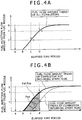
- FIG. 4A shows an elapsed time period of the fuel flow amount in the combustor 3a, 3b of the first comparative example.
- the horizontal axis indicates the elapsed time period
- the vertical axis indicates the fuel injection flow amount.
- a point A indicates a transmission point of the ignition instruction signal
- a point B indicates a fuel injection start point from the fuel nozzle 10
- a point G indicate a final reaching point in fuel injection amount at the ignition time.
- a point E indicates a fuel flow amount necessary for the spark plug ignition
- a point F indicates a fuel flow amount necessary for the cross fire ignition.
- the fuel flow amount necessary for ignition indicates characteristics that the amount for the cross fire ignition is greater (E ⁇ F) as compared with the amount for the spark plug ignition.
- Points C and D indicate reaching times (at the points E and F).
- liquid fuel or gas fuel is used as the fuel for supply to the combusting system.
- liquid fuel or gas fuel is used as the fuel for supply to the combusting system.
- uncombusted fuel is deposited on the inner side of the combustor liner.
- the liquid fuel deposited on the combustor liner is affected by heat, thereby to evaporate causing white smoke.
- White smoke produces smell, so that, for a combusting system installed in an urban area, it is important to prevent white smoke from occurring from the combusting system in consideration of peripheral environments.
- FIG. 3 shows a second comparative example including a premixer 21 that reduces the amount of NOx emissions (or "NOx emission amount,” herebelow).
- a pilot burner 19 of a diffusion combustion type that is excellent in combustion stability is disposed in the center of the combustor, in which the premixer 21 is disposed in the circumference thereof.
- the cross-sectional area size of a flow passage of the fuel flowing through the fuel pipe in the section extending to the discharge portion that discharges the purged fuel to the outside from the connection portion between the fuel pipe and the fuel purge system in the combustor including the ignitor is greater than the cross-sectional area size of a flow passage of the fuel flowing through the fuel pipe in the identical section in the combustor not including the ignitor.
- a cross-sectional area Asp of the fuel pipe 107 in the section extending to the fuel inlet port of the fuel nozzle 10 from the connection portion (point X) between the fuel purge system and the fuel pipe in the fuel supply system of the combustor 3a including the spark plug 9 is greater than an cross-sectional area size Axf of the fuel pipe 106 for the combustor 3b not including the spark plug.
- the distance to the fuel inlet port of the fuel nozzle 10 from the connection portion (point X) between the fuel purge system and the fuel pipe is identical for each of the combustor 3a including the spark plug 9 and the combustor 3b not including the spark plug.
- the fuel pipe 107 for the combustor 3a is greater than the fuel pipe 106 for the combustor 3b in the volume of the flow passage of the fuel flowing through the fuel pipe.
- the volume of the flow passage of the fuel is represented by the product of the multiplication between the length of the pipe and the cross-sectional area size of the flow passage of the fuel flowing through the pipe.
- the timing of injection of the fuel from the fuel nozzle 10 of the combustor 3a is set to be later as compared to that in the combustor 3b.
- FIG. 4B shows the transition of the fuel injection flow amount from the fuel nozzle 10 relative to the time variation in the event described above.
- the ignition instruction signal is transmitted at a point a.
- a time period from the point a to a point b is a time period until the fuel pipe 106 for the combustor 3b not including the spark plug is filled with the liquid fuel.
- the fuel is injected from the fuel nozzle 10 of the combustor 3b.
- the volume of the flow passage of the fuel flowing through the fuel pipe 107 is greater than in the case of the combustor 3b not including the spark plug.
- the time period until the fuel pipe 107 is filled with the liquid fuel is longer than that in the case of the combustor 3b, so that fuel injection is started at a point c.
- the flow characteristic of the fuel nozzle 10 in the respective combustor is identical.
- the rate of an increase in the fuel injection flow amount at and after the point c in the combustor 3a including the spark plug 9 is substantially the same as the rate of an increase in the fuel injection flow amount at and after the point b in the combustor 3b not including the spark plug.
- the present invention can be configured to include a device (means) for delaying a start time of fuel injection.
- the section delays a start time (point c) of fuel injection from a fuel nozzle included in a combustor including a ignitor from a start time (point b) of fuel injection from a fuel nozzle included in a combustor not including the ignitor.
- a device for delaying a start time of fuel injection.
- the section delays a start time (point c) of fuel injection from a fuel nozzle included in a combustor including a ignitor from a start time (point b) of fuel injection from a fuel nozzle included in a combustor not including the ignitor.
- the cross fire ignition can be stably effected, and the characteristics of the cross fire ignition can be improved in comparison to the comparative examples. Further, even with no nozzle provided to the fuel pipe extending from the flow divider 105 to a fuel nozzle 13, the fuel injection flow amount reaches the points substantially the same time (point d) in the combustor including the ignitor and the combustor not including the ignitor. Hence, control can be prevented from becoming complex.
- the length (L) to the fuel nozzle inlet port from the connection portion (point X) between the fuel pipe and the fuel purge system of the respective combustor is identical.
- the length (L) is identical in each of existing gas turbine combustors.
- the flow divider 105 for distributing the fuel is provided on the upstream side of the respective combustor 3a, 3b. Because of the flow divider 105 provided, the fuel tank does not have to be provided for the respective combustor, and fuel injection timing does not have to be regulated. Hence, the fuel supply system can be formed into a simple configuration.
- the fuel purge system for discharging the fuel resident in the fuel pipe into the fuel pipe in the event of stopping of fuel supply is fluidly connected to the fuel pipe (point X).
- the fuel resident in the interior of the respective fuel pipe 106, 107 and the fuel nozzle 10 is replaced with the purge air.
- the purge air enters the interiors of the respective fuel pipe 106, 107 on the side downstream of the connection portion (point X) between the fuel purge system and the fuel pipe.
- the volumes of the purge air entered the respective combustors 3a and 3b will be described.
- the start time of injection from the fuel nozzle 10 in the combustor 3a including the ignitor can be delayed from that in the combustor 3b not including the ignitor.
- the present embodiment of the present invention is effective for improving ignition properties even in gas turbine combustors including liquid fuel combustors in which start and stop operations are frequently performed.
- the discharge portion for discharging the purged fuel to the outside is the fuel inlet port of the fuel nozzle, and hence the purged fuel is discharged into the combustor liner 7.
- a storage tank for separately storing the purged fuel does not have to be provided, so that the cost can be reduced.
- the size of the cross-sectional area Asp can be changed.
- the fuel injection start time of the respective combustor 3a, 3b can be set to the cross fire ignition with optimal conditions, thereby enabling the improvement of the ignition properties.
- the size of the cross-sectional area Asp of the fuel pipe 107 including the ignitor is defined by using FIG. 4B .
- the volume level of the fuel necessary for the combustor 3b not including the spark plug to reach the point f which is shown in the figure, is represented by Fxf (portion surrounded by a single-dotted chain line in the figure).
- the volume level of the fuel necessary for the combustor 3a including the spark plug to reach the point e is represented by Fsp (boldly hatched portion in the figure).
- the cross-sectional area size of the fuel pipe 106 of the combustor 3b is represented Axf
- the length of the pipe extending to the fuel inlet port of the fuel nozzle 10 from the connection portion (point X) between the fuel pipe and the fuel purge system is represented by L.
- the start time of fuel injection from the fuel nozzle of the combustor including the ignitor is preferably delayed by a predetermined time period or more from the start time for starting fuel injection from the fuel nozzle of the combustor not including the ignitor. This is preferable to enable the ignition to be effected in the combustor 3b not including the ignitor at the free point d at which ignition failure does not occur.
- the combustors of the embodiment of the present invention is not only capable of acquiring the above-described effects as combustors mounted in a gas turbine newly installed, but is also capable of obtaining similar effects as combustors mounted in an existing gas turbine only by changing the fuel pipe 107 for the combustor 3a including the spark plug 9. Hence, the combustors are widely applicable.
- a second embodiment will be described with reference to FIG. 5 .
- connection portion (X point) between the fuel pipe and the fuel purge system is formed further upstream of the point X1.
- a length L2 of the fuel pipe 107 from a connection portion (point X2) of the fuel purge system of the combustor 3a including the spark plug 9 is designed to be longer than a length L1 of the fuel pipe 106 from a connection portion (point X1) of the fuel purge system of the combustor 3b not including the spark plug to the fuel nozzle inlet port.
- the volume of the fuel pipe 107 for the combustor 3a including the ignitor can be made to be greater than the volume of the fuel pipe 106 for the combustor 3b not including the ignitor, so that effects similar to those of the first embodiment can be expected.
- the cross-sectional area size of the fuel pipe 107 is enlarged midway of the flow passage and is reduced at the inlet port of the fuel nozzle 10. Hence, during the fuel purge after the gas turbine has stopped, the fuel can remain in the enlarged or reduced portion of the flow passage.
- the cross-sectional area size of the fuel pipe 107 is uniform in any portion, the fuel can be prevented from remaining therein during the fuel purge.
- combustors with even higher reliability can be provided.
- a third embodiment of the present invention will be described with reference to FIG. 6 .
- the cross-sectional area sizes of the fuel pipes 106 and 107 of all the combustors 3a and 3b are identical to one another.
- a difference from the second embodiment is that also the positions of connection of the fuel purge system to the fuel pipes are identical to one another.
- L3 be the distance from the connection portion between the fuel purge system and the fuel pipe to the fuel nozzle inlet port.
- a three-way valve 113 is provided only to the fuel pipe 107 of the combustor 3a including the spark plug 9 on an upstream side spaced apart by L4 (L3 ⁇ L4) from the fuel nozzle inlet port.
- a check valve 112 for preventing backflow to the flow divider 105 is provided upstream of the three-way valve 113, and further, one end of the three-way valve 113 (that is, the upstream side of the three-way valve 113) is fluidly connected to a purge fuel tank 114.
- the volume of the flow passage of the fuel flowing through the fuel pipe 107 extending to the fuel nozzle inlet port from the connection portion between the fuel purge system and the fuel pipe for the combustor 3a is set greater than the volume of the flow passage of the fuel flowing through the fuel pipe 106 in the identical portion for the combustor 3b.
- the purged fuel is deposited on, for example, the combustor liner 7 and the swirler 12, in which coking phenomena can occur to the extent of plugging cooling air holes of the combustor liner 7 and air holes of the swirler 12.
- the amount of the purged fuel discharging into the combustor liner 7 of the respective combustor 3a, 3b is as small as possible.
- the three-way valve 113 operates so that, after the gas turbine has stopped, the fuel pipe 107 in the section extending from the connection portion (point X3) between the fuel purge system and the fuel pipe 107 is fluidly connected to the three-way valve 113.
- the fuel residual in the fuel pipe 107 downstream of the connection portion (point X3) for the combustor 3a is discharged into the combustor liner of the combustor 3a, and the fuel residual on the side upstream of the connection portion (point X3) is discharged with the purge air into the purge fuel tank 114.
- two discharge portions for discharging the purged fuel are provided, in which one is the fuel nozzle inlet port and the other is the three-way valve 113.
- the volume of the flow passage of the fuel flowing through the fuel pipe extending from the connection portion between the fuel purge system and the fuel pipe can be caused to be smaller than that in the above-described embodiment.
- the purge air when the purge air is supplied, the amount of the fuel to be discharged into the combustor liner of the combustor 3a can be reduced, and hence the occurrence of exhaust smoke can be restrained, an environmentally friendly combusting system can be provided.
- effects similar to those of the first and second embodiments can be obtained, and hence a highly reliable combusting system can be provided.
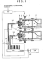
- Combustors of the present embodiment are similar to those of the each of the first to third embodiments, except that a control valve 115 is provided midway of the fuel pipe 107 for the combustor 3a including the spark plug 9.
- the volume of the flow passage of the fuel flowing through the fuel pipe 107 for the combustor 3a including the ignitor is set greater than the volume of the flow passage of the fuel flowing through the fuel pipe 106 for the combustor 3b not including the ignitor.
- the fuel injection timings in the respective combustors 3a and 3b are differentiated from one another.
- the amount of combustion air from the compressor 1 varies depending upon the conditions of, for example, atmospheric temperature and humidity.
- the fuel flow amount necessary for ignition is variable depending upon the conditions.
- the opening of the control valve 115 provided to the fuel pipe 107 for the combustor 3a including the ignitor and of the purge air shut-off valve 109 provided to fuel purge system, and the transmission timing of the ignition instruction signal are controlled in accordance with signals issued from a control device 200.
- the atmospheric temperature and humidity are input into the control device 200.
- the opening of the control valve 115 is controlled in accordance with the atmospheric temperature and humidity input into the control device 200. Further, also for the amount of air necessary for fuel purge, which is executed after the gas turbine has stopped, the opening of the purge air shut-off valve 109 is regulated by the control device 200.
- the combustor with even higher reliability in which the transmission timing of the ignition instruction signal and the operation of the control valve 115 are controlled to thereby enable the fuel injection timing to be optionally regulated without impairing the ignition properties even when the fuel flow amount necessary for ignition is variable depending upon, for example, atmospheric conditions.
- the present invention can be widely applied not only to gas turbine combustors but also to combusting systems each configured to include multiple combustors. Further, as the fuel to be used for the combusting system, any one of liquid fuel and gas fuel can be used.
Landscapes
- Engineering & Computer Science (AREA)
- Chemical & Material Sciences (AREA)
- Combustion & Propulsion (AREA)
- Mechanical Engineering (AREA)
- General Engineering & Computer Science (AREA)
- Feeding And Controlling Fuel (AREA)
- Nozzles For Spraying Of Liquid Fuel (AREA)
- Control Of Combustion (AREA)
- Pressure-Spray And Ultrasonic-Wave- Spray Burners (AREA)
Claims (8)
- Verbrennungssystem, das Folgendes umfasst:mehrere Brennkammern (3a, 3b), die jeweils eine Kraftstoffleitung (106, 107), die einer Kraftstoffdüse (10) Kraftstoff zuführt, und ein Kraftstoffreinigungssystem, das mit der Kraftstoffleitung (106, 107) verbunden ist, enthalten, wobei benachbarte Brennkammern der mehreren Brennkammern (3a, 3b) durch ein Kreuzfeuerrohr (11) miteinander verbunden sind und einige der mehreren Brennkammern (3a, 3b) jeweils einen Zünder (9) enthalten,gekennzeichnet durchMittel, um die Kraftstoffeinspeisung von der Verbrennungsdüse (10) der Brennkammer (3a) mit dem Zünder (9) im Vergleich zu der Kraftstoffeinspeisung von der Verbrennungsdüse (10) der Brennkammer (3b) ohne den Zünder (9) im Falle einer Zündung zu verzögern.
- Verbrennungssystem nach Anspruch 1, wobei
die Mittel darin bestehen, dass ein Volumen eines Strömungsdurchgangs des Kraftstoffs, der durch die Kraftstoffleitung (106, 107), die sich von einem Verbindungsabschnitt zwischen der Kraftstoffleitung (106, 107) und dem Kraftstoffreinigungssystem zu einem Förderabschnitt, der gereinigten Kraftstoff nach außen fördert, in der Brennkammer (3a) mit dem Zünder (9) erstreckt, strömt, größer ist als das Volumen eines Strömungsdurchgangs des Kraftstoffs, der durch die Kraftstoffleitung (106, 107) in dem identischen Abschnitt in der Brennkammer (3b) ohne den Zünder (9) strömt. - Verbrennungssystem nach Anspruch 2, das ferner Folgendes umfasst:einen Stromteiler (105), der Kraftstoff an mehrere der Leitungen verteilt, wobei der Kraftstoff von einem Kraftstofftank (100) zugeführt wird.
- Verbrennungssystem nach einem der Ansprüche 1-3, das ferner Folgendes umfasst:ein Dreiwegeventil (113), das stromaufwärts eines Verbindungsabschnitts zwischen der Kraftstoffleitung (106, 107) und dem Kraftstoffreinigungssystem der Brennkammer (3a) mit dem Zünder (9) vorgesehen ist, wobei ein Tank (114) zum Speichern gereinigten Kraftstoffs mit einem Ende des Dreiwegeventils (113) verbunden ist.
- Verbrennungssystem nach einem der Ansprüche 1-4, wobei die Kraftstoffdüse (10) sowohl in der Brennkammer (3a) mit dem Zünder (9) als auch in der Brennkammer (3b) ohne den Zünder (9) ein Zündbrenner (19) eines Diffusionsverbrennungstyps ist, wobei ein Vormischer (21) auf einem Umfang des Zündbrenners (19) angeordnet ist.
- Verbrennungssystem nach Anspruch 1, wobei
die Mittel ein Steuerventil (115) und eine Steuervorrichtung (200), die in der Mitte der Kraftstoffleitung (106, 107) in der Brennkammer (3a) mit dem Zünder (9) vorgesehen sind, enthalten, wobei das Steuerventil (115) vorgesehen ist, eine Kraftstoffstrommenge zu regulieren, und die Steuervorrichtung (200) vorgesehen ist, eine Ein/Aus-Steuerung des Steuerventils (115) gemäß atmosphärischer Temperatur und Feuchtigkeit durchzuführen. - Kraftstoffeinspeiseverfahren für ein Verbrennungssystem, das mehrere Brennkammern (3a, 3b), die jeweils eine Kraftstoffdüse (10), die Kraftstoff in eine Verbrennungskammer einspeist, enthalten, enthält, wobei benachbarte Brennkammern der mehreren Brennkammern (3a, 3b) durch ein Kreuzfeuerrohr (11) miteinander verbunden sind und einige der mehreren Brennkammern (3a, 3b) jeweils einen Zünder (9) enthalten, wobei das Kraftstoffeinspeiseverfahren Folgendes umfasst: einen ersten Schritt zum Starten der Einspeisung des Kraftstoffs von der Kraftstoffdüse (10) der Brennkammer (3b) ohne den Zünder (9); einen zweiten Schritt zum Starten der Einspeisung des Kraftstoffs von der Kraftstoffdüse (10) der Brennkammer (3a) mit dem Zünder (9) nach dem ersten Schritt; und einen dritten Schritt zum Bewirken einer Zündung der Brennkammer (3b) ohne den Zünder (9) nach Verstreichen eines vorgegebenen Zeitraums.
- Kraftstoffeinspeiseverfahren für ein Verbrennungssystem nach Anspruch 7, wobei das Verfahren die Kraftstoffleitung (106, 107) in der Weise ersetzt, dass ein Volumen eines Strömungsdurchgangs des Kraftstoffs, der durch die Kraftstoffleitung (106, 107), die sich von einem Verbindungsabschnitt zwischen der Kraftstoffleitung (106, 107) und dem Kraftstoffreinigungssystem zu einem Förderabschnitt, der gereinigten Kraftstoff nach außen fördert, in der Brennkammer (3a) mit dem Zünder (9) erstreckt, strömt, größer ist als das Volumen eines Strömungsdurchgangs des Kraftstoffs, der durch die Kraftstoffleitung (106, 107) in dem identischen Abschnitt in der Brennkammer (3b) ohne den Zünder (9) strömt.
Applications Claiming Priority (1)
| Application Number | Priority Date | Filing Date | Title |
|---|---|---|---|
| JP2007308160A JP4959523B2 (ja) | 2007-11-29 | 2007-11-29 | 燃焼装置,燃焼装置の改造方法及び燃焼装置の燃料噴射方法 |
Publications (3)
| Publication Number | Publication Date |
|---|---|
| EP2065643A2 EP2065643A2 (de) | 2009-06-03 |
| EP2065643A3 EP2065643A3 (de) | 2014-08-20 |
| EP2065643B1 true EP2065643B1 (de) | 2018-02-21 |
Family
ID=40394510
Family Applications (1)
| Application Number | Title | Priority Date | Filing Date |
|---|---|---|---|
| EP08020536.2A Active EP2065643B1 (de) | 2007-11-29 | 2008-11-26 | Verbrennungssystem, Verfahren zur Umgestaltung eines Verbrennungssystems und Kraftstoffeinspritzverfahren für Verbrennungssysteme |
Country Status (4)
| Country | Link |
|---|---|
| US (1) | US8082724B2 (de) |
| EP (1) | EP2065643B1 (de) |
| JP (1) | JP4959523B2 (de) |
| CN (1) | CN101446420B (de) |
Families Citing this family (33)
| Publication number | Priority date | Publication date | Assignee | Title |
|---|---|---|---|---|
| WO2008070210A2 (en) * | 2006-06-15 | 2008-06-12 | Indiana University Research And Technology Corporation | Pilot fuel injection for a wave rotor engine |
| WO2011089729A1 (ja) * | 2010-01-25 | 2011-07-28 | トヨタ自動車株式会社 | ガスタービンの制御装置及びガスタービンの始動方法 |
| JP5156066B2 (ja) * | 2010-08-27 | 2013-03-06 | 株式会社日立製作所 | ガスタービン燃焼器 |
| BR112013010886A2 (pt) | 2010-11-05 | 2016-08-02 | Thermochem Recovery Int Inc | sistema de circulação de sólidos e processo para captura e conversão de sólidos reativos |
| US8991188B2 (en) | 2011-01-05 | 2015-03-31 | General Electric Company | Fuel nozzle passive purge cap flow |
| US8893501B2 (en) * | 2011-03-28 | 2014-11-25 | General Eletric Company | Combustor crossfire tube |
| US8826667B2 (en) | 2011-05-24 | 2014-09-09 | General Electric Company | System and method for flow control in gas turbine engine |
| AU2012315914B2 (en) | 2011-09-27 | 2015-07-09 | Thermochem Recovery International, Inc. | System and method for syngas clean-up |
| US11015808B2 (en) | 2011-12-13 | 2021-05-25 | General Electric Company | Aerodynamically enhanced premixer with purge slots for reduced emissions |
| US8959925B2 (en) * | 2012-01-18 | 2015-02-24 | General Electric Company | Combustor recovery method and system |
| US20130305728A1 (en) * | 2012-05-15 | 2013-11-21 | General Electric Company | Systems and Methods for Minimizing Coking in Gas Turbine Engines |
| US9103284B2 (en) * | 2012-05-31 | 2015-08-11 | General Electric Company | Utilization of fuel gas for purging a dormant fuel gas circuit |
| JP5908379B2 (ja) * | 2012-09-24 | 2016-04-26 | 三菱日立パワーシステムズ株式会社 | ガスタービン燃焼器 |
| US9080772B2 (en) * | 2013-06-13 | 2015-07-14 | Delavan Inc | Continuous ignition |
| FR3021073B1 (fr) * | 2014-05-19 | 2019-06-07 | Safran Helicopter Engines | Architecture d'injection de carburant amelioree. |
| US10161635B2 (en) * | 2014-06-13 | 2018-12-25 | Rolls-Royce Corporation | Combustor with spring-loaded crossover tubes |
| JP6325930B2 (ja) * | 2014-07-24 | 2018-05-16 | 三菱日立パワーシステムズ株式会社 | ガスタービン燃焼器 |
| ES2940894T3 (es) | 2016-02-16 | 2023-05-12 | Thermochem Recovery Int Inc | Sistema y método de generación de gas producto de energía integrada de dos etapas |
| EP3433340B1 (de) | 2016-03-25 | 2022-06-29 | ThermoChem Recovery International, Inc. | Dreistufiges energieintegriertes produktgaserzeugungssystem |
| JP6612165B2 (ja) * | 2016-03-29 | 2019-11-27 | 三菱日立パワーシステムズ株式会社 | ガスタービン燃焼器 |
| US10526965B2 (en) | 2016-04-29 | 2020-01-07 | Rolls-Royce Corporation | Ignition system for constant volume combustor |
| KR102268593B1 (ko) * | 2016-07-01 | 2021-06-23 | 한화에어로스페이스 주식회사 | 슬링거 연소기 및 이를 구비한 가스 터빈 엔진 시스템 |
| JP6675280B2 (ja) * | 2016-07-05 | 2020-04-01 | 株式会社ガスター | パイロットバーナ、ガス燃焼装置 |
| US10364398B2 (en) | 2016-08-30 | 2019-07-30 | Thermochem Recovery International, Inc. | Method of producing product gas from multiple carbonaceous feedstock streams mixed with a reduced-pressure mixing gas |
| KR101867047B1 (ko) * | 2016-10-27 | 2018-06-14 | 두산중공업 주식회사 | 예혼합챔버를 포함하는 점화시스템을 갖춘 가스터빈 연소기. |
| US9920926B1 (en) | 2017-07-10 | 2018-03-20 | Thermochem Recovery International, Inc. | Pulse combustion heat exchanger system and method |
| US10099200B1 (en) | 2017-10-24 | 2018-10-16 | Thermochem Recovery International, Inc. | Liquid fuel production system having parallel product gas generation |
| US11486303B2 (en) * | 2019-05-15 | 2022-11-01 | Pratt & Whitney Canada Corp. | System and method for purging a fuel manifold of a gas turbine engine using a pump |
| US11680549B2 (en) * | 2019-10-04 | 2023-06-20 | Hamilton Sundstrand Corporation | Fluid injection systems for fluid line purging |
| US11555157B2 (en) | 2020-03-10 | 2023-01-17 | Thermochem Recovery International, Inc. | System and method for liquid fuel production from carbonaceous materials using recycled conditioned syngas |
| US11466223B2 (en) | 2020-09-04 | 2022-10-11 | Thermochem Recovery International, Inc. | Two-stage syngas production with separate char and product gas inputs into the second stage |
| JP7381659B2 (ja) * | 2021-09-30 | 2023-11-15 | 三菱重工業株式会社 | ガスタービン設備 |
| TWI880740B (zh) * | 2021-09-30 | 2025-04-11 | 日商三菱重工業股份有限公司 | 發電設備 |
Family Cites Families (20)
| Publication number | Priority date | Publication date | Assignee | Title |
|---|---|---|---|---|
| GB622904A (en) * | 1941-10-30 | 1949-05-10 | Power Jets Ltd | Fuel system |
| US2543366A (en) * | 1948-12-29 | 1951-02-27 | Rolls Royce | Two-position fuel valve for gasturbine torch igniters |
| US2722803A (en) * | 1951-05-23 | 1955-11-08 | Gen Electric | Cooling means for combustion chamber cross ignition tubes |
| US2979898A (en) * | 1958-04-25 | 1961-04-18 | United Aircraft Corp | Hooded crossover tube |
| US3001366A (en) * | 1958-05-15 | 1961-09-26 | Gen Motors Corp | Combustion chamber crossover tube |
| US3811274A (en) * | 1972-08-30 | 1974-05-21 | United Aircraft Corp | Crossover tube construction |
| US4249372A (en) * | 1979-07-16 | 1981-02-10 | General Electric Company | Cross-ignition assembly for combustion apparatus |
| JPH01294916A (ja) * | 1988-05-23 | 1989-11-28 | Toshiba Corp | ガスタービン燃料供給装置 |
| GB9021201D0 (en) * | 1990-09-28 | 1990-11-14 | Ruston Gas Turbines Ltd | Gas turbine combustors |
| JP3178055B2 (ja) * | 1992-01-13 | 2001-06-18 | 株式会社日立製作所 | ガスタービン燃焼器の制御装置及びガスタービン |
| US5402635A (en) * | 1993-09-09 | 1995-04-04 | Westinghouse Electric Corporation | Gas turbine combustor with cooling cross-flame tube connector |
| JPH10121986A (ja) * | 1996-10-24 | 1998-05-12 | Hitachi Ltd | ガスタービン及びその着火方法 |
| US6560967B1 (en) * | 1998-05-29 | 2003-05-13 | Jeffrey Mark Cohen | Method and apparatus for use with a gas fueled combustor |
| JP2000248964A (ja) * | 1999-02-26 | 2000-09-12 | Honda Motor Co Ltd | ガスタービンエンジン |
| JP3926075B2 (ja) * | 1999-11-29 | 2007-06-06 | 株式会社東芝 | ガスタービン燃焼器 |
| JP2005106344A (ja) * | 2003-09-29 | 2005-04-21 | Noritz Corp | 石油燃焼装置 |
| JP2006083730A (ja) * | 2004-09-15 | 2006-03-30 | Hitachi Ltd | ガスタービンの着火検出方法 |
| JP4659543B2 (ja) * | 2005-07-13 | 2011-03-30 | 株式会社日立製作所 | ガスタービン燃焼器、その燃料のカーボン化防止方法及びパージ方法 |
| JP2007155170A (ja) * | 2005-12-02 | 2007-06-21 | Hitachi Ltd | 燃料ノズル,ガスタービン燃焼器,ガスタービン燃焼器の燃料ノズル及びガスタービン燃焼器の改造方法 |
| GB2434437B (en) * | 2006-01-19 | 2011-01-26 | Siemens Ag | Improvements in or relating to combustion apparatus |
-
2007
- 2007-11-29 JP JP2007308160A patent/JP4959523B2/ja active Active
-
2008
- 2008-11-25 US US12/277,324 patent/US8082724B2/en active Active
- 2008-11-26 EP EP08020536.2A patent/EP2065643B1/de active Active
- 2008-11-27 CN CN2008101815540A patent/CN101446420B/zh active Active
Non-Patent Citations (1)
| Title |
|---|
| None * |
Also Published As
| Publication number | Publication date |
|---|---|
| CN101446420B (zh) | 2010-11-10 |
| US8082724B2 (en) | 2011-12-27 |
| US20090139241A1 (en) | 2009-06-04 |
| HK1130878A1 (en) | 2010-01-08 |
| EP2065643A2 (de) | 2009-06-03 |
| EP2065643A3 (de) | 2014-08-20 |
| JP2009133220A (ja) | 2009-06-18 |
| JP4959523B2 (ja) | 2012-06-27 |
| CN101446420A (zh) | 2009-06-03 |
Similar Documents
| Publication | Publication Date | Title |
|---|---|---|
| EP2065643B1 (de) | Verbrennungssystem, Verfahren zur Umgestaltung eines Verbrennungssystems und Kraftstoffeinspritzverfahren für Verbrennungssysteme | |
| US5121597A (en) | Gas turbine combustor and methodd of operating the same | |
| EP1106928B1 (de) | Verfahren zur gestuften Brennstoffzufuhr in zugleich mit flüssig- und gasförmigen Brennstoffen getriebenen Gasturbinen | |
| US7513100B2 (en) | Systems for low emission gas turbine energy generation | |
| US8763359B2 (en) | Apparatus for combusting fuel within a gas turbine engine | |
| JP4733195B2 (ja) | ガスタービンエンジンの燃料噴霧装置 | |
| EP2902708B1 (de) | Gasturbinenbrennkammer für mehrere brennstoffe | |
| US8375726B2 (en) | Combustor assembly in a gas turbine engine | |
| US6826913B2 (en) | Airflow modulation technique for low emissions combustors | |
| CN100552300C (zh) | 用于燃烧器的同心的固定稀释及可变的旁路空气喷射 | |
| EP0765453B1 (de) | Voreinspritzung für gasturbinenanlagen | |
| US8572977B2 (en) | Combustor of a gas turbine engine | |
| CN114008387A (zh) | 用于点燃器的第二级燃烧 | |
| JP5775319B2 (ja) | 軸方向多段予混合燃焼室 | |
| EP0680554A1 (de) | Steuervorrichtung für ein gasturbinentriebwerk | |
| RU97479U1 (ru) | Малоэмиссионная камера сгорания газотурбинного двигателя | |
| JP3996100B2 (ja) | ガスタービン用燃焼器及びその運転方法 | |
| EP2570730A2 (de) | System und Verfahren zur Steuerung der Verbrennungsinstabilitäten in Gasturbinensystemen | |
| JPH03144216A (ja) | ガスタービン燃焼器 | |
| JP2891020B2 (ja) | 燃焼器の制御装置 | |
| US20260117705A1 (en) | Attritable Torch Ignition System | |
| HK1130878B (en) | Combusting apparatus, remodeling method for combusting apparatus, and fuel injection method for combusting apparatus | |
| JP2006029237A (ja) | ガスタービン燃焼装置 |
Legal Events
| Date | Code | Title | Description |
|---|---|---|---|
| PUAI | Public reference made under article 153(3) epc to a published international application that has entered the european phase |
Free format text: ORIGINAL CODE: 0009012 |
|
| AK | Designated contracting states |
Kind code of ref document: A2 Designated state(s): AT BE BG CH CY CZ DE DK EE ES FI FR GB GR HR HU IE IS IT LI LT LU LV MC MT NL NO PL PT RO SE SI SK TR |
|
| AX | Request for extension of the european patent |
Extension state: AL BA MK RS |
|
| 17P | Request for examination filed |
Effective date: 20090512 |
|
| PUAL | Search report despatched |
Free format text: ORIGINAL CODE: 0009013 |
|
| AK | Designated contracting states |
Kind code of ref document: A3 Designated state(s): AT BE BG CH CY CZ DE DK EE ES FI FR GB GR HR HU IE IS IT LI LT LU LV MC MT NL NO PL PT RO SE SI SK TR |
|
| AX | Request for extension of the european patent |
Extension state: AL BA MK RS |
|
| RAP1 | Party data changed (applicant data changed or rights of an application transferred) |
Owner name: MITSUBISHI HITACHI POWER SYSTEMS, LTD. |
|
| RIC1 | Information provided on ipc code assigned before grant |
Ipc: F02C 7/228 20060101ALI20140711BHEP Ipc: F02C 3/14 20060101ALI20140711BHEP Ipc: F23N 1/00 20060101AFI20140711BHEP Ipc: F23N 5/20 20060101ALI20140711BHEP Ipc: F02C 7/264 20060101ALI20140711BHEP Ipc: F23K 5/06 20060101ALI20140711BHEP Ipc: F23R 3/48 20060101ALI20140711BHEP |
|
| RBV | Designated contracting states (corrected) |
Designated state(s): AT BE BG CH CY CZ DE DK EE ES FI FR GB GR HR HU IE IS IT LI LT LU LV MC MT NL NO PL PT RO SE SI SK TR |
|
| RAP1 | Party data changed (applicant data changed or rights of an application transferred) |
Owner name: MITSUBISHI HITACHI POWER SYSTEMS, LTD. |
|
| AKX | Designation fees paid |
Designated state(s): AT BE BG CH CY CZ DE DK EE ES FI FR GB GR HR HU IE IS IT LI LT LU LV MC MT NL NO PL PT RO SE SI SK TR |
|
| AXX | Extension fees paid |
Extension state: AL Extension state: RS Extension state: MK Extension state: BA |
|
| GRAP | Despatch of communication of intention to grant a patent |
Free format text: ORIGINAL CODE: EPIDOSNIGR1 |
|
| STAA | Information on the status of an ep patent application or granted ep patent |
Free format text: STATUS: GRANT OF PATENT IS INTENDED |
|
| INTG | Intention to grant announced |
Effective date: 20170901 |
|
| GRAS | Grant fee paid |
Free format text: ORIGINAL CODE: EPIDOSNIGR3 |
|
| GRAA | (expected) grant |
Free format text: ORIGINAL CODE: 0009210 |
|
| STAA | Information on the status of an ep patent application or granted ep patent |
Free format text: STATUS: THE PATENT HAS BEEN GRANTED |
|
| AK | Designated contracting states |
Kind code of ref document: B1 Designated state(s): AT BE BG CH CY CZ DE DK EE ES FI FR GB GR HR HU IE IS IT LI LT LU LV MC MT NL NO PL PT RO SE SI SK TR |
|
| REG | Reference to a national code |
Ref country code: GB Ref legal event code: FG4D |
|
| REG | Reference to a national code |
Ref country code: CH Ref legal event code: EP |
|
| REG | Reference to a national code |
Ref country code: AT Ref legal event code: REF Ref document number: 972161 Country of ref document: AT Kind code of ref document: T Effective date: 20180315 |
|
| REG | Reference to a national code |
Ref country code: IE Ref legal event code: FG4D |
|
| REG | Reference to a national code |
Ref country code: DE Ref legal event code: R096 Ref document number: 602008054065 Country of ref document: DE |
|
| REG | Reference to a national code |
Ref country code: NL Ref legal event code: MP Effective date: 20180221 |
|
| REG | Reference to a national code |
Ref country code: LT Ref legal event code: MG4D |
|
| REG | Reference to a national code |
Ref country code: AT Ref legal event code: MK05 Ref document number: 972161 Country of ref document: AT Kind code of ref document: T Effective date: 20180221 |
|
| PG25 | Lapsed in a contracting state [announced via postgrant information from national office to epo] |
Ref country code: NO Free format text: LAPSE BECAUSE OF FAILURE TO SUBMIT A TRANSLATION OF THE DESCRIPTION OR TO PAY THE FEE WITHIN THE PRESCRIBED TIME-LIMIT Effective date: 20180521 Ref country code: LT Free format text: LAPSE BECAUSE OF FAILURE TO SUBMIT A TRANSLATION OF THE DESCRIPTION OR TO PAY THE FEE WITHIN THE PRESCRIBED TIME-LIMIT Effective date: 20180221 Ref country code: FI Free format text: LAPSE BECAUSE OF FAILURE TO SUBMIT A TRANSLATION OF THE DESCRIPTION OR TO PAY THE FEE WITHIN THE PRESCRIBED TIME-LIMIT Effective date: 20180221 Ref country code: NL Free format text: LAPSE BECAUSE OF FAILURE TO SUBMIT A TRANSLATION OF THE DESCRIPTION OR TO PAY THE FEE WITHIN THE PRESCRIBED TIME-LIMIT Effective date: 20180221 Ref country code: CY Free format text: LAPSE BECAUSE OF FAILURE TO SUBMIT A TRANSLATION OF THE DESCRIPTION OR TO PAY THE FEE WITHIN THE PRESCRIBED TIME-LIMIT Effective date: 20180221 Ref country code: ES Free format text: LAPSE BECAUSE OF FAILURE TO SUBMIT A TRANSLATION OF THE DESCRIPTION OR TO PAY THE FEE WITHIN THE PRESCRIBED TIME-LIMIT Effective date: 20180221 Ref country code: HR Free format text: LAPSE BECAUSE OF FAILURE TO SUBMIT A TRANSLATION OF THE DESCRIPTION OR TO PAY THE FEE WITHIN THE PRESCRIBED TIME-LIMIT Effective date: 20180221 |
|
| PG25 | Lapsed in a contracting state [announced via postgrant information from national office to epo] |
Ref country code: BG Free format text: LAPSE BECAUSE OF FAILURE TO SUBMIT A TRANSLATION OF THE DESCRIPTION OR TO PAY THE FEE WITHIN THE PRESCRIBED TIME-LIMIT Effective date: 20180521 Ref country code: AT Free format text: LAPSE BECAUSE OF FAILURE TO SUBMIT A TRANSLATION OF THE DESCRIPTION OR TO PAY THE FEE WITHIN THE PRESCRIBED TIME-LIMIT Effective date: 20180221 Ref country code: SE Free format text: LAPSE BECAUSE OF FAILURE TO SUBMIT A TRANSLATION OF THE DESCRIPTION OR TO PAY THE FEE WITHIN THE PRESCRIBED TIME-LIMIT Effective date: 20180221 Ref country code: LV Free format text: LAPSE BECAUSE OF FAILURE TO SUBMIT A TRANSLATION OF THE DESCRIPTION OR TO PAY THE FEE WITHIN THE PRESCRIBED TIME-LIMIT Effective date: 20180221 Ref country code: GR Free format text: LAPSE BECAUSE OF FAILURE TO SUBMIT A TRANSLATION OF THE DESCRIPTION OR TO PAY THE FEE WITHIN THE PRESCRIBED TIME-LIMIT Effective date: 20180522 |
|
| PG25 | Lapsed in a contracting state [announced via postgrant information from national office to epo] |
Ref country code: PL Free format text: LAPSE BECAUSE OF FAILURE TO SUBMIT A TRANSLATION OF THE DESCRIPTION OR TO PAY THE FEE WITHIN THE PRESCRIBED TIME-LIMIT Effective date: 20180221 Ref country code: EE Free format text: LAPSE BECAUSE OF FAILURE TO SUBMIT A TRANSLATION OF THE DESCRIPTION OR TO PAY THE FEE WITHIN THE PRESCRIBED TIME-LIMIT Effective date: 20180221 Ref country code: IT Free format text: LAPSE BECAUSE OF FAILURE TO SUBMIT A TRANSLATION OF THE DESCRIPTION OR TO PAY THE FEE WITHIN THE PRESCRIBED TIME-LIMIT Effective date: 20180221 Ref country code: RO Free format text: LAPSE BECAUSE OF FAILURE TO SUBMIT A TRANSLATION OF THE DESCRIPTION OR TO PAY THE FEE WITHIN THE PRESCRIBED TIME-LIMIT Effective date: 20180221 |
|
| REG | Reference to a national code |
Ref country code: DE Ref legal event code: R097 Ref document number: 602008054065 Country of ref document: DE |
|
| PG25 | Lapsed in a contracting state [announced via postgrant information from national office to epo] |
Ref country code: CZ Free format text: LAPSE BECAUSE OF FAILURE TO SUBMIT A TRANSLATION OF THE DESCRIPTION OR TO PAY THE FEE WITHIN THE PRESCRIBED TIME-LIMIT Effective date: 20180221 Ref country code: SK Free format text: LAPSE BECAUSE OF FAILURE TO SUBMIT A TRANSLATION OF THE DESCRIPTION OR TO PAY THE FEE WITHIN THE PRESCRIBED TIME-LIMIT Effective date: 20180221 Ref country code: DK Free format text: LAPSE BECAUSE OF FAILURE TO SUBMIT A TRANSLATION OF THE DESCRIPTION OR TO PAY THE FEE WITHIN THE PRESCRIBED TIME-LIMIT Effective date: 20180221 |
|
| PLBE | No opposition filed within time limit |
Free format text: ORIGINAL CODE: 0009261 |
|
| STAA | Information on the status of an ep patent application or granted ep patent |
Free format text: STATUS: NO OPPOSITION FILED WITHIN TIME LIMIT |
|
| 26N | No opposition filed |
Effective date: 20181122 |
|
| PG25 | Lapsed in a contracting state [announced via postgrant information from national office to epo] |
Ref country code: SI Free format text: LAPSE BECAUSE OF FAILURE TO SUBMIT A TRANSLATION OF THE DESCRIPTION OR TO PAY THE FEE WITHIN THE PRESCRIBED TIME-LIMIT Effective date: 20180221 |
|
| REG | Reference to a national code |
Ref country code: CH Ref legal event code: PL |
|
| PG25 | Lapsed in a contracting state [announced via postgrant information from national office to epo] |
Ref country code: MC Free format text: LAPSE BECAUSE OF FAILURE TO SUBMIT A TRANSLATION OF THE DESCRIPTION OR TO PAY THE FEE WITHIN THE PRESCRIBED TIME-LIMIT Effective date: 20180221 Ref country code: LU Free format text: LAPSE BECAUSE OF NON-PAYMENT OF DUE FEES Effective date: 20181126 |
|
| REG | Reference to a national code |
Ref country code: BE Ref legal event code: MM Effective date: 20181130 |
|
| REG | Reference to a national code |
Ref country code: IE Ref legal event code: MM4A |
|
| PG25 | Lapsed in a contracting state [announced via postgrant information from national office to epo] |
Ref country code: CH Free format text: LAPSE BECAUSE OF NON-PAYMENT OF DUE FEES Effective date: 20181130 Ref country code: LI Free format text: LAPSE BECAUSE OF NON-PAYMENT OF DUE FEES Effective date: 20181130 |
|
| PG25 | Lapsed in a contracting state [announced via postgrant information from national office to epo] |
Ref country code: IE Free format text: LAPSE BECAUSE OF NON-PAYMENT OF DUE FEES Effective date: 20181126 |
|
| PG25 | Lapsed in a contracting state [announced via postgrant information from national office to epo] |
Ref country code: BE Free format text: LAPSE BECAUSE OF NON-PAYMENT OF DUE FEES Effective date: 20181130 |
|
| PG25 | Lapsed in a contracting state [announced via postgrant information from national office to epo] |
Ref country code: MT Free format text: LAPSE BECAUSE OF NON-PAYMENT OF DUE FEES Effective date: 20181126 |
|
| PG25 | Lapsed in a contracting state [announced via postgrant information from national office to epo] |
Ref country code: TR Free format text: LAPSE BECAUSE OF FAILURE TO SUBMIT A TRANSLATION OF THE DESCRIPTION OR TO PAY THE FEE WITHIN THE PRESCRIBED TIME-LIMIT Effective date: 20180221 |
|
| PG25 | Lapsed in a contracting state [announced via postgrant information from national office to epo] |
Ref country code: PT Free format text: LAPSE BECAUSE OF FAILURE TO SUBMIT A TRANSLATION OF THE DESCRIPTION OR TO PAY THE FEE WITHIN THE PRESCRIBED TIME-LIMIT Effective date: 20180221 |
|
| PG25 | Lapsed in a contracting state [announced via postgrant information from national office to epo] |
Ref country code: HU Free format text: LAPSE BECAUSE OF FAILURE TO SUBMIT A TRANSLATION OF THE DESCRIPTION OR TO PAY THE FEE WITHIN THE PRESCRIBED TIME-LIMIT; INVALID AB INITIO Effective date: 20081126 |
|
| PG25 | Lapsed in a contracting state [announced via postgrant information from national office to epo] |
Ref country code: IS Free format text: LAPSE BECAUSE OF FAILURE TO SUBMIT A TRANSLATION OF THE DESCRIPTION OR TO PAY THE FEE WITHIN THE PRESCRIBED TIME-LIMIT Effective date: 20180621 |
|
| REG | Reference to a national code |
Ref country code: DE Ref legal event code: R082 Ref document number: 602008054065 Country of ref document: DE Representative=s name: MERH-IP MATIAS ERNY REICHL HOFFMANN PATENTANWA, DE Ref country code: DE Ref legal event code: R081 Ref document number: 602008054065 Country of ref document: DE Owner name: MITSUBISHI POWER, LTD., JP Free format text: FORMER OWNER: MITSUBISHI HITACHI POWER SYSTEMS, LTD., YOKOHAMA, KANAGAWA, JP |
|
| PGFP | Annual fee paid to national office [announced via postgrant information from national office to epo] |
Ref country code: FR Payment date: 20250930 Year of fee payment: 18 |
|
| PGFP | Annual fee paid to national office [announced via postgrant information from national office to epo] |
Ref country code: DE Payment date: 20250930 Year of fee payment: 18 |
|
| PGFP | Annual fee paid to national office [announced via postgrant information from national office to epo] |
Ref country code: GB Payment date: 20251001 Year of fee payment: 18 |