EP2065675A2 - Verfahren und Vorrichtung zum Bestimmen der Topografie und optischen Eigenschaften einer bewegenden Oberfläche - Google Patents
Verfahren und Vorrichtung zum Bestimmen der Topografie und optischen Eigenschaften einer bewegenden Oberfläche Download PDFInfo
- Publication number
- EP2065675A2 EP2065675A2 EP08169222A EP08169222A EP2065675A2 EP 2065675 A2 EP2065675 A2 EP 2065675A2 EP 08169222 A EP08169222 A EP 08169222A EP 08169222 A EP08169222 A EP 08169222A EP 2065675 A2 EP2065675 A2 EP 2065675A2
- Authority
- EP
- European Patent Office
- Prior art keywords
- area
- images
- subject
- taken
- image
- Prior art date
- Legal status (The legal status is an assumption and is not a legal conclusion. Google has not performed a legal analysis and makes no representation as to the accuracy of the status listed.)
- Granted
Links
- 238000000034 method Methods 0.000 title claims abstract description 42
- 238000012876 topography Methods 0.000 title claims abstract description 22
- 230000003287 optical effect Effects 0.000 title claims abstract description 8
- 238000005286 illumination Methods 0.000 claims abstract description 37
- 238000003384 imaging method Methods 0.000 claims description 17
- 230000010363 phase shift Effects 0.000 description 14
- 238000005259 measurement Methods 0.000 description 12
- 230000010287 polarization Effects 0.000 description 5
- 238000012360 testing method Methods 0.000 description 5
- 239000000243 solution Substances 0.000 description 4
- 238000004364 calculation method Methods 0.000 description 3
- 239000003086 colorant Substances 0.000 description 3
- 239000004020 conductor Substances 0.000 description 2
- 238000010276 construction Methods 0.000 description 2
- 230000000694 effects Effects 0.000 description 2
- 238000009533 lab test Methods 0.000 description 2
- 230000001360 synchronised effect Effects 0.000 description 2
- 239000003637 basic solution Substances 0.000 description 1
- 238000004422 calculation algorithm Methods 0.000 description 1
- 230000007547 defect Effects 0.000 description 1
- 238000010586 diagram Methods 0.000 description 1
- 238000000605 extraction Methods 0.000 description 1
- 238000007689 inspection Methods 0.000 description 1
- 238000004519 manufacturing process Methods 0.000 description 1
- 238000012067 mathematical method Methods 0.000 description 1
- 239000002184 metal Substances 0.000 description 1
- 230000035515 penetration Effects 0.000 description 1
- 238000002310 reflectometry Methods 0.000 description 1
- 230000003595 spectral effect Effects 0.000 description 1
- 238000001228 spectrum Methods 0.000 description 1
Images







Classifications
-
- G—PHYSICS
- G01—MEASURING; TESTING
- G01N—INVESTIGATING OR ANALYSING MATERIALS BY DETERMINING THEIR CHEMICAL OR PHYSICAL PROPERTIES
- G01N21/00—Investigating or analysing materials by the use of optical means, i.e. using sub-millimetre waves, infrared, visible or ultraviolet light
- G01N21/84—Systems specially adapted for particular applications
- G01N21/86—Investigating moving sheets
-
- G—PHYSICS
- G01—MEASURING; TESTING
- G01B—MEASURING LENGTH, THICKNESS OR SIMILAR LINEAR DIMENSIONS; MEASURING ANGLES; MEASURING AREAS; MEASURING IRREGULARITIES OF SURFACES OR CONTOURS
- G01B11/00—Measuring arrangements characterised by the use of optical techniques
- G01B11/24—Measuring arrangements characterised by the use of optical techniques for measuring contours or curvatures
- G01B11/25—Measuring arrangements characterised by the use of optical techniques for measuring contours or curvatures by projecting a pattern, e.g. one or more lines, moiré fringes on the object
-
- B—PERFORMING OPERATIONS; TRANSPORTING
- B41—PRINTING; LINING MACHINES; TYPEWRITERS; STAMPS
- B41F—PRINTING MACHINES OR PRESSES
- B41F33/00—Indicating, counting, warning, control or safety devices
- B41F33/0036—Devices for scanning or checking the printed matter for quality control
-
- B—PERFORMING OPERATIONS; TRANSPORTING
- B41—PRINTING; LINING MACHINES; TYPEWRITERS; STAMPS
- B41F—PRINTING MACHINES OR PRESSES
- B41F33/00—Indicating, counting, warning, control or safety devices
- B41F33/0063—Devices for measuring the thickness of liquid films on rollers or cylinders
-
- G—PHYSICS
- G01—MEASURING; TESTING
- G01B—MEASURING LENGTH, THICKNESS OR SIMILAR LINEAR DIMENSIONS; MEASURING ANGLES; MEASURING AREAS; MEASURING IRREGULARITIES OF SURFACES OR CONTOURS
- G01B11/00—Measuring arrangements characterised by the use of optical techniques
- G01B11/24—Measuring arrangements characterised by the use of optical techniques for measuring contours or curvatures
- G01B11/25—Measuring arrangements characterised by the use of optical techniques for measuring contours or curvatures by projecting a pattern, e.g. one or more lines, moiré fringes on the object
- G01B11/2518—Projection by scanning of the object
- G01B11/2522—Projection by scanning of the object the position of the object changing and being recorded
-
- G—PHYSICS
- G01—MEASURING; TESTING
- G01B—MEASURING LENGTH, THICKNESS OR SIMILAR LINEAR DIMENSIONS; MEASURING ANGLES; MEASURING AREAS; MEASURING IRREGULARITIES OF SURFACES OR CONTOURS
- G01B11/00—Measuring arrangements characterised by the use of optical techniques
- G01B11/30—Measuring arrangements characterised by the use of optical techniques for measuring roughness or irregularity of surfaces
-
- G—PHYSICS
- G01—MEASURING; TESTING
- G01N—INVESTIGATING OR ANALYSING MATERIALS BY DETERMINING THEIR CHEMICAL OR PHYSICAL PROPERTIES
- G01N21/00—Investigating or analysing materials by the use of optical means, i.e. using sub-millimetre waves, infrared, visible or ultraviolet light
- G01N21/17—Systems in which incident light is modified in accordance with the properties of the material investigated
- G01N21/47—Scattering, i.e. diffuse reflection
- G01N21/4738—Diffuse reflection, e.g. also for testing fluids, fibrous materials
- G01N21/474—Details of optical heads therefor, e.g. using optical fibres
-
- G—PHYSICS
- G01—MEASURING; TESTING
- G01N—INVESTIGATING OR ANALYSING MATERIALS BY DETERMINING THEIR CHEMICAL OR PHYSICAL PROPERTIES
- G01N21/00—Investigating or analysing materials by the use of optical means, i.e. using sub-millimetre waves, infrared, visible or ultraviolet light
- G01N21/84—Systems specially adapted for particular applications
- G01N21/88—Investigating the presence of flaws or contamination
- G01N21/89—Investigating the presence of flaws or contamination in moving material, e.g. running paper or textiles
- G01N21/8901—Optical details; Scanning details
Definitions
- the present invention relates to a method, according to the preamble of Claim 1, for determining the properties of a moving surface. These properties are topography, spectral reflective properties, scattering properties, colour, and polarization properties.
- the invention also relates to an apparatus intended to apply the method.
- a topographical map of a surface can be measured using a camera technique, for instance, using a stereo method, with the aid of structural light, and using various phase-shift techniques.
- a camera technique for instance, using a stereo method, with the aid of structural light, and using various phase-shift techniques.
- several images are typically taken of the same surface, in such a way that the manner of illumination the surface is different in each image.
- these images taken in different ways can be used as a basis to calculate the topography of the surface, as well as to compensate for the effect of some other factors, for example, the texture or colour of the surface, on the result of the calculation.
- it is essential that the same points on the surface can be identified from the images taken of the surface under different kinds of illumination.
- the scattering properties of the surface can be measured by taking several images of the surface, in each of which images the lighting geometry is different, and by comparing these images with each other.
- the invention is based on taking at least two images, at different moments in time, of both the moving subject and of a reference area located in its immediate vicinity, in such a way that, in both of the images taken of the subject, the subject is illuminated in different ways, for example, by illuminating the subject through patterned masks, such as a sine-patterned mask, and illuminating the reference area in the images taken of the reference area in the vicinity of the subject through an unpatterned mask.
- the images of the reference areas illuminated through an unpatterned mask are used to locate the position in the image-formation area of the images of the areas illuminated through the patterned masks, typically using a photocell, relative to the other images.
- At least two images of the subject are taken in the image-formation area at different moments in time, in such a way that in each image the subject is illuminated in mutually differing ways, for example, through masks, or parts of a mask, of different types, images being taken of the reference area near to the subject, to the image-formation area, at a moment in time synchronized with the images of the subject, in such a way that the reference area is illuminated in these images mutually in essentially the same way, for example, through masks of the same type, and the images thus formed of the reference area are used to locate the corresponding pixels of the images taken of the subject.
- an image of the reference area, illuminated through an unpatterned mask can be used to locate the position in the image-formation area of an image of the area illuminated through a patterned mask, so that the pixels corresponding to the imaging subject illuminated through the mask at different imagining moments can be defined.
- a new type of camera-based method can be created, which permits the precise topography of a surface to be measured from a very rapidly moving subject, without the texture or colour of the surface affecting the measurement result.
- the invention can also be applied to the measurement of the colour, spectroscopic properties, glossiness, scattering properties, or polarization properties of a surface. These properties can be measured using the same measuring system as the topography of the surface.
- the invention can be used for measuring the topography of, for instance, a paper or metal surface. Preferred embodiments of the invention can also be used to determine, for example, the height of a printed impression, or the height of a conductor on an electronic circuit board, on a rapidly moving production line.
- the method can also be used to implement the measurement of, for instance, the colour, wavelength spectrum, or polarization properties of a moving surface.
- Figure 1 shows, on a very general level, the basic solution of the invention, in which the areas X and Y are illuminated through a transparency 1, onto the moving surface 18 to be imaged.
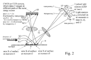
- Figure 2 shows a scheme of one solution of the invention, in which the area X of the surface is imaged three times in different parts of the same image sensor, during a single camera exposure.
- the transparencies 30, 31, and 32 are used to project an illumination pattern of a specific type, from the light sources 15 - 17, onto the desired location on the moving surface 18 being imaged, through the optics 12.
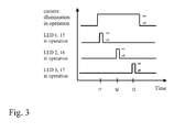
- Figure 3 shows the operation of the camera in connection with the light sources (LED1 - 3) 15, 16, and 17.
- the exposure of the camera is continuous during the measurement, but the light sources 15, 16, and 17 are switched on at different times t1, t2, and t3.
- the total exposure time of the camera is thus greater than the time t1 - t3.
- the exposure starts before the moment in time t1 and ends after the moment in time t3.
- three differently illuminated images A, B, and C are taken consecutively of the moving subject X, in such a way that, due to the movement, these temporally consecutively taken images are imaged through the imaging optics 11 in different areas of the camera's image sensor 10.
- images D, E, and F are further taken of the area Y near to the subject X, in such a way that they have the same illumination, typically without any patterned mask.
- the corresponding pixels of area Y in each image are determined, for example, using image correlation.
- the term corresponding pixel refers to the image pixel corresponding to the same location in different images.
- Image Y can be used to seek corresponding pixels, because the images D, E, and F taken of it are taken using the same illumination, so that the features of the surface appear the same in each image.
- Corresponding pixels are not necessarily found with the same accuracy in the images A, B, and C, because in each image a different sine-pattern illumination is implemented with the aid of transparencies, and covers the features of the surface differently in each image.
- an image, illuminated in three different ways, of the moving subject X is obtained with the aid of the image area Y.
- the three exposure moments can be synchronized in such a way that the sine patterns of the three different images are on the surface X in a specific desired phase shift.
- the topography of the surface can be calculated with the aid of these three images.
- Figure 7 shows the calculation formula when the phase shift of the images is precisely 120 degrees and 240 degrees between the different images. The topography can then also be calculated when the phase shift of the sine patterns is other than 120 and 240 degrees.
- the mutual value of the phase shifts can also be determined computationally, when the corresponding pixels of the surface in the different images are known and when the illumination patterns are assumed to consist of same-phase sine patterns.
- Methods for this mathematical problem have been developed, for instance, Z. Wang: Advanced iterative algorithm for phase extraction of randomly phase-shifted interferograms, Optics letters, July 15, 2004, Vol. 29, No. 14 .
- the topographic map can then be defined computationally with the aid of the mean phase-shift angles determined using the aforementioned method.
- the height difference of the area of the surface corresponding to the individual image pixels relative to the surrounding area then appears as a change in the phase of the sine pattern relative to the phase of the sine pattern of the environment.
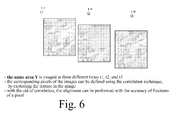
- Figure 6 shows a situation according to the invention, in which Y is imaged three times at the moments t1, t2, and t3 in different areas of the camera cell.
- the precise location of the surface Y between the different images, i.e. the corresponding pixels, is determined, for example, using the correlation technique.
- the corresponding pixels can be defined with good accuracy, because in the images taken at different times there is essentially the same type of illumination and the features of the surface appear in the same ways in the different images.
- Figures 7a and 7b shows a method of calculating the topography (Z co-ordinate), according to the invention, when there are phase shifts, between the three sine patterns, of 120 degrees and 240 degrees relative to the surface X.
- the surface is illuminated at different times, by means of three different types of sine-shape illumination patterns.
- the phases of the sine patterns relative to each other are 0, 2 ⁇ /3, and 4 ⁇ /3.
- the camera measures 3 signals a, b, and c at different moments in time, for each image point, i.e. pixel of the surface.
- Figure 8 shows one alternative manner, according to the invention, to implement the measurement principle shown in Figure 1 , in which the beams of the light sources LED 1 - 3 are separated from each other.
- the three separate transparencies are replaced with a single transparency, of which only one third is illuminated at a time, with the aid of the LEDs LED1, LED2, and LED3.
- the LEDs can, in principle, also be replaced with laser sources, xenon-light sources, or some other light sources that can be controlled in a pulsed manner.
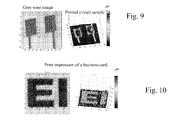
- Figure 9 shows the first laboratory test results of the invention.
- a) is a 2D image (sum of the sine patterns) calculated from three sine patterns
- figure b) is a 3D map calculated with the aid of phase shift.
- the pixel size is about 7 ⁇ m and the area of the image is about 4 mm x 4 mm.
- the height of the conductor image calculated from the phase of the sine pattern is in the order of 10 ⁇ m.
- Figure 10 shows other test results of the invention, in which a topography map was measured in a laboratory from the surface of a business card.
- the size of the image is about 4 mm x 4 mm and the height of the print impression about 10 ⁇ m.
- Two light sources 19 and 20 are placed on different sides of the surface 18 being imaged and are used to illuminate, at the moments in time T 1 and T2, the same area X of the surface, which is imaged using imaging optics, at the moments in time T1 and T2, in different parts of the image sensor.
- a third light source 21 illuminates the area Y at the same angle of illumination, at both moments in time T1 and T2. This allows the same area X to be imaged twice in different types of illumination, in such a way that the corresponding pixels of the images can be defined in the same way, with the aid of the illuminated area Y.
- a topographic map of the surface can be defined using the images taken from two opposite directions, with the aid of the photometric stereo method.
- the advantages of the method are its simple construction and the independence of the measurement from the colour of the surface, because the illumination from two directions can be made using light of the same colour.
- Figure 12 shows an alternative solution, in which six light sources, and correspondingly six transparencies 1 are used.
- an image according to Figure 13 is created for the cell 11.
- the area X and the reference area Y next to it can be imaged six times at different moments in time, in such a way that in three images the area X is illuminated using different types of sine-form illumination patterns, and in three images the same area X is illuminated using coloured light, without sine-pattern masks.
- the reference area Y is illuminated at six different moments in time in the same way with the same colour of light.
- the same arrangement can be used to measure not only the topography of the surface, but also the colour of the surface.
- the area X is illuminated from the same direction, but with different colours.
- the area Y is illuminated at all six different moments in time using the same illumination geometry and the same colour of light, so that it can be used to calculate the corresponding pixels.
- the method it is possible to take two or three images, or even some other number of images.
- the images, illuminated in different ways, of the same subject 8 can be used, not only for measuring topography and colour, but also for other spectroscopic measurement as well as for measurement of glossiness and scattering and polarization properties of a surface, for instance.
- the images taken at different times of the area X are illuminated in different ways using polarized light.
- the images taken at different times of the area X are illuminated using light of the same colour and polarized in the same way, but from different directions.
- the reference area Y, illuminated in the same way is used to synchronize these images illuminated in different ways.
- the image-formation area 10 is typically a cell of one camera, but within the scope of the invention, the imaging area can also be formed of the cells of two or more cameras.
Landscapes
- Physics & Mathematics (AREA)
- General Physics & Mathematics (AREA)
- Engineering & Computer Science (AREA)
- Biochemistry (AREA)
- Health & Medical Sciences (AREA)
- Life Sciences & Earth Sciences (AREA)
- Chemical & Material Sciences (AREA)
- Analytical Chemistry (AREA)
- General Health & Medical Sciences (AREA)
- Immunology (AREA)
- Pathology (AREA)
- Computer Vision & Pattern Recognition (AREA)
- Textile Engineering (AREA)
- Quality & Reliability (AREA)
- Length Measuring Devices By Optical Means (AREA)
- Investigating Or Analysing Materials By Optical Means (AREA)
Applications Claiming Priority (1)
| Application Number | Priority Date | Filing Date | Title |
|---|---|---|---|
| FI20075829A FI121151B (fi) | 2007-11-22 | 2007-11-22 | Menetelmä ja laitteisto liikkuvan pinnan topografian ja optisten ominaisuuksien määrittämiseksi |
Publications (3)
| Publication Number | Publication Date |
|---|---|
| EP2065675A2 true EP2065675A2 (de) | 2009-06-03 |
| EP2065675A3 EP2065675A3 (de) | 2010-08-25 |
| EP2065675B1 EP2065675B1 (de) | 2012-05-16 |
Family
ID=38786758
Family Applications (1)
| Application Number | Title | Priority Date | Filing Date |
|---|---|---|---|
| EP08169222A Not-in-force EP2065675B1 (de) | 2007-11-22 | 2008-11-17 | Verfahren und Vorrichtung zum Bestimmen der Topografie und optischen Eigenschaften einer bewegenden Oberfläche |
Country Status (4)
| Country | Link |
|---|---|
| US (1) | US8363903B2 (de) |
| EP (1) | EP2065675B1 (de) |
| ES (1) | ES2388314T3 (de) |
| FI (1) | FI121151B (de) |
Families Citing this family (8)
| Publication number | Priority date | Publication date | Assignee | Title |
|---|---|---|---|---|
| FI20075975A7 (fi) * | 2007-12-31 | 2009-07-01 | Metso Automation Oy | Rainan mittaus |
| EP2500687A3 (de) * | 2011-03-14 | 2013-02-20 | Heliotis SA | Strukturierter Lichtprojektor |
| DE102012104282A1 (de) * | 2012-05-16 | 2013-11-21 | Isra Vision Ag | Verfahren und Vorrichtung zur Inspektion von Oberflächen eines untersuchten Objekts |
| US9581554B2 (en) * | 2013-05-30 | 2017-02-28 | Seagate Technology Llc | Photon emitter array |
| JP6857079B2 (ja) * | 2017-05-09 | 2021-04-14 | 株式会社キーエンス | 画像検査装置 |
| WO2019058750A1 (ja) * | 2017-09-20 | 2019-03-28 | 倉敷紡績株式会社 | 撮像システム、撮像方法および撮像素子 |
| KR101955847B1 (ko) * | 2018-01-23 | 2019-03-11 | 한국표준과학연구원 | 위상천이 편향측정법에서 비선형 응답특성을 보상하기 위한 시스템 및 방법 |
| DE102022002963B4 (de) * | 2022-08-16 | 2024-08-22 | Baumer lnspection GmbH | Optische Prüfvorrichtung und Prüfverfahren |
Citations (1)
| Publication number | Priority date | Publication date | Assignee | Title |
|---|---|---|---|---|
| EP0898163A1 (de) | 1997-08-22 | 1999-02-24 | Fraunhofer-Gesellschaft Zur Förderung Der Angewandten Forschung E.V. | Verfahren und Vorrichtung zur automatischen Prüfung bewegter Oberflächen |
Family Cites Families (10)
| Publication number | Priority date | Publication date | Assignee | Title |
|---|---|---|---|---|
| US4634279A (en) * | 1984-02-06 | 1987-01-06 | Robotic Vision Systems, Inc. | Method of three-dimensional measurement with few projected patterns |
| JP3914638B2 (ja) * | 1997-09-09 | 2007-05-16 | シーケーディ株式会社 | 形状計測装置 |
| FI20000032A7 (fi) * | 2000-01-07 | 2001-10-26 | Spectra Physics Visiontech Oy | Järjestely ja menetelmä pinnan tarkistamiseksi |
| US6496270B1 (en) * | 2000-02-17 | 2002-12-17 | Gsi Lumonics, Inc. | Method and system for automatically generating reference height data for use in a three-dimensional inspection system |
| US6501554B1 (en) * | 2000-06-20 | 2002-12-31 | Ppt Vision, Inc. | 3D scanner and method for measuring heights and angles of manufactured parts |
| FI20001568L (fi) * | 2000-06-30 | 2001-12-31 | Thermo Radiometrie Oy | Pinnan muotojen määrittäminen |
| DE10063293A1 (de) * | 2000-12-19 | 2002-07-04 | Fraunhofer Ges Forschung | Verfahren und Vorrichtung zur mehrkanaligen Inspektion von Oberflächen im Durchlauf |
| US7440590B1 (en) * | 2002-05-21 | 2008-10-21 | University Of Kentucky Research Foundation | System and technique for retrieving depth information about a surface by projecting a composite image of modulated light patterns |
| US20050219553A1 (en) * | 2003-07-31 | 2005-10-06 | Kelly Patrick V | Monitoring apparatus |
| US7400414B2 (en) * | 2005-10-31 | 2008-07-15 | Mitutoyo Corporation | Hand-size structured-light three-dimensional metrology imaging system and method |
-
2007
- 2007-11-22 FI FI20075829A patent/FI121151B/fi not_active IP Right Cessation
-
2008
- 2008-11-17 EP EP08169222A patent/EP2065675B1/de not_active Not-in-force
- 2008-11-17 ES ES08169222T patent/ES2388314T3/es active Active
- 2008-11-21 US US12/276,215 patent/US8363903B2/en not_active Expired - Fee Related
Patent Citations (1)
| Publication number | Priority date | Publication date | Assignee | Title |
|---|---|---|---|---|
| EP0898163A1 (de) | 1997-08-22 | 1999-02-24 | Fraunhofer-Gesellschaft Zur Förderung Der Angewandten Forschung E.V. | Verfahren und Vorrichtung zur automatischen Prüfung bewegter Oberflächen |
Non-Patent Citations (1)
| Title |
|---|
| Z. WANG: "Advanced iterative algorithm for phase extraction of randomly phase-shifted interferograms", OPTICS LETTERS, vol. 29, no. 14, 15 July 2004 (2004-07-15) |
Also Published As
| Publication number | Publication date |
|---|---|
| FI121151B (fi) | 2010-07-30 |
| EP2065675A3 (de) | 2010-08-25 |
| EP2065675B1 (de) | 2012-05-16 |
| ES2388314T3 (es) | 2012-10-11 |
| FI20075829A0 (fi) | 2007-11-22 |
| FI20075829L (fi) | 2009-05-23 |
| US8363903B2 (en) | 2013-01-29 |
| ES2388314T8 (es) | 2012-10-25 |
| US20090135434A1 (en) | 2009-05-28 |
Similar Documents
| Publication | Publication Date | Title |
|---|---|---|
| EP2065675B1 (de) | Verfahren und Vorrichtung zum Bestimmen der Topografie und optischen Eigenschaften einer bewegenden Oberfläche | |
| CN100491909C (zh) | 三维测定装置 | |
| JP3519698B2 (ja) | 3次元形状測定方法 | |
| US7027639B2 (en) | High speed optical image acquisition system with extended dynamic range | |
| US9958251B1 (en) | Single snap-shot fringe projection system | |
| WO2008126647A1 (ja) | 形状測定装置及び形状測定方法 | |
| WO2014126778A2 (en) | Surface topography interferometer with surface color | |
| CN109387155A (zh) | 形貌检测装置与形貌检测方法 | |
| EP1114993A2 (de) | Verfahren und Vorrichtung zur Untersuchung von Oberflächen | |
| JP2016161513A (ja) | 計測装置および計測方法 | |
| KR100785802B1 (ko) | 입체 형상 측정장치 | |
| CN107655421A (zh) | 采用立体扫描相机对表面进行扫描的工艺和装置 | |
| CN102331240B (zh) | 检查装置以及检查方法 | |
| US20080117438A1 (en) | System and method for object inspection using relief determination | |
| CN107329373B (zh) | 一种套刻误差测量装置及方法 | |
| JP2000121323A (ja) | 表面高さ検査方法及びその検査装置並びにカラーフィルタ基板、その検査方法及びその製造方法 | |
| KR20080090225A (ko) | 편광분리 간섭계를 이용한 표면형상 측정장치 및 방법. | |
| CN206223105U (zh) | 基于数字散斑干涉的变形及斜率同步测量装置 | |
| JP2003042734A (ja) | 表面形状測定方法及び表面形状測定装置 | |
| JP2010243496A (ja) | 物体の少なくとも部分的に反射する表面を光学的に検査するための方法および装置 | |
| US20140085424A1 (en) | Scanner | |
| JP2007327896A (ja) | 検査装置 | |
| JP3921432B2 (ja) | モアレ光学系を用いた形状測定装置及び形状測定方法 | |
| JP4402849B2 (ja) | 表面形状測定方法及び表面形状測定装置 | |
| JPH0587541A (ja) | 2次元情報測定装置 |
Legal Events
| Date | Code | Title | Description |
|---|---|---|---|
| PUAI | Public reference made under article 153(3) epc to a published international application that has entered the european phase |
Free format text: ORIGINAL CODE: 0009012 |
|
| AK | Designated contracting states |
Kind code of ref document: A2 Designated state(s): AT BE BG CH CY CZ DE DK EE ES FI FR GB GR HR HU IE IS IT LI LT LU LV MC MT NL NO PL PT RO SE SI SK TR |
|
| AX | Request for extension of the european patent |
Extension state: AL BA MK RS |
|
| PUAL | Search report despatched |
Free format text: ORIGINAL CODE: 0009013 |
|
| AK | Designated contracting states |
Kind code of ref document: A3 Designated state(s): AT BE BG CH CY CZ DE DK EE ES FI FR GB GR HR HU IE IS IT LI LT LU LV MC MT NL NO PL PT RO SE SI SK TR |
|
| AX | Request for extension of the european patent |
Extension state: AL BA MK RS |
|
| RIC1 | Information provided on ipc code assigned before grant |
Ipc: G01N 21/89 20060101ALI20100721BHEP Ipc: G01B 11/25 20060101AFI20090427BHEP |
|
| AKX | Designation fees paid |
Designated state(s): AT BE BG CH CY CZ DE DK EE ES FI FR GB GR HR HU IE IS IT LI LT LU LV MC MT NL NO PL PT RO SE SI SK TR |
|
| 17P | Request for examination filed |
Effective date: 20081117 |
|
| GRAP | Despatch of communication of intention to grant a patent |
Free format text: ORIGINAL CODE: EPIDOSNIGR1 |
|
| RIC1 | Information provided on ipc code assigned before grant |
Ipc: G01N 21/47 20060101ALI20110714BHEP Ipc: B41F 33/00 20060101ALI20110714BHEP Ipc: G01B 11/25 20060101AFI20110714BHEP Ipc: G01N 21/89 20060101ALI20110714BHEP |
|
| GRAS | Grant fee paid |
Free format text: ORIGINAL CODE: EPIDOSNIGR3 |
|
| GRAA | (expected) grant |
Free format text: ORIGINAL CODE: 0009210 |
|
| RAP1 | Party data changed (applicant data changed or rights of an application transferred) |
Owner name: TEKNOLOGIAN TUTKIMUSKESKUS VTT |
|
| AK | Designated contracting states |
Kind code of ref document: B1 Designated state(s): AT BE BG CH CY CZ DE DK EE ES FI FR GB GR HR HU IE IS IT LI LT LU LV MC MT NL NO PL PT RO SE SI SK TR |
|
| REG | Reference to a national code |
Ref country code: GB Ref legal event code: FG4D |
|
| REG | Reference to a national code |
Ref country code: CH Ref legal event code: EP |
|
| REG | Reference to a national code |
Ref country code: AT Ref legal event code: REF Ref document number: 558297 Country of ref document: AT Kind code of ref document: T Effective date: 20120615 |
|
| REG | Reference to a national code |
Ref country code: IE Ref legal event code: FG4D |
|
| REG | Reference to a national code |
Ref country code: DE Ref legal event code: R096 Ref document number: 602008015562 Country of ref document: DE Effective date: 20120719 |
|
| REG | Reference to a national code |
Ref country code: NL Ref legal event code: VDEP Effective date: 20120516 |
|
| REG | Reference to a national code |
Ref country code: ES Ref legal event code: FG2A Ref document number: 2388314 Country of ref document: ES Kind code of ref document: T3 Effective date: 20121011 |
|
| REG | Reference to a national code |
Ref country code: LT Ref legal event code: MG4D Effective date: 20120516 |
|
| PG25 | Lapsed in a contracting state [announced via postgrant information from national office to epo] |
Ref country code: FI Free format text: LAPSE BECAUSE OF FAILURE TO SUBMIT A TRANSLATION OF THE DESCRIPTION OR TO PAY THE FEE WITHIN THE PRESCRIBED TIME-LIMIT Effective date: 20120516 Ref country code: PL Free format text: LAPSE BECAUSE OF FAILURE TO SUBMIT A TRANSLATION OF THE DESCRIPTION OR TO PAY THE FEE WITHIN THE PRESCRIBED TIME-LIMIT Effective date: 20120516 Ref country code: CY Free format text: LAPSE BECAUSE OF FAILURE TO SUBMIT A TRANSLATION OF THE DESCRIPTION OR TO PAY THE FEE WITHIN THE PRESCRIBED TIME-LIMIT Effective date: 20120516 Ref country code: IS Free format text: LAPSE BECAUSE OF FAILURE TO SUBMIT A TRANSLATION OF THE DESCRIPTION OR TO PAY THE FEE WITHIN THE PRESCRIBED TIME-LIMIT Effective date: 20120916 Ref country code: NO Free format text: LAPSE BECAUSE OF FAILURE TO SUBMIT A TRANSLATION OF THE DESCRIPTION OR TO PAY THE FEE WITHIN THE PRESCRIBED TIME-LIMIT Effective date: 20120816 Ref country code: LT Free format text: LAPSE BECAUSE OF FAILURE TO SUBMIT A TRANSLATION OF THE DESCRIPTION OR TO PAY THE FEE WITHIN THE PRESCRIBED TIME-LIMIT Effective date: 20120516 Ref country code: SE Free format text: LAPSE BECAUSE OF FAILURE TO SUBMIT A TRANSLATION OF THE DESCRIPTION OR TO PAY THE FEE WITHIN THE PRESCRIBED TIME-LIMIT Effective date: 20120516 |
|
| REG | Reference to a national code |
Ref country code: AT Ref legal event code: MK05 Ref document number: 558297 Country of ref document: AT Kind code of ref document: T Effective date: 20120516 |
|
| PG25 | Lapsed in a contracting state [announced via postgrant information from national office to epo] |
Ref country code: LV Free format text: LAPSE BECAUSE OF FAILURE TO SUBMIT A TRANSLATION OF THE DESCRIPTION OR TO PAY THE FEE WITHIN THE PRESCRIBED TIME-LIMIT Effective date: 20120516 Ref country code: HR Free format text: LAPSE BECAUSE OF FAILURE TO SUBMIT A TRANSLATION OF THE DESCRIPTION OR TO PAY THE FEE WITHIN THE PRESCRIBED TIME-LIMIT Effective date: 20120516 Ref country code: GR Free format text: LAPSE BECAUSE OF FAILURE TO SUBMIT A TRANSLATION OF THE DESCRIPTION OR TO PAY THE FEE WITHIN THE PRESCRIBED TIME-LIMIT Effective date: 20120817 Ref country code: PT Free format text: LAPSE BECAUSE OF FAILURE TO SUBMIT A TRANSLATION OF THE DESCRIPTION OR TO PAY THE FEE WITHIN THE PRESCRIBED TIME-LIMIT Effective date: 20120917 Ref country code: SI Free format text: LAPSE BECAUSE OF FAILURE TO SUBMIT A TRANSLATION OF THE DESCRIPTION OR TO PAY THE FEE WITHIN THE PRESCRIBED TIME-LIMIT Effective date: 20120516 |
|
| PG25 | Lapsed in a contracting state [announced via postgrant information from national office to epo] |
Ref country code: BE Free format text: LAPSE BECAUSE OF FAILURE TO SUBMIT A TRANSLATION OF THE DESCRIPTION OR TO PAY THE FEE WITHIN THE PRESCRIBED TIME-LIMIT Effective date: 20120516 |
|
| PG25 | Lapsed in a contracting state [announced via postgrant information from national office to epo] |
Ref country code: DK Free format text: LAPSE BECAUSE OF FAILURE TO SUBMIT A TRANSLATION OF THE DESCRIPTION OR TO PAY THE FEE WITHIN THE PRESCRIBED TIME-LIMIT Effective date: 20120516 Ref country code: NL Free format text: LAPSE BECAUSE OF FAILURE TO SUBMIT A TRANSLATION OF THE DESCRIPTION OR TO PAY THE FEE WITHIN THE PRESCRIBED TIME-LIMIT Effective date: 20120516 Ref country code: EE Free format text: LAPSE BECAUSE OF FAILURE TO SUBMIT A TRANSLATION OF THE DESCRIPTION OR TO PAY THE FEE WITHIN THE PRESCRIBED TIME-LIMIT Effective date: 20120516 Ref country code: CZ Free format text: LAPSE BECAUSE OF FAILURE TO SUBMIT A TRANSLATION OF THE DESCRIPTION OR TO PAY THE FEE WITHIN THE PRESCRIBED TIME-LIMIT Effective date: 20120516 Ref country code: SK Free format text: LAPSE BECAUSE OF FAILURE TO SUBMIT A TRANSLATION OF THE DESCRIPTION OR TO PAY THE FEE WITHIN THE PRESCRIBED TIME-LIMIT Effective date: 20120516 Ref country code: RO Free format text: LAPSE BECAUSE OF FAILURE TO SUBMIT A TRANSLATION OF THE DESCRIPTION OR TO PAY THE FEE WITHIN THE PRESCRIBED TIME-LIMIT Effective date: 20120516 Ref country code: AT Free format text: LAPSE BECAUSE OF FAILURE TO SUBMIT A TRANSLATION OF THE DESCRIPTION OR TO PAY THE FEE WITHIN THE PRESCRIBED TIME-LIMIT Effective date: 20120516 |
|
| PLBE | No opposition filed within time limit |
Free format text: ORIGINAL CODE: 0009261 |
|
| STAA | Information on the status of an ep patent application or granted ep patent |
Free format text: STATUS: NO OPPOSITION FILED WITHIN TIME LIMIT |
|
| 26N | No opposition filed |
Effective date: 20130219 |
|
| REG | Reference to a national code |
Ref country code: DE Ref legal event code: R097 Ref document number: 602008015562 Country of ref document: DE Effective date: 20130219 |
|
| REG | Reference to a national code |
Ref country code: CH Ref legal event code: PL |
|
| PG25 | Lapsed in a contracting state [announced via postgrant information from national office to epo] |
Ref country code: LI Free format text: LAPSE BECAUSE OF NON-PAYMENT OF DUE FEES Effective date: 20121130 Ref country code: CH Free format text: LAPSE BECAUSE OF NON-PAYMENT OF DUE FEES Effective date: 20121130 Ref country code: BG Free format text: LAPSE BECAUSE OF FAILURE TO SUBMIT A TRANSLATION OF THE DESCRIPTION OR TO PAY THE FEE WITHIN THE PRESCRIBED TIME-LIMIT Effective date: 20120816 |
|
| REG | Reference to a national code |
Ref country code: IE Ref legal event code: MM4A |
|
| PG25 | Lapsed in a contracting state [announced via postgrant information from national office to epo] |
Ref country code: IE Free format text: LAPSE BECAUSE OF NON-PAYMENT OF DUE FEES Effective date: 20121117 |
|
| PG25 | Lapsed in a contracting state [announced via postgrant information from national office to epo] |
Ref country code: MT Free format text: LAPSE BECAUSE OF FAILURE TO SUBMIT A TRANSLATION OF THE DESCRIPTION OR TO PAY THE FEE WITHIN THE PRESCRIBED TIME-LIMIT Effective date: 20120516 |
|
| PG25 | Lapsed in a contracting state [announced via postgrant information from national office to epo] |
Ref country code: MC Free format text: LAPSE BECAUSE OF NON-PAYMENT OF DUE FEES Effective date: 20121130 Ref country code: TR Free format text: LAPSE BECAUSE OF FAILURE TO SUBMIT A TRANSLATION OF THE DESCRIPTION OR TO PAY THE FEE WITHIN THE PRESCRIBED TIME-LIMIT Effective date: 20120516 |
|
| PG25 | Lapsed in a contracting state [announced via postgrant information from national office to epo] |
Ref country code: LU Free format text: LAPSE BECAUSE OF NON-PAYMENT OF DUE FEES Effective date: 20121117 |
|
| PG25 | Lapsed in a contracting state [announced via postgrant information from national office to epo] |
Ref country code: HU Free format text: LAPSE BECAUSE OF FAILURE TO SUBMIT A TRANSLATION OF THE DESCRIPTION OR TO PAY THE FEE WITHIN THE PRESCRIBED TIME-LIMIT Effective date: 20081117 |
|
| PGFP | Annual fee paid to national office [announced via postgrant information from national office to epo] |
Ref country code: GB Payment date: 20141219 Year of fee payment: 7 Ref country code: ES Payment date: 20141226 Year of fee payment: 7 |
|
| PGFP | Annual fee paid to national office [announced via postgrant information from national office to epo] |
Ref country code: FR Payment date: 20141219 Year of fee payment: 7 |
|
| PGFP | Annual fee paid to national office [announced via postgrant information from national office to epo] |
Ref country code: DE Payment date: 20141222 Year of fee payment: 7 Ref country code: IT Payment date: 20141223 Year of fee payment: 7 |
|
| REG | Reference to a national code |
Ref country code: DE Ref legal event code: R119 Ref document number: 602008015562 Country of ref document: DE |
|
| GBPC | Gb: european patent ceased through non-payment of renewal fee |
Effective date: 20151117 |
|
| PG25 | Lapsed in a contracting state [announced via postgrant information from national office to epo] |
Ref country code: IT Free format text: LAPSE BECAUSE OF NON-PAYMENT OF DUE FEES Effective date: 20151117 |
|
| REG | Reference to a national code |
Ref country code: FR Ref legal event code: ST Effective date: 20160729 |
|
| PG25 | Lapsed in a contracting state [announced via postgrant information from national office to epo] |
Ref country code: DE Free format text: LAPSE BECAUSE OF NON-PAYMENT OF DUE FEES Effective date: 20160601 Ref country code: GB Free format text: LAPSE BECAUSE OF NON-PAYMENT OF DUE FEES Effective date: 20151117 |
|
| PG25 | Lapsed in a contracting state [announced via postgrant information from national office to epo] |
Ref country code: FR Free format text: LAPSE BECAUSE OF NON-PAYMENT OF DUE FEES Effective date: 20151130 |
|
| REG | Reference to a national code |
Ref country code: ES Ref legal event code: FD2A Effective date: 20161227 |
|
| PG25 | Lapsed in a contracting state [announced via postgrant information from national office to epo] |
Ref country code: ES Free format text: LAPSE BECAUSE OF NON-PAYMENT OF DUE FEES Effective date: 20151118 |