EP2065717B1 - Tragbare Diagnosevorrichtung für Fahrzeuge - Google Patents
Tragbare Diagnosevorrichtung für Fahrzeuge Download PDFInfo
- Publication number
- EP2065717B1 EP2065717B1 EP20080161437 EP08161437A EP2065717B1 EP 2065717 B1 EP2065717 B1 EP 2065717B1 EP 20080161437 EP20080161437 EP 20080161437 EP 08161437 A EP08161437 A EP 08161437A EP 2065717 B1 EP2065717 B1 EP 2065717B1
- Authority
- EP
- European Patent Office
- Prior art keywords
- firmware
- diagnosis device
- updating
- hand
- held
- Prior art date
- Legal status (The legal status is an assumption and is not a legal conclusion. Google has not performed a legal analysis and makes no representation as to the accuracy of the status listed.)
- Not-in-force
Links
Images



Classifications
-
- G—PHYSICS
- G06—COMPUTING OR CALCULATING; COUNTING
- G06F—ELECTRIC DIGITAL DATA PROCESSING
- G06F11/00—Error detection; Error correction; Monitoring
- G06F11/22—Detection or location of defective computer hardware by testing during standby operation or during idle time, e.g. start-up testing
- G06F11/26—Functional testing
- G06F11/273—Tester hardware, i.e. output processing circuits
-
- G—PHYSICS
- G07—CHECKING-DEVICES
- G07C—TIME OR ATTENDANCE REGISTERS; REGISTERING OR INDICATING THE WORKING OF MACHINES; GENERATING RANDOM NUMBERS; VOTING OR LOTTERY APPARATUS; ARRANGEMENTS, SYSTEMS OR APPARATUS FOR CHECKING NOT PROVIDED FOR ELSEWHERE
- G07C5/00—Registering or indicating the working of vehicles
- G07C5/08—Registering or indicating performance data other than driving, working, idle, or waiting time, with or without registering driving, working, idle or waiting time
- G07C5/0808—Diagnosing performance data
-
- G—PHYSICS
- G07—CHECKING-DEVICES
- G07C—TIME OR ATTENDANCE REGISTERS; REGISTERING OR INDICATING THE WORKING OF MACHINES; GENERATING RANDOM NUMBERS; VOTING OR LOTTERY APPARATUS; ARRANGEMENTS, SYSTEMS OR APPARATUS FOR CHECKING NOT PROVIDED FOR ELSEWHERE
- G07C2205/00—Indexing scheme relating to group G07C5/00
- G07C2205/02—Indexing scheme relating to group G07C5/00 using a vehicle scan tool
-
- G—PHYSICS
- G07—CHECKING-DEVICES
- G07C—TIME OR ATTENDANCE REGISTERS; REGISTERING OR INDICATING THE WORKING OF MACHINES; GENERATING RANDOM NUMBERS; VOTING OR LOTTERY APPARATUS; ARRANGEMENTS, SYSTEMS OR APPARATUS FOR CHECKING NOT PROVIDED FOR ELSEWHERE
- G07C5/00—Registering or indicating the working of vehicles
- G07C5/008—Registering or indicating the working of vehicles communicating information to a remotely located station
Definitions
- the present invention relates to a diagnosis device, especially to a hand-held diagnosis device for vehicles such as automobiles, motorcycles and the like.
- a diagnosis device for vehicles is used for detecting states and malfunctions of a vehicle without dismantling a body of the vehicle and inspecting inner parts of the vehicle.
- Diagnosis devices used on vehicles having jet engines may be implemented as a hardware-type diagnosis device, a software-type diagnosis device or a personal digital assistant (PDA) with a diagnosing function.
- PDA personal digital assistant
- Fig. 5 shows a conventional hardware-type diagnosis device (3) manufactured by Hyundai Motor.
- This diagnosis device (3) only fit for vehicles of designated brands and is hard to update software of the diagnosis device (3). If need to diagnose vehicles of other brands, the owner is forced to buy another diagnosis device. Besides, diagnosis data are only displayed temporarily and unable to be stored.
- a software-type diagnosis device has to combine with a computer to execute its diagnosing function.
- the diagnosis device When diagnosing a vehicle, the diagnosis device must use a serial port of the computer to communicate with the vehicle. Therefore diagnosing vehicles is inconvenient since the ponderous computer is not portable.
- a personal digital assistant (PDA) with a diagnosing function is a power-hungry device and easily causes power failure when diagnosing vehicles.
- the present invention provides a hand-held diagnosis device to mitigate or obviate the aforementioned problems.
- the main objective of the present invention is to provide a hand-held diagnosis device that is easy to carry and operate, connects to a personal computer to update firmware to fit for vehicles of different brands or makers and directly uses the electric power of the vehicle.
- the present invention provides a hand-held diagnosis device according to claim 1.
- the dependent claims relate to advantageous embodiments.
- a hand-held diagnosis device (1) for vehicles in accordance with the present invention is adapted to connect to a personal computer (2).
- the diagnosis device (1) comprises a body (10), a circuit module (11), a display unit (12), a communication port (13), a cable (14) and a button set (15).
- the body (10) is palm-sized and may be a casing, a box or the like.
- the circuit module (11) is mounted in the body (10).
- the display unit (12) is mounted on the body (10) and connected to the circuit module (11) to display data sent from the circuit module (11) and may be implemented as a liquid crystal display module.
- the communication port (13) is mounted on the body (10) and connected to the circuit module (11) and may be implemented as a RS232 serial port.
- the cable (14) is connected to the circuit module (11).
- the button set (15) is mounted on the body (10) and comprises multiple press buttons (15a, 15b, 15c) being connected to the circuit module (11).
- the circuit module (11) may comprise an optional power supply unit (110), a micro-controller unit (MCU) (111), a diagnosing unit (112), a signal converter (113), an optional initializing unit (114), an optional alarm unit (115) and an optional function-selecting unit (116).
- the power supply unit (110) provides power to all electronic elements of the hand-held diagnosis device (1) and may have a voltage-stabilizer (110a) for providing a stable voltage.
- the micro-controller unit (111) is connected to the power supply unit (110) and has a boot sector and a program sector.
- the boot sector has an MCU-firmware update program.
- the MCU-firmware update program corresponds to a computer software providing a firmware-updating program to be executed for updating firmware of the micro-controller unit (111).
- the computer software is installed on the personal computer (2) and the firmware-updating program provides a firmware-updating function.
- a control authority of the micro-controller unit (111) is controlled by the MCU-firmware update program of the boot sector and the computer software embeds an updating code in the boot sector.
- the diagnosing unit (112) is connected to the micro-controller unit (111) and the cable (14) and has a communication signal-processing chip (112a).
- the communication signal-processing chip (112a) may be implemented as a communication signal-processing chip with two inputs and one output that corresponds with international standards and can be widely used.
- the diagnosing unit (112) diagnoses states of the vehicle via the cable (14).
- the cable (14) is also a transfer medium that transfers electric power of a battery of the vehicle to electronic elements of the hand-held diagnosis device (1).
- the signal converter (113) is connected to the micro-controller unit (111) and the communication port (13) and may be a HIN232 integrated circuit.
- the communication port (13) of the hand-held diagnosis device (1) connects to a communication port (21) of the personal computer (2) via an RS232 cable
- the signal converter (113) then converts serial data sent from the personal computer (2) into readable format for the micro-controller unit (111).
- the initializing unit (114) is connected to the micro-controller unit (111) and executes an initialization of the micro-controller unit (111) after turning on the hand-held diagnosis device (1).
- the alarm unit (115) is connected to the micro-controller unit (111) and has multiple light-emitting elements.
- the light-emitting elements may be mounted on the body (10) and emit lights to respectively represent different operating information of the hand-held diagnosis device (1).
- the micro-controller unit (111) may drive one light-emitting element for warning of malfunctions of the vehicle, another for power indication of the diagnosis device (1) and still another for indicating connection between the diagnosis device (1) and the vehicle.
- the alarm unit (115) has two light-emitting elements respectively representing a power indication and a malfunction indication.
- the light-emitting element of power indication indicates whether the power of the diagnosis device (1) is turned on and keeps flashing when the diagnosis device (1) is working.
- the light-emitting element of malfunction indication indicates that malfunction of the vehicle has been detected.
- the function-selecting unit (116) comprises multiple switches.
- the switches are connected to the micro-controller unit (111) and may be two select-switches (116a, 116c) and one confirm-switch (116b) being correspondingly activated by the press buttons (15a, 15b, 15c) of the button set (15). Therefore, a user can press each of the press buttons (15a, 15b, 15c) to activate each of the switches (116a, 116b, 116c) and command the micro-controller unit (111).
- the press buttons (15a, 15b, 15c) are then implemented as two select-buttons (15a, 15c) with up and down pointers and one confirm-button (15b) due to the corresponding switches of the function-selecting unit (116).
- the hand-held diagnosis device further comprises a storage interface (16).
- the storage interface (16) is connected to the micro-controller unit (111) and adapted to connect to a memory card for recording diagnosis data of the vehicle and may be implemented as a memory card socket for SD (Secure Data Disk) card, micro SD card and the like.
- SD Secure Data Disk
- the hand-hand diagnosis device (1) of the present invention electrically connects to an electronic control unit of a vehicle via the cable (14) and starts to diagnose the vehicle and generates diagnosis data.
- the display unit (12) then display the diagnosis data.
- a user can press different press buttons (15a, 15b, 15c) to switch a displayed screen on the display unit (12).
- the diagnosis data can be further stored in a SD memory card via the storage interface (16).
- the user first connects the diagnosis device (1) and the personal computer (2) with the communication port (13). Then the user executes the MCU-firmware update program of the micro-controller unit (111) by using the firmware-updating program of the computer software installed on the personal computer (2).
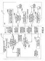
- the firmware-updating process between the micro-controller unit (111) and the personal computer (2) comprises steps of starting firmware-updating function (100), determining whether to execute the firmware-updating function (101), executing the firmware-updating function (102), reading firmware-updating data (103), writing the firmware-updating data (104), determining whether the transmission is finished (105), transmission complete (106), updating complete (107) and rebooting (108).
- the personal computer (2) executes the firmware-updating program of the computer software installed on the personal computer (2) and the firmware-updating program asks the diagnosis device (1) to response whether to start to update firmware.
- the MCU-frmware update program of the diagnosis device (2) determines whether to perform firmware-updating or diagnosing, if determines to update firmware, then responses to the personal computer (2) to start to update firmware, wherein the boot sector in the micro-controller unit (111) receives and confirms signals sent from the personal computer (2) and then returns a confirm signal to the personal computer (2).
- the personal computer (2) communicates with the diagnosis device (1) with a serial communication protocol, starts to transmit firmware-updating data after receiving the confirm signal from the diagnosis device (1) and stops updating firmware when an error occurs.
- the personal computer (2) reads the firmware-updating data datum by datum and transmits the data to the diagnosis device (1) via the communication port (13), wherein each firmware-updating datum from the updating code of the computer software is sent out after communicating with the micro-controller unit (111).
- the diagnosis device (2) stores the firmware-updating data after receiving the firmware-updating data.
- the personal computer (2) determines whether all of the firmware-updating data has been sent to the diagnosis device (1), if not, proceed to step of reading firware-updating data (103) and stop updating firmware when an error occurs, if yes, proceed to the next step (106).
- the personal computer (2) closes the firmware-updating program and sends a message that informs the firmware-updating process has been finished to the diagnosis device (1), the micro-controller unit (111) that gave the control authority to the boot sector then receives the message and confirm firmware-updating is finished.
- the diagnosis device (1) closes the MCU-firmware update program and the micro-controller unit (111) prepares to start an automatic reboot program to reboot the diagnosis device (1) and moves the control authority to the program sector in the micro-controller unit (111).
- the diagnosis device (1) then automatically reboots and displays screen images of diagnosing on the display unit (12), and firmware-updating process is complete.
Landscapes
- Engineering & Computer Science (AREA)
- General Engineering & Computer Science (AREA)
- Physics & Mathematics (AREA)
- General Physics & Mathematics (AREA)
- Theoretical Computer Science (AREA)
- Computer Hardware Design (AREA)
- Quality & Reliability (AREA)
- Stored Programmes (AREA)
Claims (9)
- Tragbare Diagnosevorrichtung (1) für ein Fahrzeug mit elektronischer Steuereinheit (ECU), wobei die tragbare Diagnosevorrichtung (1) einen Körper (10), ein Schaltungsmodul (11), welches im Körper (10) angebracht ist, eine Anzeigeeinheit (12), welche auf dem Körper (10) angebracht ist und mit dem Schaltungsmodul (11) verbunden ist, ein Kabel (13), welches ausgelegt ist, um mit der elektronischen Steuereinheit (ECU) des Fahrzeugs zu verbinden, und welches mit dem Schaltungsmodul (11) verbunden ist, und einen Knöpfesatz (15) umfasst, welcher auf dem Körper (10) angebracht ist und mit dem Schaltungsmodul (11) verbunden ist, wobei die tragbare Diagnosevorrichtung (1) dadurch gekennzeichnet ist, dass:die tragbare Diagnosevorrichtung (1) einen Kommunikationsanschluss (13) aufweist, welcher auf dem Körper (10) angebracht und mit dem Schaltungsmodul (11) verbunden ist;wobei das Schaltungsmodul (11) umfasst:eine Mikrocontrollereinheit (111), welche aufweist:einen Bootsektor mit einem MCU-Firmware-Aktualisierungsprogramm, undeinen Programmsektor;eine diagnostizierende Einheit (112), welche mit der Mikrocontrollereinheit (111) und dem Kabel (14) und den diagnostizierenden Zuständen des Fahrzeugs über das Kabel (14) verbunden ist, wenn das Kabel (14) mit der elektronischen Steuereinheit (ECU) des Fahrzeugs verbunden ist;undeinen Signalwandler (113), welcher mit der Mikrocontroller-Einheit (111) und dem Kommunikationsanschluss (13) verbunden ist und serielle Daten vom Kommunikationsanschluss (13) in ein lesbares Format für die Mikrocontrollereinheit (111) umwandelt;eine Speicherschnittstelle (16), welche mit der Mikrocontrollereinheit (111) verbunden und ausgelegt ist, um eine Verbindung mit einer Speicherkarte herzustellen, die Diagnosedaten des Fahrzeugs aufzeichnet; undder Kommunikationsanschluss (13) ausgelegt ist, um eine Verbindung mit einem Personalcomputer (2) herzustellen, welcher eine Computersoftware aufweist, die ein Firmware-Aktualisierungsprogramm bereitstellt, um dem Personalcomputer (2) zu erlauben, einen Firmware-Aktualisierungsvorgang auf der Mikrocontrollereinheit (111) durchzuführen; undwobei die Diagnosevorrichtung (1) selbst in der Lage ist, die Firmware-Aktualisierungsdaten zu speichern, die sie vom Personalcomputer empfängt, und wobei sie ausgelegt ist, automatisch neu zu starten und Diagnosebildschirmbilder auf der Anzeigeneinheit (12) nach dem Abschließen der Aktualisierung der Firmware anzuzeigen.
- Tragbare Diagnosevorrichtung nach Anspruch 1, wobei das Schaltungsmodul (11) des Weiteren umfasst:eine Stromversorgungseinheit (110), welche Strom für alle elektronischen Elemente der tragbaren Diagnosevorrichtung (1) liefert;eine Initialisierungseinheit (114), welche mit der Mikrocontrollereinheit (111) verbunden ist und eine Initialisierung der Mikrocontrollereinheit (111) nach dem Einschalten der tragbaren Diagnosevorrichtung (1) ausführt;eine Alarmeinheit (115), welche mit der Mikrocontrollereinheit (111) verbunden ist und mehrere Licht abstrahlende Elemente zum jeweiligen Darstellen unterschiedlicher Betriebsinformationen der tragbaren Diagnosevorrichtung (1) aufweist; undeine Funktionsauswahleinheit (116), welche mehrere Schalter aufweist, die mit der Mikrocontrollereinheit (111) verbunden sind, um der Mikrocontrollereinheit (111) zum Betätigen der Schalter zu befehlen.
- Tragbare Diagnosevorrichtung nach Anspruch 1, wobei die Anzeigeeinheit (12) ein Flüssigkristallanzeigemodul ist.
- Tragbare Diagnosevorrichtung nach Anspruch 1, wobei die diagnostizierende Einheit (112) einen Kommunikationssignal-Verarbeitungschip (112a) mit zwei Eingängen und einem Ausgang aufweist.
- Tragbare Diagnosevorrichtung nach Anspruch 1, wobei der Kommunikationsanschluss (13) ein RS232 serieller Anschluss ist.
- Tragbare Diagnosevorrichtung nach Anspruch 5, wobei der Kommunikationsanschluss (13) der Diagnosevorrichtung (112) ausgelegt ist, um elektrisch mit einem Kommunikationsanschluss des Personalcomputers über ein RS232-Kabel verbunden zu sein.
- Tragbare Diagnosevorrichtung nach Anspruch 2, wobei
der Knöpfesatz (15) zwei Auswahlknöpfe (15a, 15c) und einen Bestätigungsknopf (15b) umfasst; und
die Funktionseinheit (116) zwei Auswahlschalter (116a, 116c) und einen Bestätigungsschalter (16b) umfasst, welche entsprechend durch die Auswahlknöpfe (15a, 15c) und den Bestätigungsknopf (15b) des Knöpfesatzes (15) aktiviert werden. - Tragbare Diagnosevorrichtung nach Anspruch 1, wobei die Speicherschnittstelle (16) als ein Speicherkartensockel für SD (Secure Data Disk), Mikro-SD-Karte und Ähnliches umgesetzt ist.
- Verfahren zum Aktualisieren der Firmware einer tragbaren Diagnosevorrichtung nach Anspruch 1, wobei das Verfahren die Schritte umfasst:Verbinden der tragbaren Diagnosevorrichtung (1) mit einem Personalcomputer (2), wobei die tragbare Diagnosevorrichtung (1) ein MCU-Firmware-Aktualisierungsprogramm und der Personalcomputer (2) ein Firmware-Aktualisierungsprogramm besitzt;Starten der Firmware-Aktualisierungsfunktion (100), wobei der Personalcomputer (2) das Firmware-Aktualisierungsprogramm ausführt und das Firmware-Aktualisierungsprogramm die Diagnosevorrichtung (1) anfragt zu reagieren, ob das Aktualisieren der Firmware gestartet werden soll;Bestimmen, ob die Firmware-Aktualisierungsfunktion (101) ausgeführt wird, wobei das MCU-Firmware-Aktualisierungsprogramm der Diagnosevorrichtung (1) bestimmt, ob sie die Firmware-Aktualisierung oder das Diagnostizieren ausführt, wobei sie, wenn sie bestimmt, die Firmware zu aktualisieren, dann dem Personalcomputer (2) antwortet, die Firmware-Aktualisierung zu beginnen;Ausführen der Firmware-Aktualisierungsfunktion (102), wobei der Personalcomputer (2) mit der Diagnosevorrichtung (1) mit einem seriellen Kommunikationsprotokoll über den Kommunikationsanschluss (13) der Diagnosevorrichtung (1) kommuniziert, beginnt Firmware-Aktualisierungsdaten zu übertragen, nachdem er ein Bestätigungssignal von der Diagnosevorrichtung (1) empfangen hat, und die Aktualisierung der Firmware beendet, wenn ein Fehler auftritt;Lesen der Firmeware-Aktualisierungsdaten (103), wobei der Personalcomputer (2) die Firmeware-Aktualisierungsdaten liest und die Daten auf die Diagnosevorrichtung (1) über den Kommunikationsanschluss (13) überträgt;Schreiben der Firmeware-Aktualisierungsdaten (104),wobei die Diagnosevorrichtung (1) die Firmeware-Aktualisierungsdaten nach dem Empfang der Firmeware-Aktualisierungsdaten speichert;Bestimmen, ob die Übertragung beendet ist (105), wobei der Personalcomputer (2) bestimmt, ob alle Firmeware-Aktualisierungsdaten an die Diagnosevorrichtung (1) übertragen worden sind, wenn nicht, dann zum Schritt des Lesens der Firmeware-Aktualisierungsdaten weitergeht und das Aktualisieren der Firmware beendet, wenn ein Fehler auftritt, wenn ja, dann zum nächsten Schritt weitergeht;Abschließen der Übertragung (106), wobei der Personalcomputer (2) das Firmeware-Aktualisierungsprogramm schließt und eine Botschaft an die Diagnosevorrichtung (1) sendet, welche darüber informiert, dass der Firmeware-Aktualisierungsvorgang beendet worden ist;Abschließen der Aktualisierung (107), wobei die Diagnosevorrichtung (1) das MCU-Firmware-Aktualisierungsprogramm schließt; undNeustarten (108), wobei die Diagnosevorrichtung (1) automatisch neu startet und Diagnosebildschirmbilder auf der Anzeigeeinheit (12) nach dem Beenden des Aktualisierens der Firmware anzeigt.
Applications Claiming Priority (1)
| Application Number | Priority Date | Filing Date | Title |
|---|---|---|---|
| TW96145300A TW200922821A (en) | 2007-11-29 | 2007-11-29 | Handheld diagnostic device for vehicle |
Publications (2)
| Publication Number | Publication Date |
|---|---|
| EP2065717A1 EP2065717A1 (de) | 2009-06-03 |
| EP2065717B1 true EP2065717B1 (de) | 2012-12-05 |
Family
ID=40019482
Family Applications (1)
| Application Number | Title | Priority Date | Filing Date |
|---|---|---|---|
| EP20080161437 Not-in-force EP2065717B1 (de) | 2007-11-29 | 2008-07-30 | Tragbare Diagnosevorrichtung für Fahrzeuge |
Country Status (4)
| Country | Link |
|---|---|
| EP (1) | EP2065717B1 (de) |
| JP (1) | JP2009133821A (de) |
| ES (1) | ES2396736T3 (de) |
| TW (1) | TW200922821A (de) |
Cited By (2)
| Publication number | Priority date | Publication date | Assignee | Title |
|---|---|---|---|---|
| CN103685240A (zh) * | 2013-11-25 | 2014-03-26 | 深圳市元征科技股份有限公司 | 基于dpu431的车辆诊断模块及车辆诊断方法 |
| US10977026B2 (en) * | 2018-11-20 | 2021-04-13 | Pegatron Corporation | Data updating system, embedded electronic device and data updating method |
Families Citing this family (5)
| Publication number | Priority date | Publication date | Assignee | Title |
|---|---|---|---|---|
| CN103287400A (zh) * | 2013-02-05 | 2013-09-11 | 深圳市元征科技股份有限公司 | 车辆数据诊断系统及方法 |
| KR20170082770A (ko) | 2016-01-07 | 2017-07-17 | 현대자동차주식회사 | 전자제어장치(electronic control unit, ECU) 리프로그래밍의 경우 보조배터리 심방전 방지 방법 및 장치 |
| TWI607912B (zh) * | 2016-10-14 | 2017-12-11 | 光陽工業股份有限公司 | Program updating method and system of vehicle |
| CN108844746B (zh) * | 2018-05-02 | 2020-09-18 | 赵英英 | 拉索模拟检测总成 |
| EP3961997A1 (de) * | 2020-09-01 | 2022-03-02 | Volvo Truck Corporation | Fahrzeugsteuerungsarchitektur basierend auf einer zentralen koordination von lokal angewandten und aktualisierbaren bewegungsunterstützungsvorrichtungsabstraktionen |
Family Cites Families (14)
| Publication number | Priority date | Publication date | Assignee | Title |
|---|---|---|---|---|
| GB222271A (en) | 1923-08-08 | 1924-10-02 | John Jenkin Jones | An improved key for railway and the like chairs |
| JPH0827220B2 (ja) * | 1988-07-23 | 1996-03-21 | 富士重工業株式会社 | 車輌診断装置 |
| JPH0752143B2 (ja) * | 1989-12-14 | 1995-06-05 | 株式会社ダイフク | データ保管設備 |
| JPH05126685A (ja) * | 1991-10-31 | 1993-05-21 | Nissan Motor Co Ltd | 車両の故障診断装置 |
| US5884202A (en) * | 1995-07-20 | 1999-03-16 | Hewlett-Packard Company | Modular wireless diagnostic test and information system |
| JP3324933B2 (ja) * | 1996-06-05 | 2002-09-17 | 富士重工業株式会社 | 車両用故障診断装置 |
| US5916287A (en) * | 1996-09-30 | 1999-06-29 | Hewlett-Packard Company | Modular automotive diagnostic, test and information system |
| JPH10253505A (ja) * | 1997-03-10 | 1998-09-25 | Honda Motor Co Ltd | 車両診断方法および装置 |
| US6693367B1 (en) * | 2000-04-25 | 2004-02-17 | Snap-On Technologies, Inc. | Single-hand held diagnostic display unit |
| JP2002228551A (ja) * | 2001-01-31 | 2002-08-14 | Haruo Morita | 車両診断システム |
| JP2003131885A (ja) * | 2001-10-24 | 2003-05-09 | Denso Corp | 車載電子制御装置のプログラム書込システム |
| JP2005241599A (ja) * | 2004-02-27 | 2005-09-08 | Fuji Heavy Ind Ltd | データ記録装置およびデータ記録方法 |
| JP4509603B2 (ja) * | 2004-02-27 | 2010-07-21 | 富士重工業株式会社 | 制御ユニットおよびデータ送信方法 |
| JP2006219092A (ja) * | 2005-02-14 | 2006-08-24 | Nissan Motor Co Ltd | 車両故障診断システム、車両故障診断方法、及び車両用故障診断装置 |
-
2007
- 2007-11-29 TW TW96145300A patent/TW200922821A/zh not_active IP Right Cessation
-
2008
- 2008-07-30 EP EP20080161437 patent/EP2065717B1/de not_active Not-in-force
- 2008-07-30 ES ES08161437T patent/ES2396736T3/es active Active
- 2008-08-07 JP JP2008204179A patent/JP2009133821A/ja active Pending
Cited By (2)
| Publication number | Priority date | Publication date | Assignee | Title |
|---|---|---|---|---|
| CN103685240A (zh) * | 2013-11-25 | 2014-03-26 | 深圳市元征科技股份有限公司 | 基于dpu431的车辆诊断模块及车辆诊断方法 |
| US10977026B2 (en) * | 2018-11-20 | 2021-04-13 | Pegatron Corporation | Data updating system, embedded electronic device and data updating method |
Also Published As
| Publication number | Publication date |
|---|---|
| JP2009133821A (ja) | 2009-06-18 |
| EP2065717A1 (de) | 2009-06-03 |
| ES2396736T3 (es) | 2013-02-25 |
| TWI318944B (de) | 2010-01-01 |
| TW200922821A (en) | 2009-06-01 |
Similar Documents
| Publication | Publication Date | Title |
|---|---|---|
| EP2065717B1 (de) | Tragbare Diagnosevorrichtung für Fahrzeuge | |
| CA2815883C (en) | Device and method for managing an electronic control unit of a vehicle | |
| CN202472410U (zh) | 一种基于无线技术的汽车obd故障诊断仪 | |
| KR20170013896A (ko) | 모바일 스마트 단말기를 기반으로 한 개인 자동차 진단 시스템 및 방법 | |
| CN113960991A (zh) | 车辆故障诊断系统、方法、装置、片上系统芯片及车辆 | |
| CN101286067A (zh) | 车载式汽车故障诊断仪 | |
| CN100484784C (zh) | 一种轮胎压力测量系统 | |
| US20080307123A1 (en) | Two-way connectivity USB control device and operation method thereof | |
| KR20150019836A (ko) | 부팅 시 오류 검출 기능을 갖는 멀티미디어 장치 및 그 동작 방법 | |
| US20060238533A1 (en) | Battery power level inspection device co-constructed with system indicators of notebook computer and inspection method thereof | |
| US20240227466A9 (en) | System and method for setting multiple tire sensor identification codes using handheld device | |
| CN1661347B (zh) | 控制单元和数据传输方法 | |
| US11968354B2 (en) | Automatic evaluating apparatus for built-in video recording device of vehicle, system having the same, and method thereof | |
| CN101458524A (zh) | 车辆用的掌上型诊断器 | |
| CN102393734A (zh) | 车用读码卡 | |
| JP2011040026A (ja) | トリガ制御装置およびその方法 | |
| CN201199329Y (zh) | 车载式汽车故障诊断仪 | |
| CN207267456U (zh) | 一种全液晶仪表核心控制板 | |
| US7747909B2 (en) | Debug card | |
| CN118915508A (zh) | 可视化数据交互控制器和电力数字智能系统 | |
| CN110990206A (zh) | 具有主板诊断卡的电子装置及主板诊断方法 | |
| US20100046342A1 (en) | Recording and replaying device | |
| CN102103377B (zh) | 车辆信息学习与诊断方法与系统及运算装置可读存储介质 | |
| TW201313527A (zh) | 一種可自動偵測並驅動連結車輛obd ii通訊協定及主動封包傳遞與無線傳輸之車載編譯整合裝置 | |
| CN207895270U (zh) | 一种离线式惯性测量数据采集装置 |
Legal Events
| Date | Code | Title | Description |
|---|---|---|---|
| PUAI | Public reference made under article 153(3) epc to a published international application that has entered the european phase |
Free format text: ORIGINAL CODE: 0009012 |
|
| AK | Designated contracting states |
Kind code of ref document: A1 Designated state(s): AT BE BG CH CY CZ DE DK EE ES FI FR GB GR HR HU IE IS IT LI LT LU LV MC MT NL NO PL PT RO SE SI SK TR |
|
| AX | Request for extension of the european patent |
Extension state: AL BA MK RS |
|
| 17Q | First examination report despatched |
Effective date: 20090929 |
|
| 17P | Request for examination filed |
Effective date: 20090828 |
|
| AKX | Designation fees paid |
Designated state(s): AT BE BG CH CY CZ DE DK EE ES FI FR GB GR HR HU IE IS IT LI LT LU LV MC MT NL NO PL PT RO SE SI SK TR |
|
| 17Q | First examination report despatched |
Effective date: 20100916 |
|
| REG | Reference to a national code |
Ref country code: DE Ref legal event code: R079 Ref document number: 602008020561 Country of ref document: DE Free format text: PREVIOUS MAIN CLASS: G01R0031000000 Ipc: G06F0011273000 |
|
| RIC1 | Information provided on ipc code assigned before grant |
Ipc: G07C 5/08 20060101ALI20111213BHEP Ipc: B60W 50/00 20060101ALI20111213BHEP Ipc: G06F 11/273 20060101AFI20111213BHEP |
|
| GRAP | Despatch of communication of intention to grant a patent |
Free format text: ORIGINAL CODE: EPIDOSNIGR1 |
|
| GRAS | Grant fee paid |
Free format text: ORIGINAL CODE: EPIDOSNIGR3 |
|
| GRAA | (expected) grant |
Free format text: ORIGINAL CODE: 0009210 |
|
| AK | Designated contracting states |
Kind code of ref document: B1 Designated state(s): AT BE BG CH CY CZ DE DK EE ES FI FR GB GR HR HU IE IS IT LI LT LU LV MC MT NL NO PL PT RO SE SI SK TR |
|
| REG | Reference to a national code |
Ref country code: GB Ref legal event code: FG4D |
|
| REG | Reference to a national code |
Ref country code: CH Ref legal event code: EP |
|
| REG | Reference to a national code |
Ref country code: AT Ref legal event code: REF Ref document number: 587599 Country of ref document: AT Kind code of ref document: T Effective date: 20121215 |
|
| REG | Reference to a national code |
Ref country code: IE Ref legal event code: FG4D |
|
| REG | Reference to a national code |
Ref country code: DE Ref legal event code: R096 Ref document number: 602008020561 Country of ref document: DE Effective date: 20130131 |
|
| REG | Reference to a national code |
Ref country code: ES Ref legal event code: FG2A Ref document number: 2396736 Country of ref document: ES Kind code of ref document: T3 Effective date: 20130225 |
|
| REG | Reference to a national code |
Ref country code: AT Ref legal event code: MK05 Ref document number: 587599 Country of ref document: AT Kind code of ref document: T Effective date: 20121205 |
|
| PG25 | Lapsed in a contracting state [announced via postgrant information from national office to epo] |
Ref country code: SE Free format text: LAPSE BECAUSE OF FAILURE TO SUBMIT A TRANSLATION OF THE DESCRIPTION OR TO PAY THE FEE WITHIN THE PRESCRIBED TIME-LIMIT Effective date: 20121205 Ref country code: NO Free format text: LAPSE BECAUSE OF FAILURE TO SUBMIT A TRANSLATION OF THE DESCRIPTION OR TO PAY THE FEE WITHIN THE PRESCRIBED TIME-LIMIT Effective date: 20130305 Ref country code: FI Free format text: LAPSE BECAUSE OF FAILURE TO SUBMIT A TRANSLATION OF THE DESCRIPTION OR TO PAY THE FEE WITHIN THE PRESCRIBED TIME-LIMIT Effective date: 20121205 Ref country code: LT Free format text: LAPSE BECAUSE OF FAILURE TO SUBMIT A TRANSLATION OF THE DESCRIPTION OR TO PAY THE FEE WITHIN THE PRESCRIBED TIME-LIMIT Effective date: 20121205 Ref country code: HR Free format text: LAPSE BECAUSE OF FAILURE TO SUBMIT A TRANSLATION OF THE DESCRIPTION OR TO PAY THE FEE WITHIN THE PRESCRIBED TIME-LIMIT Effective date: 20121205 |
|
| REG | Reference to a national code |
Ref country code: NL Ref legal event code: VDEP Effective date: 20121205 |
|
| REG | Reference to a national code |
Ref country code: LT Ref legal event code: MG4D |
|
| PG25 | Lapsed in a contracting state [announced via postgrant information from national office to epo] |
Ref country code: PL Free format text: LAPSE BECAUSE OF FAILURE TO SUBMIT A TRANSLATION OF THE DESCRIPTION OR TO PAY THE FEE WITHIN THE PRESCRIBED TIME-LIMIT Effective date: 20121205 Ref country code: SI Free format text: LAPSE BECAUSE OF FAILURE TO SUBMIT A TRANSLATION OF THE DESCRIPTION OR TO PAY THE FEE WITHIN THE PRESCRIBED TIME-LIMIT Effective date: 20121205 Ref country code: GR Free format text: LAPSE BECAUSE OF FAILURE TO SUBMIT A TRANSLATION OF THE DESCRIPTION OR TO PAY THE FEE WITHIN THE PRESCRIBED TIME-LIMIT Effective date: 20130306 Ref country code: LV Free format text: LAPSE BECAUSE OF FAILURE TO SUBMIT A TRANSLATION OF THE DESCRIPTION OR TO PAY THE FEE WITHIN THE PRESCRIBED TIME-LIMIT Effective date: 20121205 Ref country code: CY Free format text: LAPSE BECAUSE OF FAILURE TO SUBMIT A TRANSLATION OF THE DESCRIPTION OR TO PAY THE FEE WITHIN THE PRESCRIBED TIME-LIMIT Effective date: 20121205 |
|
| PG25 | Lapsed in a contracting state [announced via postgrant information from national office to epo] |
Ref country code: AT Free format text: LAPSE BECAUSE OF FAILURE TO SUBMIT A TRANSLATION OF THE DESCRIPTION OR TO PAY THE FEE WITHIN THE PRESCRIBED TIME-LIMIT Effective date: 20121205 |
|
| PG25 | Lapsed in a contracting state [announced via postgrant information from national office to epo] |
Ref country code: BG Free format text: LAPSE BECAUSE OF FAILURE TO SUBMIT A TRANSLATION OF THE DESCRIPTION OR TO PAY THE FEE WITHIN THE PRESCRIBED TIME-LIMIT Effective date: 20130305 Ref country code: IS Free format text: LAPSE BECAUSE OF FAILURE TO SUBMIT A TRANSLATION OF THE DESCRIPTION OR TO PAY THE FEE WITHIN THE PRESCRIBED TIME-LIMIT Effective date: 20130405 Ref country code: EE Free format text: LAPSE BECAUSE OF FAILURE TO SUBMIT A TRANSLATION OF THE DESCRIPTION OR TO PAY THE FEE WITHIN THE PRESCRIBED TIME-LIMIT Effective date: 20121205 Ref country code: SK Free format text: LAPSE BECAUSE OF FAILURE TO SUBMIT A TRANSLATION OF THE DESCRIPTION OR TO PAY THE FEE WITHIN THE PRESCRIBED TIME-LIMIT Effective date: 20121205 Ref country code: BE Free format text: LAPSE BECAUSE OF FAILURE TO SUBMIT A TRANSLATION OF THE DESCRIPTION OR TO PAY THE FEE WITHIN THE PRESCRIBED TIME-LIMIT Effective date: 20121205 Ref country code: CZ Free format text: LAPSE BECAUSE OF FAILURE TO SUBMIT A TRANSLATION OF THE DESCRIPTION OR TO PAY THE FEE WITHIN THE PRESCRIBED TIME-LIMIT Effective date: 20121205 |
|
| PG25 | Lapsed in a contracting state [announced via postgrant information from national office to epo] |
Ref country code: PT Free format text: LAPSE BECAUSE OF FAILURE TO SUBMIT A TRANSLATION OF THE DESCRIPTION OR TO PAY THE FEE WITHIN THE PRESCRIBED TIME-LIMIT Effective date: 20130405 Ref country code: RO Free format text: LAPSE BECAUSE OF FAILURE TO SUBMIT A TRANSLATION OF THE DESCRIPTION OR TO PAY THE FEE WITHIN THE PRESCRIBED TIME-LIMIT Effective date: 20121205 Ref country code: NL Free format text: LAPSE BECAUSE OF FAILURE TO SUBMIT A TRANSLATION OF THE DESCRIPTION OR TO PAY THE FEE WITHIN THE PRESCRIBED TIME-LIMIT Effective date: 20121205 |
|
| PLBE | No opposition filed within time limit |
Free format text: ORIGINAL CODE: 0009261 |
|
| STAA | Information on the status of an ep patent application or granted ep patent |
Free format text: STATUS: NO OPPOSITION FILED WITHIN TIME LIMIT |
|
| PG25 | Lapsed in a contracting state [announced via postgrant information from national office to epo] |
Ref country code: DK Free format text: LAPSE BECAUSE OF FAILURE TO SUBMIT A TRANSLATION OF THE DESCRIPTION OR TO PAY THE FEE WITHIN THE PRESCRIBED TIME-LIMIT Effective date: 20121205 |
|
| 26N | No opposition filed |
Effective date: 20130906 |
|
| REG | Reference to a national code |
Ref country code: DE Ref legal event code: R097 Ref document number: 602008020561 Country of ref document: DE Effective date: 20130906 |
|
| PG25 | Lapsed in a contracting state [announced via postgrant information from national office to epo] |
Ref country code: MC Free format text: LAPSE BECAUSE OF FAILURE TO SUBMIT A TRANSLATION OF THE DESCRIPTION OR TO PAY THE FEE WITHIN THE PRESCRIBED TIME-LIMIT Effective date: 20121205 |
|
| REG | Reference to a national code |
Ref country code: CH Ref legal event code: PL |
|
| GBPC | Gb: european patent ceased through non-payment of renewal fee |
Effective date: 20130730 |
|
| REG | Reference to a national code |
Ref country code: IE Ref legal event code: MM4A |
|
| REG | Reference to a national code |
Ref country code: DE Ref legal event code: R119 Ref document number: 602008020561 Country of ref document: DE Effective date: 20140201 |
|
| PG25 | Lapsed in a contracting state [announced via postgrant information from national office to epo] |
Ref country code: GB Free format text: LAPSE BECAUSE OF NON-PAYMENT OF DUE FEES Effective date: 20130730 Ref country code: CH Free format text: LAPSE BECAUSE OF NON-PAYMENT OF DUE FEES Effective date: 20130731 Ref country code: LI Free format text: LAPSE BECAUSE OF NON-PAYMENT OF DUE FEES Effective date: 20130731 Ref country code: DE Free format text: LAPSE BECAUSE OF NON-PAYMENT OF DUE FEES Effective date: 20140201 |
|
| PG25 | Lapsed in a contracting state [announced via postgrant information from national office to epo] |
Ref country code: IE Free format text: LAPSE BECAUSE OF NON-PAYMENT OF DUE FEES Effective date: 20130730 |
|
| PG25 | Lapsed in a contracting state [announced via postgrant information from national office to epo] |
Ref country code: MT Free format text: LAPSE BECAUSE OF FAILURE TO SUBMIT A TRANSLATION OF THE DESCRIPTION OR TO PAY THE FEE WITHIN THE PRESCRIBED TIME-LIMIT Effective date: 20121205 Ref country code: TR Free format text: LAPSE BECAUSE OF FAILURE TO SUBMIT A TRANSLATION OF THE DESCRIPTION OR TO PAY THE FEE WITHIN THE PRESCRIBED TIME-LIMIT Effective date: 20121205 |
|
| PG25 | Lapsed in a contracting state [announced via postgrant information from national office to epo] |
Ref country code: HU Free format text: LAPSE BECAUSE OF FAILURE TO SUBMIT A TRANSLATION OF THE DESCRIPTION OR TO PAY THE FEE WITHIN THE PRESCRIBED TIME-LIMIT; INVALID AB INITIO Effective date: 20080730 Ref country code: LU Free format text: LAPSE BECAUSE OF NON-PAYMENT OF DUE FEES Effective date: 20130730 |
|
| REG | Reference to a national code |
Ref country code: FR Ref legal event code: PLFP Year of fee payment: 9 |
|
| REG | Reference to a national code |
Ref country code: FR Ref legal event code: PLFP Year of fee payment: 10 |
|
| REG | Reference to a national code |
Ref country code: FR Ref legal event code: PLFP Year of fee payment: 11 |
|
| PGFP | Annual fee paid to national office [announced via postgrant information from national office to epo] |
Ref country code: ES Payment date: 20200817 Year of fee payment: 13 Ref country code: FR Payment date: 20200731 Year of fee payment: 13 |
|
| PGFP | Annual fee paid to national office [announced via postgrant information from national office to epo] |
Ref country code: IT Payment date: 20200713 Year of fee payment: 13 |
|
| PG25 | Lapsed in a contracting state [announced via postgrant information from national office to epo] |
Ref country code: FR Free format text: LAPSE BECAUSE OF NON-PAYMENT OF DUE FEES Effective date: 20210731 |
|
| PG25 | Lapsed in a contracting state [announced via postgrant information from national office to epo] |
Ref country code: IT Free format text: LAPSE BECAUSE OF NON-PAYMENT OF DUE FEES Effective date: 20210730 |
|
| REG | Reference to a national code |
Ref country code: ES Ref legal event code: FD2A Effective date: 20220930 |
|
| PG25 | Lapsed in a contracting state [announced via postgrant information from national office to epo] |
Ref country code: ES Free format text: LAPSE BECAUSE OF NON-PAYMENT OF DUE FEES Effective date: 20210731 |