EP2065732A2 - Capteur optique et procédé de détermination de la position d'objets - Google Patents
Capteur optique et procédé de détermination de la position d'objets Download PDFInfo
- Publication number
- EP2065732A2 EP2065732A2 EP08019966A EP08019966A EP2065732A2 EP 2065732 A2 EP2065732 A2 EP 2065732A2 EP 08019966 A EP08019966 A EP 08019966A EP 08019966 A EP08019966 A EP 08019966A EP 2065732 A2 EP2065732 A2 EP 2065732A2
- Authority
- EP
- European Patent Office
- Prior art keywords
- light
- optical sensor
- detector
- detected
- transmitters
- Prior art date
- Legal status (The legal status is an assumption and is not a legal conclusion. Google has not performed a legal analysis and makes no representation as to the accuracy of the status listed.)
- Withdrawn
Links
- 230000003287 optical effect Effects 0.000 title claims abstract description 54
- 238000000034 method Methods 0.000 title claims description 34
- 238000011156 evaluation Methods 0.000 claims abstract description 20
- 238000001514 detection method Methods 0.000 claims abstract description 14
- 238000012544 monitoring process Methods 0.000 claims description 39
- 230000002123 temporal effect Effects 0.000 claims description 5
- 239000000463 material Substances 0.000 claims description 4
- 230000036962 time dependent Effects 0.000 claims description 3
- 230000023077 detection of light stimulus Effects 0.000 claims description 2
- 230000005540 biological transmission Effects 0.000 claims 1
- 230000000052 comparative effect Effects 0.000 abstract 2
- 230000008901 benefit Effects 0.000 description 8
- 230000004888 barrier function Effects 0.000 description 6
- 238000003708 edge detection Methods 0.000 description 4
- 230000008569 process Effects 0.000 description 4
- 230000035945 sensitivity Effects 0.000 description 4
- 230000007613 environmental effect Effects 0.000 description 3
- 238000005259 measurement Methods 0.000 description 3
- 238000004891 communication Methods 0.000 description 2
- 230000001419 dependent effect Effects 0.000 description 2
- 238000013461 design Methods 0.000 description 2
- 230000005855 radiation Effects 0.000 description 2
- 230000003213 activating effect Effects 0.000 description 1
- 230000004913 activation Effects 0.000 description 1
- 238000010276 construction Methods 0.000 description 1
- 238000011109 contamination Methods 0.000 description 1
- 230000003247 decreasing effect Effects 0.000 description 1
- 238000010586 diagram Methods 0.000 description 1
- 230000000694 effects Effects 0.000 description 1
- 239000004744 fabric Substances 0.000 description 1
- 238000009434 installation Methods 0.000 description 1
- 238000004519 manufacturing process Methods 0.000 description 1
- 230000009467 reduction Effects 0.000 description 1
- 239000004065 semiconductor Substances 0.000 description 1
- 238000012549 training Methods 0.000 description 1
Images


Classifications
-
- G—PHYSICS
- G01—MEASURING; TESTING
- G01V—GEOPHYSICS; GRAVITATIONAL MEASUREMENTS; DETECTING MASSES OR OBJECTS; TAGS
- G01V8/00—Prospecting or detecting by optical means
- G01V8/10—Detecting, e.g. by using light barriers
- G01V8/20—Detecting, e.g. by using light barriers using multiple transmitters or receivers
-
- G—PHYSICS
- G01—MEASURING; TESTING
- G01S—RADIO DIRECTION-FINDING; RADIO NAVIGATION; DETERMINING DISTANCE OR VELOCITY BY USE OF RADIO WAVES; LOCATING OR PRESENCE-DETECTING BY USE OF THE REFLECTION OR RERADIATION OF RADIO WAVES; ANALOGOUS ARRANGEMENTS USING OTHER WAVES
- G01S17/00—Systems using the reflection or reradiation of electromagnetic waves other than radio waves, e.g. lidar systems
- G01S17/02—Systems using the reflection of electromagnetic waves other than radio waves
- G01S17/06—Systems determining position data of a target
-
- G—PHYSICS
- G01—MEASURING; TESTING
- G01S—RADIO DIRECTION-FINDING; RADIO NAVIGATION; DETERMINING DISTANCE OR VELOCITY BY USE OF RADIO WAVES; LOCATING OR PRESENCE-DETECTING BY USE OF THE REFLECTION OR RERADIATION OF RADIO WAVES; ANALOGOUS ARRANGEMENTS USING OTHER WAVES
- G01S7/00—Details of systems according to groups G01S13/00, G01S15/00, G01S17/00
- G01S7/48—Details of systems according to groups G01S13/00, G01S15/00, G01S17/00 of systems according to group G01S17/00
- G01S7/481—Constructional features, e.g. arrangements of optical elements
- G01S7/4814—Constructional features, e.g. arrangements of optical elements of transmitters alone
-
- G—PHYSICS
- G01—MEASURING; TESTING
- G01S—RADIO DIRECTION-FINDING; RADIO NAVIGATION; DETERMINING DISTANCE OR VELOCITY BY USE OF RADIO WAVES; LOCATING OR PRESENCE-DETECTING BY USE OF THE REFLECTION OR RERADIATION OF RADIO WAVES; ANALOGOUS ARRANGEMENTS USING OTHER WAVES
- G01S7/00—Details of systems according to groups G01S13/00, G01S15/00, G01S17/00
- G01S7/48—Details of systems according to groups G01S13/00, G01S15/00, G01S17/00 of systems according to group G01S17/00
- G01S7/497—Means for monitoring or calibrating
Definitions
- the present invention relates in a first aspect to an optical sensor for determining the position of objects in a surveillance area according to the preamble of claim 1.
- the invention in a second aspect, relates to a method for determining the position of objects in a surveillance area according to the preamble of claim 9.
- a generic optical sensor and a generic method are for example off DE 100 55 689 A1 known.
- An optical sensor of the type mentioned has a plurality of light emitters for emitting light, wherein each light emitter is associated with a monitoring portion, in which the respective light emitter emits light signals.
- a drive unit for driving the light emitter is provided.
- a plurality of light emitters emit light in monitoring subregions which are respectively assigned to the light emitters.
- a light emitter emits light and this is backscattered or reflected by objects in a surveillance area and / or by a reflector and then detected in a receiver.
- the light may pass from the transmitter to the retroreflector through a semitransparent mirror and lens, is then reflected back to the lens by the retroreflector and then reflected by the semitransparent mirror to a receiver. If a decision threshold is exceeded on the receiver incident light power turns off the photocell because the light path between the photocell and the retroreflector is free.
- the light beam will not hit the retroreflector.
- the retroreflector reflects the light back, whereas a diffusely reflecting object diffuses the light comparatively wide and reflects only a small portion of the light back towards the sensor. It follows that the light output arriving at the receiver is lower than when the light is reflected by the reflector. Accordingly, the decision threshold is exceeded and the sensor turns on.
- EP 1 2005 033 349 A1 EP 1 154 225 B1 .
- An optical sensor in which a teach-in operation is performed is in EP 1 498 747 A1 disclosed.
- the object of the invention is to provide an optical sensor for determining the position of objects in a surveillance area, which is constructed particularly simple and compact and nevertheless has a high functionality.
- a method for determining the position of objects in a surveillance area is to be specified, which is particularly versatile.
- optical sensor having the features of claim 1.
- the object is achieved by the method having the features of claim 9.
- the optical sensor of the abovementioned type is further developed in that exactly one common detector is present for the detection of light reflected and / or scattered by an object to be detected, which supplies precisely a time-dependent detection signal, that the activation unit for activating the different Light transmitter is arranged that an evaluation unit connected to the detector is present, which cooperates with the drive unit and for evaluating the detection signal and for assigning individual portions of the detection signal to light signals of the different light emitter is set up, that the evaluation unit for storing the object to be detected is set up specific comparison data and that the evaluation unit for determining and outputting a position of the object to be detected in the monitored area by comparing the individual signal components with the Vergl calibration data is set up.
- the method of the abovementioned type is developed according to the invention by detecting light reflected and / or scattered by the object to be detected in the surveillance area and / or by a reflector with exactly one common detector, that the light emanating from the different light transmitters each have a different temporal Structure is impressed that the detector signal is evaluated with respect to the reverting to the different light emitter signal components, that for the object to be detected normal values of the scattered and / or reflected light intensity are learned as comparison data, that the going back to the different light emitter signal components of the detector signal with the comparison data be compared and that depending on the result of this comparison, a position of the object is determined and output.
- An essential finding of the invention is that the functionality of several detectors, insofar as the corresponding beam paths make this possible, can already be largely realized by a single detector.
- the light signals of the individual light emitters a suitable temporal structure is impressed, on the basis of which the going back to the corresponding light emitter portions of the detector signal can be separated from each other.
- a first core idea of the invention is, unlike DE 100 55 689 A1 It is no longer possible to detect the light reflected back or reflected back from the monitoring area with a plurality of detectors, but only with precisely one detector which correspondingly outputs exactly one time-dependent detection signal. As a result, the optical sensor can already be considerably simpler, more compact and thus more cost-effective.
- Another core idea is to impose a different time structure on the light signals of the individual light transmitters, for example to differently modulate the emitted light in each case, and to evaluate the detection signal with respect to the components attributable to the individual light transmitters.
- the optical sensor according to the invention and the method according to the invention are particularly suitable for detecting and determining the position of fundamentally known objects.
- An essential advantage of the optical sensor according to the invention and of the method according to the invention is that a large number of new functionalities are provided by the additional light transmitter, which will be described in detail below.
- the optical sensor according to the invention is characterized in particular by a simple installation, since only one instead of two or more light barriers is to be mounted here. Furthermore, in the method according to the invention and the sensor according to the invention, difficulties and problems of mutual influence, as they occur when using a plurality of individual sensors, are largely avoided. Furthermore, the inventive Produce sensor at significantly lower cost than two or more sensors that would provide the same functionality.
- a very important advantage of the invention is further that parts of the evaluation, which are programmed when using a plurality of conventional sensors in the application, ie in a higher-level device, can already be performed by the sensor itself.
- the optical sensor according to the invention can basically be used as a light scanner, that is to say that essentially the light scattered and / or reflected by an object to be detected and / or optionally by a background surface is detected. Here also diffuse reflecting objects can be detected.
- the optical sensor according to the invention can also be used as a reflection light barrier, that is to say that a reflector for limiting the monitoring area is present.
- a reflector may in principle have any shapes and, in principle, also formed in several parts, that is to say constructed from a plurality of individual reflectors.
- photodetectors in particular semiconductor detectors
- An essential advantage of the invention is that only a single detector is needed. In a particularly simple embodiment, this detector has only a single detector element. As a result, the structure of the sensor is greatly simplified overall.
- the optical sensor has exactly two light transmitters. Essentially, all of the functionalities described below can be provided with such a sensor.
- the light emitters are infrared light sources, in particular infrared laser diodes.
- the drive unit for the light transmitters and the evaluation unit for the detector signal may be expediently integrated in a microcontroller.
- the light signals of the individual light emitters are sufficiently different, so that the corresponding proportions of the detector signal can be separated well.
- the light emitters are modulated with different frequencies.
- the light emitters are alternately pulsed.
- the transmitted light and the light to be detected by the detector to be guided into the monitoring area with one and the same optics and a partially transmissive mirror and guided out of the monitoring area onto the detector. With such a autocollimation optics particularly compact arrangements can be achieved.
- a common transmitting optics is present for guiding the light of the light emitter in the monitoring area and for guiding the light to the detector is a different from the transmitting optics detector optics available.
- the comparison data are stored for a multiplicity of positions of the object.
- the optical sensor can then provide even more meaningful measurement results. For example, a height control can be performed in a simple application for the objects to be monitored.
- a position of the object is determined in a direction transverse to a Warrekkungsraum the main beam directions of the light emitter.
- a direction of movement and optionally also a speed of an object to be monitored can be determined.
- the object to be monitored has a strip structure which is designed so that it can trigger switching operations of the optical sensor, and the optical sensor is operated accordingly as an incremental encoder.
- a speed and / or travel determination can already be achieved with extremely low practical means.
- the method according to the invention has particularly advantageous applications for measurement situations where the object to be monitored is an edge of a web-like material and wherein the optical sensor is positioned relative to the edge so that at least for the beam path of a light transmitter part of the light is transmitted and another part is blocked by the edge.
- Such web edge detection is possible with the aid of the optical sensor according to the invention and the method according to the invention in a very simple and precise and flexible. Both sensors are evaluated here.
- a channel is used here for evaluating the position of the web edge, and the other channel is used for monitoring and optionally for readjusting the first channel.
- This variant of the method is advantageous for all applications where a first light path is constantly occupied, that is, never free, and therefore where readjustment can not take place via a single channel.
- the different monitoring subregions can in principle be completely different, ie have no overlaps.
- the light emitters are specifically arranged so that the monitoring subregions of at least two light emitters overlap. In this way, an advantageous variant of the method is made possible in which at least one ratio of signal components of the detector signal attributable to different light transmitters is formed and evaluated.
- the optics of the sensor is to be adapted so that the light spots of the at least two light sources, for example on the object to be detected, overlap.
- This principle can be applied both by using a retroreflector and during grooving operation, if the sensitivity of the evaluation is correspondingly increased.
- the two light emitter can be alternately pulsed to evaluate the received signal can.
- the edge of an object whose position is to be evaluated must be in the overlap area of the two channels.
- the sensor determines and stores the ratio of the two received signals. This ratio is evaluated like the receive signal described above.
- the advantage of this arrangement is that the distance from the sensor and the surface properties of the object have substantially no influence on the locations of the switching points.
- the optics should be designed so that the overlap area forms a parallel beam path with a constant diameter.
- the in the FIGS. 1 and 2 illustrated optical sensor 100 has as essential components two light emitters 20, 40 with a drive unit 70 for driving these light emitters 20, 40, an autocollimation optics 30 with a partially transparent mirror 32 and a detector 50 with an evaluation unit 72.
- the light emitters 20, 40 which may be infrared laser diodes, are arranged directly next to one another, for example on a printed circuit board.
- the light emitter 20 emits light 22 along a main radiation direction 29 into a monitoring subregion 92 assigned to this light emitter 20.
- the light emitter 40 transmits light 42 along a main radiation direction 49 into a monitoring subregion 94 assigned to the light emitter 40.
- the monitoring sections 92, 94 form a monitoring area 90, which is delimited by a retro-reflector 60.
- the optical sensor 100 is accordingly a reflection light barrier.
- the light signals emitted by the light transmitters 20, 40 first pass through a partially transmissive mirror 32 and are then guided by the autocollimation optics 30 along the main beam directions 29, 49 into the monitoring area 90. After reflection or scattering at the retroreflector 60 and renewed passage through the respective monitoring subregions 92, 94, the light 22, 42 again passes through the autocollimation optics 30 and is then at least partially guided at the partially or semitransparent mirror 32 in the direction of the detector 50 and there quantitatively and proved time-resolved.
- the light to be detected by the detector 50 is designated by reference numeral 52.
- the light transmitters 20, 40 are actuated by the drive unit 70, wherein the individual light transmitters 20, 40 each have a different temporal structure.
- the detector 50 is connected to the evaluation unit 72, which evaluates and decomposes the detector signal with regard to the individual components attributable to the light transmitters 20, 40. These signal components are then compared with previously obtained training data. Depending on the result of this comparison, switching signals 74, 76 are then output at switching outputs.
- the transmitters 20, 40 are operated, for example, alternately pulsed. For each emitted light pulse, the incident on the common detector 50 light power is then evaluated. This makes it possible to monitor several independent areas in principle. In the example shown, these are the monitoring subregions 92, 94. If, for example, an object is located in the monitoring subarea 92, ie in the beam path of the light 22, then the signal of the detector 50 going back to the light emitter 20 will be significantly lower than if there is no object there , The same applies in the monitoring subarea 94 and the signal component of the detector signal attributable to the light transmitter 40.
- the sensor can basically be designed as a light sensor, in which case no retroreflector is used. With significantly more sensitive evaluation of the received signals than in the case of the reflection light barrier described here, the reflected light from diffusely reflecting or scattering objects can be used as a switching signal.
- the sensor 100 may be provided with two or more outputs 74, 76, each output 74, 76 may be associated with a monitoring portion 92, 94, that is, an output 74, 76 switches exactly when in the assigned Monitoring area 92, 94 is an object. For the user, the sensor 100 then behaves like two or more individual sensors.
- An evaluation can also be carried out in the described sensor which, when two or more individual sensors are used, must be programmed in a higher-level unit.
- a directional recognition can already be advantageously carried out in the sensor itself.
- a chronological sequence of the detector signal is carried out on a time scale of typical movements of an object to be monitored, and in this case the individual monitoring subregions 92, 94 are evaluated. For example, if in Fig. 1 only the beam path of the light 42 and then the beam path of the light 22 is interrupted, an object to be monitored can only have moved from top to bottom.
- the sensor can then be advantageously programmed so that an output switches only when the object has moved or moved in that direction.
- an object to be detected can also be provided with an optical structuring. For example, alternatingly strongly reflecting and less strongly reflecting stripes, for example white or black stripes, may be arranged on the object. It is also possible to mill slits in a surface of the object. If a monitoring subarea is now located above a highly reflective section of the object, the corresponding one sees Channel "bright", that is, a high proportion of the incident light is reflected back or scattered. On the other hand, if the incident light falls on a dark stripe, little intensity is reflected back or scattered and the detector signal is correspondingly reduced. From the time sequence when one of the monitoring subregions first sees "bright", the evaluation unit of the sensor 100 can determine a direction of movement of the corresponding section.
- an optical structuring For example, alternatingly strongly reflecting and less strongly reflecting stripes, for example white or black stripes, may be arranged on the object. It is also possible to mill slits in a surface of the object. If a monitoring subarea is now located above a highly reflective section of
- the state of a counter in the evaluation unit is increased by one increment, for example by one, and decreased by one in the opposite direction. In this way, each meter reading a fixed position can be assigned, which can be signaled via switching outputs or queried via an interface for data communication.
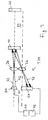
- an optical sensor 100 As a so-called web edge sensor. If in the in Fig. 1 shown embodiment, one of the monitoring sections "bright” sees, therefore, no object is in the corresponding beam path, and the other monitoring section switches to "dark", there is an object to be detected, for example, an edge of a web-like material, in a clearly defined position. If both monitoring sections see “bright", the position of the object deviates in a direction determined by the orientation of the sensor. This is in the in Fig. 2 the situation shown, for example, the case when an upper edge 12 of the object to be detected 10 drops so far that the light 22 of the light emitter 20 is no longer blocked by this edge and thus can freely reach the retroreflector 90.
- a height of an object 10 is monitored. If the object is in the in Fig. 2 situation shown is too high, both the light 22 of the light emitter 20 and the light 42 of the light emitter 40 is interrupted. On the other hand, if the object is too low, the light paths for the light 22, 42 are free. In this application, it is particularly advantageous if more than two transmitters, for example four transmitters, are used. Then a more accurate evaluation of the height of objects to be monitored is possible. The result can then be used to automatically sort the object to be detected, depending on its size, into a specific storage compartment or to transport it in different directions. Also, a direction of movement of the object 10, for example in a direction 14 transverse to the main beam directions 29, 49, with the in Fig. 2 monitored optical sensor 100 are monitored.
- optical sensor according to the invention An essential advantage of the optical sensor according to the invention is that all the above-described functionalities can in principle be integrated in a single sensor.
- the corresponding modes can be selected via switches, or a separate output is made available for each function.
- the advantage here is both the user who uses the same sensor for different applications and thus saves effort in logistics and the sensor manufacturer.
- the higher functionality ensures a higher number of pieces to be manufactured and thus lower production costs.
- Fig. 3 shows a variant in which instead of a common autocollimation optics 30, a transmitting optics 34, with the light 22, 42 is guided into the monitoring area 90, and a separate detector or receiver optics 36 is used.
- a transmitting optics 34 with the light 22, 42 is guided into the monitoring area 90, and a separate detector or receiver optics 36 is used.
- the structure corresponds to Fig. 3 in the FIGS. 1 and 2 shown situation.
- FIGS. 4 to 7 The possibilities of web edge detection are related to the FIGS. 4 to 7 explained in more detail.
- the optical sensor 100 With the optical sensor 100, the position of an edge 12 of a web-like material, for example the edge of a paper, cloth or film web, is determined.
- the sensor 100 again has two light transmitters which emit light 22 in a first channel and light 42 in a second channel.
- the object 10 to be detected is located here at a distance 24 from the optical sensor 100.
- a retroreflector 60 is arranged, which reflects or scatters the incident light 22, 42 in the direction of the sensor 100.
- the optical sensor 100 and the beam paths of the light 22, 42 of the first and the second channel are positioned with respect to the object 10 to be detected in such a way that at least part of the light 22 of the first channel is blocked by the object 10 and another part falls on the retroreflector 60.
- the sensor off Fig. 4 works accordingly as a reflection light barrier. While the object 10 with its edge 12 is in a desired position, a teach-in process is performed.
- the object 10 may, in principle, be positioned in the entire area of the light beam 22, wherein it must be ensured that the object 10 interrupts at least a small part of the light 22 and transmits at least a small portion of the light 22.
- the sensor 100 stores the amount of the detection signal reflected during the teaching operation.
- the sensor 100 evaluates the detector signal. This can be done at specific times or continuously. If a certain threshold is exceeded, the object is in a misposition, in Fig. 3 For example, in an excessively high position, that is to say, too much of the light 22 reaches the retroreflector 60 and is subsequently detected in the detector. On the other hand, if a smaller second threshold value is reached, the edge 12 of the object 10 is in Fig. 4 Too far down, that is, too much of the light 42 is obscured by the object 10 and the detection signal is correspondingly lower. A permissible range can be defined via the distance between the two threshold values. Via two outputs, which are each assigned to a specific direction, the deviation can also be transmitted to a higher-level control, which can then move the object 10 and thus the edge 12 along the arrow 80 in the correct direction.
- the senor 100 In order to keep the permissible range of the object 10 as small as possible and thus to realize a very precise positioning, the sensor 100 must be able to evaluate even very small contrasts of the received signal. Thus, for example, can be required, and this can also be realized with the aid of the invention, that even below a value of 5% to switching an output or on the other hand, an excess of 5% leads to switching the other output.
- the properties of electronic components are temperature-dependent, so that the received signal changes with temperature. For example, contamination of a front screen of the sensor or the retroreflector leads to a reduction of the received signal. The consequence of these influences would be a shift of the object positions in which the outputs switch.
- a constant readjustment of the sensitivity must be carried out. This is used in the in Fig. 4 shown example, the second, formed by the light 42 lower channel, the light path to the retroreflector 60 must be free.
- the received signal of the lower channel is not affected by the object 10 and therefore constantly registers the sum of the effects of environmental influences on the sensor 100. This information can be used to compensate for the switching behavior of the upper channel such that the spatial positions of the object, in which the sensor switches, can not be changed.
- the compensation can for example be designed so that both channels are routed via a common reception path. Its gain can then be varied so that the resulting received signal of the lower channel remains constant. Another possibility is to vary the threshold values depending on the height of the received signal of the lower channel.
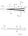
- FIGS. 5 to 7 Another way to determine the position of a web edge, with respect to the FIGS. 5 to 7 described.
- the basic idea is to align the beam paths of the light 22, 42 of the first and second channel to each other so that an overlap region 16 of the light is formed.
- the object 10 to be detected is positioned so that an edge of this object lies in the overlapping region 16 of the two channels.
- This measurement principle can be applied both using a retroreflector and during grooving operation, if the sensitivity of the evaluation is increased accordingly.
- both channels can be alternately pulsed in order to evaluate each of the received signal can.
- An edge of an object to be detected, whose position is to be evaluated, must be in the overlap area 16 of the two channels.
- the sensor 100 determines and stores the ratio of the two received signals originating from the light 22 and the light 42, respectively. During ongoing measuring operation, the ratio of these two signals is then compared with the stored learned value and evaluated.
- the advantage of this arrangement is that the distance from the sensor and the surface properties of the object to be detected 10 have essentially no influence on the location of the switching points.
- the optics should be designed for this purpose so that the overlap region 16 forms a parallel beam path with a constant diameter, as for example in Fig. 5 is shown.
- the light 22 here corresponds to a light spot 23 and the light 42 to a light spot 43.
- the light spots 23, 43 are essentially circles that overlap in a region 16.
- the return to the light 42 received signal 45 and the return to the light 22 received signal 25 are located. Underneath, the ratio 18 of these two signals 25, 45 is shown schematically. All signals are plotted against a position 80 of the edge of, for example, from the left, entering the beam path object.
- Fig. 7 shows a further embodiment in which the cross sections 23, 43 have a triangular shape, which can be realized for example with suitable aperture. This results in a significantly extended overlap region 16, in which the target position of a web edge can move.
- the specific geometry of the overlapping regions 16 can be adapted to the requirements of the individual case.
- the present invention provides a highly functional optical sensor and a particularly versatile method for detecting objects in a monitoring area, with the aid of a plurality of light sources monitoring a plurality of monitoring subareas and correspondingly controlling two or more sensor outputs.
- a movement direction of objects a position detection or a height control, preferably with a high number of transmitters, can be carried out.
- the optical sensor according to the invention is used to detect a web edge position or for web edge control. Part of these functions, or in principle all of these functions, can be integrated into a single sensor, and appropriate selection means, such as switches or several separate outputs, can be provided to activate the individual modes.
Landscapes
- Physics & Mathematics (AREA)
- Engineering & Computer Science (AREA)
- General Physics & Mathematics (AREA)
- Remote Sensing (AREA)
- Computer Networks & Wireless Communication (AREA)
- Radar, Positioning & Navigation (AREA)
- Electromagnetism (AREA)
- Life Sciences & Earth Sciences (AREA)
- General Life Sciences & Earth Sciences (AREA)
- Geophysics (AREA)
- Length Measuring Devices By Optical Means (AREA)
- Geophysics And Detection Of Objects (AREA)
- Optical Radar Systems And Details Thereof (AREA)
Applications Claiming Priority (1)
| Application Number | Priority Date | Filing Date | Title |
|---|---|---|---|
| DE102007054596A DE102007054596A1 (de) | 2007-11-15 | 2007-11-15 | Optischer Sensor und Verfahren zur Positionsbestimmung von Objekten |
Publications (2)
| Publication Number | Publication Date |
|---|---|
| EP2065732A2 true EP2065732A2 (fr) | 2009-06-03 |
| EP2065732A3 EP2065732A3 (fr) | 2010-02-17 |
Family
ID=40350096
Family Applications (1)
| Application Number | Title | Priority Date | Filing Date |
|---|---|---|---|
| EP08019966A Withdrawn EP2065732A3 (fr) | 2007-11-15 | 2008-11-14 | Capteur optique et procédé de détermination de la position d'objets |
Country Status (2)
| Country | Link |
|---|---|
| EP (1) | EP2065732A3 (fr) |
| DE (1) | DE102007054596A1 (fr) |
Cited By (1)
| Publication number | Priority date | Publication date | Assignee | Title |
|---|---|---|---|---|
| CN111579066A (zh) * | 2020-06-15 | 2020-08-25 | 深圳市灵明光子科技有限公司 | 光电探测单元、光电探测组件以及激光测距器件 |
Families Citing this family (3)
| Publication number | Priority date | Publication date | Assignee | Title |
|---|---|---|---|---|
| DE102011014195B4 (de) | 2010-03-19 | 2022-04-21 | Leuze Electronic Gmbh & Co. Kg | Optischer Sensor |
| US9857472B2 (en) | 2013-07-02 | 2018-01-02 | Electronics And Telecommunications Research Institute | Laser radar system for obtaining a 3D image |
| DE102017222769B4 (de) * | 2017-12-14 | 2019-09-26 | Jenoptik Optical Systems Gmbh | Winkelmessgerät und Verfahren zum Ermitteln eines Verkippungswinkels eines Reflexionselementes mittels eines Winkelmessgerätes |
Citations (11)
| Publication number | Priority date | Publication date | Assignee | Title |
|---|---|---|---|---|
| US4184080A (en) | 1977-06-30 | 1980-01-15 | Molins Machine Company, Inc. | Ratiometric edge detector system |
| US4716298A (en) | 1984-06-01 | 1987-12-29 | Nissan Motor Company, Limited | System for automatically detecting presence or absence of a preceding vehicle and method therefor |
| DE3919917C2 (fr) | 1989-06-19 | 1991-06-27 | Pepperl & Fuchs Gmbh, 6800 Mannheim, De | |
| DE19653312C1 (de) | 1996-12-20 | 1998-04-02 | Fife Gmbh | Vorrichtung zur Bestimmung der Lage des Randes eines laufenden Bandes |
| DE10055689A1 (de) | 2000-11-06 | 2002-05-16 | Pepperl & Fuchs Visolux Gmbh | Testbares Triangulationslichtgitter |
| EP1154225B1 (fr) | 2000-05-10 | 2004-10-27 | ERHARDT + LEIMER GmbH | Détection du bord, ou marquage, d'un ruban d'un produit en mouvement avec une deuxième source de lumière diffuse ainsi qu'un indicateur lumineux |
| EP1498747A1 (fr) | 2003-07-16 | 2005-01-19 | Leuze electronic GmbH + Co KG | Appareil optoélectronique |
| EP1528411A1 (fr) | 2003-10-27 | 2005-05-04 | Bea S.A. | Dispositif de mesure de distance |
| EP1722191A1 (fr) | 2000-11-29 | 2006-11-15 | Sick Ag | Détermination de distance |
| DE102005033349A1 (de) | 2004-08-11 | 2007-01-25 | Leuze Electronic Gmbh & Co Kg | Optischer Sensor |
| EP1832896A1 (fr) | 2006-03-10 | 2007-09-12 | Pepperl + Fuchs Gmbh | Barrière lumineuse à réflexion avec source de radiation auxiliaire destinée à la vérification d'objets dans une zone de surveillance |
-
2007
- 2007-11-15 DE DE102007054596A patent/DE102007054596A1/de not_active Withdrawn
-
2008
- 2008-11-14 EP EP08019966A patent/EP2065732A3/fr not_active Withdrawn
Patent Citations (12)
| Publication number | Priority date | Publication date | Assignee | Title |
|---|---|---|---|---|
| US4184080A (en) | 1977-06-30 | 1980-01-15 | Molins Machine Company, Inc. | Ratiometric edge detector system |
| US4716298A (en) | 1984-06-01 | 1987-12-29 | Nissan Motor Company, Limited | System for automatically detecting presence or absence of a preceding vehicle and method therefor |
| DE3919917C2 (fr) | 1989-06-19 | 1991-06-27 | Pepperl & Fuchs Gmbh, 6800 Mannheim, De | |
| DE19653312C1 (de) | 1996-12-20 | 1998-04-02 | Fife Gmbh | Vorrichtung zur Bestimmung der Lage des Randes eines laufenden Bandes |
| EP1154225B1 (fr) | 2000-05-10 | 2004-10-27 | ERHARDT + LEIMER GmbH | Détection du bord, ou marquage, d'un ruban d'un produit en mouvement avec une deuxième source de lumière diffuse ainsi qu'un indicateur lumineux |
| DE10055689A1 (de) | 2000-11-06 | 2002-05-16 | Pepperl & Fuchs Visolux Gmbh | Testbares Triangulationslichtgitter |
| EP1722191A1 (fr) | 2000-11-29 | 2006-11-15 | Sick Ag | Détermination de distance |
| EP1498747A1 (fr) | 2003-07-16 | 2005-01-19 | Leuze electronic GmbH + Co KG | Appareil optoélectronique |
| EP1528411A1 (fr) | 2003-10-27 | 2005-05-04 | Bea S.A. | Dispositif de mesure de distance |
| DE102005033349A1 (de) | 2004-08-11 | 2007-01-25 | Leuze Electronic Gmbh & Co Kg | Optischer Sensor |
| EP1832896A1 (fr) | 2006-03-10 | 2007-09-12 | Pepperl + Fuchs Gmbh | Barrière lumineuse à réflexion avec source de radiation auxiliaire destinée à la vérification d'objets dans une zone de surveillance |
| DE102006011250A1 (de) | 2006-03-10 | 2007-09-13 | Pepperl + Fuchs Gmbh | Reflexionslichtschranke zum Nachweis von Objekten in einem Überwachungsbereich und Verfahren zu deren Betrieb |
Cited By (1)
| Publication number | Priority date | Publication date | Assignee | Title |
|---|---|---|---|---|
| CN111579066A (zh) * | 2020-06-15 | 2020-08-25 | 深圳市灵明光子科技有限公司 | 光电探测单元、光电探测组件以及激光测距器件 |
Also Published As
| Publication number | Publication date |
|---|---|
| EP2065732A3 (fr) | 2010-02-17 |
| DE102007054596A1 (de) | 2009-05-20 |
Similar Documents
| Publication | Publication Date | Title |
|---|---|---|
| EP2453252B1 (fr) | Capteur 3D à économie d'énergie | |
| EP1355128B1 (fr) | Alignement automatique d'un senseur | |
| EP0892280A2 (fr) | Procédé pour faire fonctionner un dispositif capteur opto-électronique | |
| DE10301971A1 (de) | Positionsbestimmungsvorrichtung | |
| EP0379097B1 (fr) | Procédé pour déterminer la position d'un bord et capteur photoélectrique pour cette détermination | |
| DE102007003024A1 (de) | Triangulationssensor mit Entfernungsbestimmung aus Lichtfleckposition und -form | |
| DE19911375A1 (de) | Einrichtung zur Detektion der Position eines Flugkörpers | |
| DE202005007089U1 (de) | Sensoranordnung zur optischen Kantendetektierung einer Ware | |
| EP2065732A2 (fr) | Capteur optique et procédé de détermination de la position d'objets | |
| DE102004010566A1 (de) | Tastkopf für ein Koordinatenmessgerät | |
| DE19914962C2 (de) | Optoelektronische Vorrichtung | |
| WO2010063521A2 (fr) | Système et procédé de mesure optique | |
| DE102004003386B4 (de) | Optischer Sensor | |
| WO2011038804A1 (fr) | Capteur optique | |
| EP2851704B1 (fr) | Dispositif et procédé de détermination optique de distances par rapport à des objets dans une zone de surveillance | |
| WO2013149887A1 (fr) | Capteur optique pour un dispositif d'éclairage, système d'éclairage comportant au moins un capteur optique et procédé de réglage de la luminosité d'un système d'éclairage comportant au moins un capteur optique | |
| DE102021112212A1 (de) | Optischer Sensor und Verfahren zum Betrieb eines optische Sensors | |
| EP4465079B1 (fr) | Capteur optique de distance | |
| EP1148352B1 (fr) | Capteur optique | |
| DE3336726A1 (de) | Kantenfuehlvorrichtung | |
| DE202006003841U1 (de) | Vorrichtung zum Nachweis von Objekten | |
| WO2006092300A2 (fr) | Systeme de capteurs destine a la detection d'arete optique d'un produit et procede de determination de largeur | |
| EP4506719A1 (fr) | Capteur | |
| DE2448571C3 (de) | Anordnung zum berührungslosen Messen der Abmessung, wie z.B. Durchmesser, Querschnitt o.dgl. eines Objekts | |
| EP1278051A1 (fr) | Ensemble de lentilles pour senseur de mouvement |
Legal Events
| Date | Code | Title | Description |
|---|---|---|---|
| PUAI | Public reference made under article 153(3) epc to a published international application that has entered the european phase |
Free format text: ORIGINAL CODE: 0009012 |
|
| AK | Designated contracting states |
Kind code of ref document: A2 Designated state(s): AT BE BG CH CY CZ DE DK EE ES FI FR GB GR HR HU IE IS IT LI LT LU LV MC MT NL NO PL PT RO SE SI SK TR |
|
| AX | Request for extension of the european patent |
Extension state: AL BA MK RS |
|
| PUAL | Search report despatched |
Free format text: ORIGINAL CODE: 0009013 |
|
| AK | Designated contracting states |
Kind code of ref document: A3 Designated state(s): AT BE BG CH CY CZ DE DK EE ES FI FR GB GR HR HU IE IS IT LI LT LU LV MC MT NL NO PL PT RO SE SI SK TR |
|
| AX | Request for extension of the european patent |
Extension state: AL BA MK RS |
|
| RIC1 | Information provided on ipc code assigned before grant |
Ipc: G01B 11/02 20060101ALI20100108BHEP Ipc: G01S 17/06 20060101AFI20090220BHEP |
|
| 17P | Request for examination filed |
Effective date: 20100810 |
|
| 17Q | First examination report despatched |
Effective date: 20100907 |
|
| AKX | Designation fees paid |
Designated state(s): AT BE BG CH CY CZ DE DK EE ES FI FR GB GR HR HU IE IS IT LI LT LU LV MC MT NL NO PL PT RO SE SI SK TR |
|
| STAA | Information on the status of an ep patent application or granted ep patent |
Free format text: STATUS: THE APPLICATION IS DEEMED TO BE WITHDRAWN |
|
| 18D | Application deemed to be withdrawn |
Effective date: 20120614 |