EP4465079A1 - Capteur optique de distance - Google Patents
Capteur optique de distance Download PDFInfo
- Publication number
- EP4465079A1 EP4465079A1 EP23173936.8A EP23173936A EP4465079A1 EP 4465079 A1 EP4465079 A1 EP 4465079A1 EP 23173936 A EP23173936 A EP 23173936A EP 4465079 A1 EP4465079 A1 EP 4465079A1
- Authority
- EP
- European Patent Office
- Prior art keywords
- light beams
- pilot
- distance sensor
- optical distance
- light
- Prior art date
- Legal status (The legal status is an assumption and is not a legal conclusion. Google has not performed a legal analysis and makes no representation as to the accuracy of the status listed.)
- Granted
Links
Images


Classifications
-
- G—PHYSICS
- G01—MEASURING; TESTING
- G01S—RADIO DIRECTION-FINDING; RADIO NAVIGATION; DETERMINING DISTANCE OR VELOCITY BY USE OF RADIO WAVES; LOCATING OR PRESENCE-DETECTING BY USE OF THE REFLECTION OR RERADIATION OF RADIO WAVES; ANALOGOUS ARRANGEMENTS USING OTHER WAVES
- G01S7/00—Details of systems according to groups G01S13/00, G01S15/00, G01S17/00
- G01S7/48—Details of systems according to groups G01S13/00, G01S15/00, G01S17/00 of systems according to group G01S17/00
- G01S7/481—Constructional features, e.g. arrangements of optical elements
- G01S7/4814—Constructional features, e.g. arrangements of optical elements of transmitters alone
-
- G—PHYSICS
- G01—MEASURING; TESTING
- G01S—RADIO DIRECTION-FINDING; RADIO NAVIGATION; DETERMINING DISTANCE OR VELOCITY BY USE OF RADIO WAVES; LOCATING OR PRESENCE-DETECTING BY USE OF THE REFLECTION OR RERADIATION OF RADIO WAVES; ANALOGOUS ARRANGEMENTS USING OTHER WAVES
- G01S17/00—Systems using the reflection or reradiation of electromagnetic waves other than radio waves, e.g. lidar systems
- G01S17/02—Systems using the reflection of electromagnetic waves other than radio waves
- G01S17/06—Systems determining position data of a target
- G01S17/08—Systems determining position data of a target for measuring distance only
- G01S17/10—Systems determining position data of a target for measuring distance only using transmission of interrupted, pulse-modulated waves
-
- G—PHYSICS
- G01—MEASURING; TESTING
- G01S—RADIO DIRECTION-FINDING; RADIO NAVIGATION; DETERMINING DISTANCE OR VELOCITY BY USE OF RADIO WAVES; LOCATING OR PRESENCE-DETECTING BY USE OF THE REFLECTION OR RERADIATION OF RADIO WAVES; ANALOGOUS ARRANGEMENTS USING OTHER WAVES
- G01S7/00—Details of systems according to groups G01S13/00, G01S15/00, G01S17/00
- G01S7/48—Details of systems according to groups G01S13/00, G01S15/00, G01S17/00 of systems according to group G01S17/00
- G01S7/481—Constructional features, e.g. arrangements of optical elements
- G01S7/4814—Constructional features, e.g. arrangements of optical elements of transmitters alone
- G01S7/4815—Constructional features, e.g. arrangements of optical elements of transmitters alone using multiple transmitters
-
- G—PHYSICS
- G01—MEASURING; TESTING
- G01S—RADIO DIRECTION-FINDING; RADIO NAVIGATION; DETERMINING DISTANCE OR VELOCITY BY USE OF RADIO WAVES; LOCATING OR PRESENCE-DETECTING BY USE OF THE REFLECTION OR RERADIATION OF RADIO WAVES; ANALOGOUS ARRANGEMENTS USING OTHER WAVES
- G01S7/00—Details of systems according to groups G01S13/00, G01S15/00, G01S17/00
- G01S7/48—Details of systems according to groups G01S13/00, G01S15/00, G01S17/00 of systems according to group G01S17/00
- G01S7/497—Means for monitoring or calibrating
- G01S7/4972—Alignment of sensor
Definitions
- the invention relates to an optical distance sensor.
- Such optical distance sensors are used to determine the distance of objects and are used for various measuring or monitoring tasks.
- the optical distance sensors can carry out distance measurements in particular using a pulse-time of flight method.
- the optical distance sensor has a transmitter that emits light beams and sends them into a monitoring area.
- the light beams are reflected by an object to be detected in the monitoring area and guided back to a receiver of the optical distance sensor.
- the distance is determined based on an evaluation of received signals from the receiver in such a way that the time of flight of the light pulses to the object and back to the receiver is determined.
- time-of-flight modules are advantageously used for distance measurement. These have a VCSEL (vertical-cavity surface-emitting laser) diode or a VCSEL array that emits laser light in the infrared range as a transmitter.
- the VCSEL array consists of VCSELs arranged as close together as possible on a chip.
- the time-of-flight modules usually have an array of SPADs (single photon avalanche diodes) as a receiver. These time-of-flight modules have high performance despite their small size.
- visible light beams are required in numerous applications, in particular to be able to optically control the beam guidance of the light beams or to simplify the adjustment of the optical distance sensors during their commissioning.
- time-of-flight modules with VCSEL diodes or VCSEL arrays that emit light rays in the visible wavelength range can be used to meet this requirement.
- the invention is based on the object of providing an optical distance sensor of the type mentioned above, which on the one hand has a high detection sensitivity and on the other hand enables a visual control of the guidance of its light beams.
- the invention relates to an optical distance sensor with a transmitter that emits light beams in a non-visible wavelength range, with a receiver that is designed to receive the light beams reflected back from an object, and with an evaluation unit that is designed to determine the distance of the object depending on reception signals from the receiver.
- a pilot transmitter unit is provided that emits visible pilot light beams, wherein the pilot light beams are coupled into the beam path of the light beams by means of coupling means such that the Pilot light beams and light beams with at least partially overlapping beam cross-sections run coaxially.
- optical distance sensor With the optical distance sensor according to the invention or with the method for operating this optical distance sensor, a high level of sensor functionality is realized.
- the transmitter of the optical distance sensor emits light rays in the non-visible wavelength range, in particular in the infrared range. This ensures that the optical sensor has a high detection sensitivity when detecting objects in a monitoring area.
- the optical distance sensor has a significantly increased resistance to external light compared to an optical distance sensor whose transmitter emits light rays in the visible wavelength range.
- the optical distance sensor has a pilot transmitter unit that emits pilot light beams in the visible wavelength range.
- the pilot light beams are coupled into the beam path by coupling means in such a way that the pilot light beams and the light beams run coaxially, at least partially overlapping, the coaxial course being advantageously maintained in the entire monitoring area.
- the visible pilot light beams are used to visualize the measuring invisible light beams, i.e. a user can use the pilot light beams to see the path of the measuring invisible light beams and can thus check the path of the light beams. This can be used to adjust the optical distance sensor before it is put into operation. The user can also continuously check the path of the light beams during operation following the adjustment.
- pilot light beams are not offset laterally, but run coaxially to the light beams.
- pilot light beams offset laterally a user would have to use additional measuring equipment to determine the course of the invisible light beams based on the visible pilot light beams. This effort is not necessary with the optical distance sensors according to the invention, since the pilot light beams run coaxially to the light beams, so that the pilot light beams immediately and directly provide the desired information about the spatial course of the light beams.
- the pilot transmitter unit and the coupling means are designed in such a way that the light beams and the pilot light beams not only run coaxially in the entire monitoring area, but also have approximately the same beam cross-section.
- the pilot transmitter unit can emit diffuse or directed, in particular collimated pilot light beams, wherein the beam characteristics are advantageously adapted to the beam characteristics of the light beams.
- the distance measurement in the optical distance sensor according to the invention can be carried out using a phase measurement method.
- the transmitter emits light beams in the form of light pulses.
- the distance measurement is then carried out using a pulse-time-of-flight method.
- the transmitter is particularly advantageously a VCSEL unit.
- the VCSEL unit can be formed by a VCSEL diode that emits only one, preferably directed, light beam. Furthermore, the VCSEL unit can be formed by a VCSEL array that emits multiple light beams. With this embodiment, a large opening angle of the emitted light beams can be achieved and the total emitted optical power increases, which improves the performance of the measuring system.
- the receiver is designed in the form of one or more SPADs (single photon avalanche diodes).
- a laser diode edge emitter
- a transmitted light source with infrared radiation can also be used as a transmitted light source with infrared radiation. This allows small light spots with high irradiance to be created.
- the transmitter and the pilot transmission unit are each formed by a semiconductor chip, wherein the semiconductor chips are arranged one above the other and fixed relative to one another.
- the semiconductor chip forming the transmitter can be arranged on top of the semiconductor chip forming the pilot transmission unit, wherein the semiconductor chip forming the transmitter has a hole in the middle as a coupling means through which the pilot transmission unit emits the pilot light beams, which then run coaxially to the light beams of the transmitter.
- the reverse arrangement can also be provided, in which the semiconductor chip lying on top and having a hole forms the pilot transmission unit, wherein the transmitter emits the light beams through the hole of the semiconductor chip forming the pilot transmission unit.
- a material that converts the infrared light rays of the transmitter into visible pilot light rays can be applied to the light-emitting surface of the transmitter, which is designed in the form of a semiconductor chip, in particular in the form of a VCSEL array.
- the material does not extend over the entire light-emitting surface of the transmitter, so that the transmitter sends infrared light rays into the monitoring area in the uncovered areas.
- optical fibers are provided as coupling means.
- the optical fibers are preferably placed around the transmitter so that pilot light beams emitted by the pilot transmitter unit are coupled parallel to the beam path of the light beams via the optical fibers.
- the optical fibers can also be formed in particular in the form of glass fibers.
- an optical deflection element is provided as the coupling means.
- the optical deflection element generally deflects pilot light beams from the pilot transmitter unit in such a way that the pilot light beams are coaxially coupled into the beam path of the light beams.
- the optical deflection element is a dichroic mirror or forms an interference filter.
- the optical deflection element therefore has wavelength-selective properties.
- the optical deflection element can be designed in the form of a coated glass pane.
- the optical deflection element can be a purely reflective element or can also be designed in the form of a beam splitter mirror, which in particular reflected in a first wavelength range and is permeable to light in a second wavelength range.
- the optical deflection element can be designed in such a way that it only reflects certain areas of the incident pilot light beams. This makes it possible to generate certain patterns of the pilot light beams, for example in the form of rectangles, rings or several points.
- the size of the light spot of the pilot light beams is adapted to the size of the light spot of the light beams by means of an aperture.
- the aperture can in particular be arranged directly in front of the pilot transmitter unit. Alternatively, the aperture can be arranged at a distance from the pilot transmitter unit.
- a variable aperture is provided, by means of which a beam formation of the pilot light beams takes place in such a way that a part of the light spot of the light beams is illuminated with them.
- variable aperture can be designed in the form of a TFT (thin-film transistor) matrix, in which individual matrix elements can be switched to be transparent or opaque. This allows the size and shape of the aperture opening to be specified quickly and precisely.
- TFT thin-film transistor
- the opening angle of the pilot light beams can be changed by varying the size of the diaphragm opening in order to adapt it to the actual field of view of the receiver, especially SPAD arrays, depending on the measured distance.
- the pilot light spot is no longer adjusted to the size of the transmitted light spot.
- variable aperture is particularly advantageous when used in combination with a transmitter that emits light beams at a large opening angle.
- the transmitter is then preferably formed by a VCSEL array.
- the light beams then cover a large measuring area.
- the variable aperture can then be used to specifically mark individual parts of the measuring area, i.e. to visualize them, for example the parts within which objects are to be detected.
- a controllable lens is provided, by means of which the course of the pilot light rays is adapted to the course of the light rays.
- the lens can be controlled in particular depending on measured distance values in order to adapt the light spot of the pilot light beams to the respective object distance.
- the lens can be controlled so that the size of the light spot of the pilot light beams corresponds to the size of the light spot of the light beams in the entire monitoring area.
- an adjustment mechanism is provided which is designed to change the beam direction of the pilot light beams.
- the beam direction of the pilot light beams is specified in an adjustment process during device assembly in such a way that the pilot light beams can then be coupled into the beam path of the light beams using the coupling means in such a way that the pilot light beams and light beams run coaxially.
- the adjustment mechanism is particularly advantageously implemented by means of a pivot bearing, with which the direction of the pilot light beams can be adjusted in one or two spatial directions.
- the pilot transmitter unit is arranged on a circuit board that can be pivoted by means of a pivot bearing.
- fixing means are available to permanently fix an optimized position found during an adjustment, particularly the swivel position of the pilot transmitter unit. Soldered and adhesive connections are suitable as fixing means.
- switching means are provided by means of which the pilot transmitter unit can be switched on and off.
- the pilot transmitter unit can then be activated only in specific time periods in which visualization of the light beams with the pilot light beams is required.
- the activation and deactivation of the pilot transmitter unit can be carried out by entering control signals into the optical distance sensor or by operating a control element on the optical distance sensor.
- the pilot transmitter unit can remain activated for a preset time after an operator-guided activation.
- the functionality of the optical distance sensor can be further extended by using the pilot light beams as a display device for displaying sensor information.
- the sensor information to be displayed can be status states, especially error states.
- the optical distance sensor can also be designed in such a way that, depending on the determined distance values, a binary switching signal is generated, the switching states of which indicate whether an object is present within a given distance range or not.
- the switching states of the switching signal can then be displayed as sensor information.
- different sensor information can be displayed using different colors of the pilot light beams, whereby different colors of the pilot light beams can be generated by the pilot transmitter unit having several transmitter elements that emit light in different colors.
- the pilot transmitter unit can have two transmitter elements, for example in the form of light-emitting diodes, with which pilot light beams are generated in different colors.
- the coupling means can be used to guide the beam in such a way that the differently colored pilot light beams run parallel to one another. Different sensor information can then be displayed by activating both transmitter elements or just one of the transmitter elements.
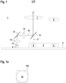
- Figure 1 shows schematically components of a first embodiment of the optical distance sensor 1 according to the invention.
- the optical distance sensor 1 With the optical distance sensor 1 according to Figure 1 and according to all the following embodiments, the distance of objects within a monitoring area is determined.
- the distance measurements are carried out using a pulse-travel time method.
- the optical distance sensor 1 generally has a transmitter 3 that emits light rays 2 and a receiver 4 that receives light rays 2.
- the transmitter 3 emits light rays 2 in the non-visible wavelength range.
- the transmitter 3 emits the light rays 2 in the form of light pulses.
- the travel time of the light pulses emitted by the transmitter 3 to an object and back to the receiver 4 is used to determine the distance.
- the distance is determined in an evaluation unit (not shown) depending on the received signals at the output of the receiver 4.
- the optical distance sensor 1 can output the distance value directly via an output (not shown).
- the evaluation unit generates a binary switching signal as an output signal depending on the determined distance values, the switching states of which indicate whether an object is located within a specified monitoring area.
- the transmitter 3 is advantageously formed by an infrared light emitting diode, in particular a laser diode.
- the transmitter 3 is particularly advantageously formed by a VCSEL diode.
- the receiver 4 advantageously consists of one or more SPADs (singlephoton avalanche diodes).
- the evaluation unit consists of a processor system, which in the simplest case can be formed by a single processor.
- the processor system can also have a multi-channel processor arrangement, in particular if the optical distance sensor 1 is a safety sensor.
- a transmitting optic in the form of a transmitting lens 7 is arranged downstream of the transmitter 3. This produces collimated light beams 2.
- a receiving optic in the form of a receiving lens 8 is arranged upstream of the receiver 4.
- the optical distance sensor 1 (in all embodiments) is provided with a pilot transmitter unit 9 that emits visible pilot light beams 10.
- the pilot transmitter unit 9 emits green light.
- the pilot transmitter unit 9 can also emit pilot light beams 10 of a different color, in particular red.
- the pilot transmission unit 9 can, for example, consist of a light-emitting diode arrangement, which can comprise one or more light-emitting diodes.
- pilot transmitter unit 9 is mounted on the same circuit board 6 on which the runtime module 5 is mounted.
- a diaphragm 11 is mounted on the pilot transmitter unit 9, with which the size of the light spot 2a of the pilot light beams 10 is adapted to the size of the light spot 2a of the light beams 2.
- the diaphragm 11 can be located at a distance from the pilot transmitter unit 9.
- a variable diaphragm 11 can be used, in particular in the form of a TFT matrix.
- coupling means are provided by means of which the pilot light beams 10 are coupled into the beam path of the light beams 2 in such a way that the pilot light beams 10 and light beams 2 run coaxially, preferably within the entire monitoring area.
- Figure 1a shows in a sectional view the light spot 2a of the light rays 2 and the light spot 10a of the pilot light rays 10. As can be seen from Figure 1a Obviously, these light spots 2a, 10a partially overlap.
- a deflection mirror 12 and a deflection element 13 in the form of a dichroic mirror are provided as coupling means.
- the pilot light beams 10 are reflected on the deflection mirror 12.
- the dichroic mirror has a wavelength-dependent characteristic and reflects the pilot light beams 10.
- the dichroic mirror is transparent to the light beams 2.
- a first lens 14 is located between the pilot transmitter unit 9 and the deflection mirror 12.
- a second lens 15 is located between the deflection mirror 12 and the dichroic mirror.
- the lenses 14, 15 are preferably controllable in order to be able to variably adjust the course of the pilot light beams 10 in the monitoring area.
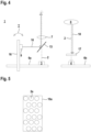
- FIG. 2 shows a further embodiment of the optical distance sensor 1.
- the pilot transmitter unit 9 is arranged on a further circuit board 16, which is pivotably mounted on the first circuit board 6.
- the circuit board 16 By pivoting the circuit board 16 (illustrated with the double arrow I), the direction of the visible pilot light beams 10 emitted by the pilot transmitter unit 9 can be adjusted.
- a diaphragm 11 is again mounted on the pilot transmitting unit 9.
- the only coupling means provided is the dichroic mirror, through which the pilot light beams 10 are coupled in coaxially to the light beams 2.
- FIG 3 shows a variant of the embodiment according to Figure 2 .
- the transmitter 3 and the receiver 4 form spatially separate units in this case.
- the transmitter 3 with the further circuit board 16, which carries the pilot transmitter unit 9, is located on a first circuit board 6a, the receiver 4 on a second circuit board 6b.
- the pilot light beams 10 are again coupled into the beam path of the light beams 2 via a dichroic mirror.
- a lens 15 is located between the pilot transmitter unit 9, possibly with a front aperture 11 (not shown), and the dichroic mirror.
- the transmitting lens 7 is located between the transmitter 3 and the dichroic mirror.
- an optical filter 17 which filters out the pilot light beams 10 and ambient light so that only light beams 2 hit the receiver 4.
- Such an optical filter 17 can also be used in the embodiments according to the Figures 1 and 2 to be available.
- Figure 4 shows a variant of the embodiment according to Figure 3
- the transmitting lens 7 is arranged in the beam path of the light rays 2 behind the dichroic mirror and also serves to shape the beam of the pilot light rays 10 so that the lens 15 can be omitted.
- Figure 5 shows a variant of the transmitter 3 in the form of a VCSEL array that generates several light beams 2, where Figure 5 whose light spots 2a are shown in a sectional view.
- the light spot 10a of the pilot light beams 10 surrounds these light spots 2a.
- the light beams 2 and pilot light beams 10 run coaxially.
- the optical distance sensor 1 can have a structure according to the Figures 1 , 2 , 3 or 4 have.
- the Figures 6a, 6b show embodiments of deflection elements 13 in the form of geometric beam splitters, which have reflecting surfaces 18 on a transparent glass carrier 19.
- the transparent glass carrier is permeable to the light rays 2.
- the pilot light rays 10 are reflected at the reflecting surfaces 18, whereby specific beam patterns of the pilot light rays 10 can be generated according to the formation of the reflecting surfaces 18.
- the transmitter 3 in the form of a VCSEL array with specially built optics, a large opening angle in the form of a VCSEL array of the light beams 2 can be realized, since sufficient transmission power is available so that the irradiance on the object is large and accurate, as in Figure 7 shown.
- variable aperture 11 in the form of a TFT matrix is arranged downstream of the pilot transmitter unit 9.
- individual areas 20 of the light beams 2 can be visualized and thus marked, such as Figure 7 shows.
- Figure 8 shows an extension of the embodiment according to Figure 1 .
- the embodiment according to Figure 8 differs from the embodiment according to Figure 1 in that in addition to the pilot transmission unit 9 emitting pilot light beams 10, there is another pilot transmission unit 9' which emits further pilot light beams 10'. A diaphragm 11' and a lens 14' are also arranged downstream of the further pilot transmission unit 9'.
- the pilot transmission units 9, 9' emit pilot light beams 10, 10' with different colors. In the present case, the pilot transmission unit 9 emits green pilot light beams 10 and the pilot transmission unit 9' emits red pilot light beams 10'.
- pilot light beams 10, 10' of both pilot transmitter units 9, 9' are each deflected via a deflection mirror 12, 12' and guided to the dichroic mirror.
- the pilot light beams 10 run coaxially to the light beams 2 and the further pilot light beams 10' laterally offset therefrom, like the corresponding light spots 2a of the light beams 2 and the light spots 10a, 10a' of the pilot light beams 10, 10' according to Figure 9 show.
- Different sensor information can be displayed using the different pilot light beams 10, 10' and their different colors.
- different sensor information can be displayed by different flashing frequencies of the pilot light beams 10, 10'.
- the optical distance sensor 1 has switching means by means of which the pilot transmission unit 9, 9' can be switched on and off.
- the or each pilot transmission unit 9, 9' can thus be activated for certain periods of time.
- the switching means can be formed by control signals that can be read into the optical distance sensor 1 or by operating elements on the optical distance sensor 1.
- the or each pilot transmitter unit 9, 9' can be activated using the switching means.
- the pilot transmitter unit 9, 9' can then remain active for a preset time.
- the pilot transmitter unit 9, 9' can be switched off using the switching means.
- Figure 8a shows a variant of the embodiment according to Figure 8 In this case, the pilot light beams 10, 10' are guided together via the deflection mirror 12, 12'.
- FIGS 10 and 11a, 11b show schematically coupling means in the form of optical fibers 21 with which the pilot light beams 10, 10' of the pilot transmission units 9, 9' are coupled into the beam path of the light beams 2, so that the pilot light beams 10, 10' run coaxially to the light beams 2.
Landscapes
- Engineering & Computer Science (AREA)
- Physics & Mathematics (AREA)
- Computer Networks & Wireless Communication (AREA)
- General Physics & Mathematics (AREA)
- Radar, Positioning & Navigation (AREA)
- Remote Sensing (AREA)
- Electromagnetism (AREA)
- Optical Radar Systems And Details Thereof (AREA)
Priority Applications (1)
| Application Number | Priority Date | Filing Date | Title |
|---|---|---|---|
| EP23173936.8A EP4465079B1 (fr) | 2023-05-17 | 2023-05-17 | Capteur optique de distance |
Applications Claiming Priority (1)
| Application Number | Priority Date | Filing Date | Title |
|---|---|---|---|
| EP23173936.8A EP4465079B1 (fr) | 2023-05-17 | 2023-05-17 | Capteur optique de distance |
Publications (2)
| Publication Number | Publication Date |
|---|---|
| EP4465079A1 true EP4465079A1 (fr) | 2024-11-20 |
| EP4465079B1 EP4465079B1 (fr) | 2026-04-08 |
Family
ID=86426064
Family Applications (1)
| Application Number | Title | Priority Date | Filing Date |
|---|---|---|---|
| EP23173936.8A Active EP4465079B1 (fr) | 2023-05-17 | 2023-05-17 | Capteur optique de distance |
Country Status (1)
| Country | Link |
|---|---|
| EP (1) | EP4465079B1 (fr) |
Citations (2)
| Publication number | Priority date | Publication date | Assignee | Title |
|---|---|---|---|---|
| DE102020106041A1 (de) * | 2020-03-05 | 2021-09-09 | Sick Ag | Optoelektronischer Sensor |
| DE202021106330U1 (de) * | 2021-11-19 | 2023-02-27 | Sick Ag | Optoelektronischer Sensor |
-
2023
- 2023-05-17 EP EP23173936.8A patent/EP4465079B1/fr active Active
Patent Citations (2)
| Publication number | Priority date | Publication date | Assignee | Title |
|---|---|---|---|---|
| DE102020106041A1 (de) * | 2020-03-05 | 2021-09-09 | Sick Ag | Optoelektronischer Sensor |
| DE202021106330U1 (de) * | 2021-11-19 | 2023-02-27 | Sick Ag | Optoelektronischer Sensor |
Also Published As
| Publication number | Publication date |
|---|---|
| EP4465079B1 (fr) | 2026-04-08 |
Similar Documents
| Publication | Publication Date | Title |
|---|---|---|
| EP1405037B1 (fr) | Dispositif de mesure optique de distance sur une plage de mesure etendue | |
| DE10336458B4 (de) | System zur Abstandsmessung mittels Lichtquellen | |
| EP1395853B1 (fr) | Dispositif de mesure optique de distances | |
| DE3513671C2 (fr) | ||
| DE102019107568A1 (de) | Kohärentes lidar-system mit erweitertem sichtfeld | |
| EP1927014B1 (fr) | Appareil de mesure electrooptique | |
| EP1355128A1 (fr) | Alignement automatique d'un senseur | |
| EP2002208A1 (fr) | Dispositif de mesure optique de distances et son procédé de fonctionnement | |
| EP1480015A1 (fr) | Procédé et dispositif pour mesurer un signal optique modulé | |
| EP3699640B1 (fr) | Capteur optoélectronique et procédé de détection d'un objet | |
| CH699818B1 (de) | Optoelektronischer Sensor mit einem Lichtsender. | |
| EP1303738B1 (fr) | Dispositif de mesure optique de distance ou de vitesse | |
| EP1049609B1 (fr) | Dispositif pour la surveillance de l'etat d'une vitre de fenetre | |
| EP3859379A1 (fr) | Capteur optoélectronique avec filtre de réception adapté à l'angle de vue et procédé de détection des objets | |
| EP3193195A1 (fr) | Capteur optique | |
| DE102020109596A1 (de) | Optoelektronischer Sensor mit Blende und Herstellungsverfahren dafür | |
| DE102007045334A1 (de) | Messsystem | |
| DE10125885B4 (de) | Sensorvorrichtung zur schnellen optischen Abstandsmessung nach dem konfokalen optischen Abbildungsprinzip | |
| DE102020106041A1 (de) | Optoelektronischer Sensor | |
| EP4465079B1 (fr) | Capteur optique de distance | |
| EP3491413A1 (fr) | Ensemble optique pour système lidar, système lidar et dispositif de travail | |
| DE102021130334A1 (de) | Optoelektronischer Sensor | |
| DE102015115016B4 (de) | Lichtkontrasttaster | |
| EP1959271B1 (fr) | Agencement de capteur optoélectrique et procédé de vérification du mode de fonctionnement et/ou de l'ajustement d'un agencement de capteur optoélectronique | |
| EP2065732A2 (fr) | Capteur optique et procédé de détermination de la position d'objets |
Legal Events
| Date | Code | Title | Description |
|---|---|---|---|
| PUAI | Public reference made under article 153(3) epc to a published international application that has entered the european phase |
Free format text: ORIGINAL CODE: 0009012 |
|
| STAA | Information on the status of an ep patent application or granted ep patent |
Free format text: STATUS: REQUEST FOR EXAMINATION WAS MADE |
|
| 17P | Request for examination filed |
Effective date: 20231218 |
|
| AK | Designated contracting states |
Kind code of ref document: A1 Designated state(s): AL AT BE BG CH CY CZ DE DK EE ES FI FR GB GR HR HU IE IS IT LI LT LU LV MC ME MK MT NL NO PL PT RO RS SE SI SK SM TR |
|
| P01 | Opt-out of the competence of the unified patent court (upc) registered |
Free format text: CASE NUMBER: APP_62391/2024 Effective date: 20241122 |
|
| GRAP | Despatch of communication of intention to grant a patent |
Free format text: ORIGINAL CODE: EPIDOSNIGR1 |
|
| STAA | Information on the status of an ep patent application or granted ep patent |
Free format text: STATUS: GRANT OF PATENT IS INTENDED |
|
| GRAS | Grant fee paid |
Free format text: ORIGINAL CODE: EPIDOSNIGR3 |
|
| INTG | Intention to grant announced |
Effective date: 20260123 |
|
| GRAA | (expected) grant |
Free format text: ORIGINAL CODE: 0009210 |
|
| STAA | Information on the status of an ep patent application or granted ep patent |
Free format text: STATUS: THE PATENT HAS BEEN GRANTED |
|
| AK | Designated contracting states |
Kind code of ref document: B1 Designated state(s): AL AT BE BG CH CY CZ DE DK EE ES FI FR GB GR HR HU IE IS IT LI LT LU LV MC ME MK MT NL NO PL PT RO RS SE SI SK SM TR |
|
| REG | Reference to a national code |
Ref country code: CH Ref legal event code: F10 Free format text: ST27 STATUS EVENT CODE: U-0-0-F10-F00 (AS PROVIDED BY THE NATIONAL OFFICE) Effective date: 20260408 Ref country code: GB Ref legal event code: FG4D Free format text: NOT ENGLISH |