EP2065909B1 - Kippschalter - Google Patents
Kippschalter Download PDFInfo
- Publication number
- EP2065909B1 EP2065909B1 EP08170181A EP08170181A EP2065909B1 EP 2065909 B1 EP2065909 B1 EP 2065909B1 EP 08170181 A EP08170181 A EP 08170181A EP 08170181 A EP08170181 A EP 08170181A EP 2065909 B1 EP2065909 B1 EP 2065909B1
- Authority
- EP
- European Patent Office
- Prior art keywords
- contact
- contacts
- fixed
- reverse
- actuator
- Prior art date
- Legal status (The legal status is an assumption and is not a legal conclusion. Google has not performed a legal analysis and makes no representation as to the accuracy of the status listed.)
- Not-in-force
Links
- 210000000078 claw Anatomy 0.000 claims description 19
- 238000010586 diagram Methods 0.000 description 8
- 238000005192 partition Methods 0.000 description 4
- 238000012856 packing Methods 0.000 description 2
- 238000009987 spinning Methods 0.000 description 2
- 241000219122 Cucurbita Species 0.000 description 1
- 235000009852 Cucurbita pepo Nutrition 0.000 description 1
- 230000005540 biological transmission Effects 0.000 description 1
- 239000000428 dust Substances 0.000 description 1
- 238000005516 engineering process Methods 0.000 description 1
- 238000009413 insulation Methods 0.000 description 1
- 239000002184 metal Substances 0.000 description 1
- 239000011347 resin Substances 0.000 description 1
- 229920005989 resin Polymers 0.000 description 1
- 238000000926 separation method Methods 0.000 description 1
Images






Classifications
-
- H—ELECTRICITY
- H01—ELECTRIC ELEMENTS
- H01H—ELECTRIC SWITCHES; RELAYS; SELECTORS; EMERGENCY PROTECTIVE DEVICES
- H01H9/00—Details of switching devices, not covered by groups H01H1/00 - H01H7/00
- H01H9/02—Bases, casings, or covers
- H01H9/06—Casing of switch constituted by a handle serving a purpose other than the actuation of the switch, e.g. by the handle of a vacuum cleaner
- H01H9/063—Casing of switch constituted by a handle serving a purpose other than the actuation of the switch, e.g. by the handle of a vacuum cleaner enclosing a reversing switch
-
- H—ELECTRICITY
- H01—ELECTRIC ELEMENTS
- H01H—ELECTRIC SWITCHES; RELAYS; SELECTORS; EMERGENCY PROTECTIVE DEVICES
- H01H9/00—Details of switching devices, not covered by groups H01H1/00 - H01H7/00
- H01H9/30—Means for extinguishing or preventing arc between current-carrying parts
- H01H9/38—Auxiliary contacts on to which the arc is transferred from the main contacts
-
- H—ELECTRICITY
- H01—ELECTRIC ELEMENTS
- H01H—ELECTRIC SWITCHES; RELAYS; SELECTORS; EMERGENCY PROTECTIVE DEVICES
- H01H9/00—Details of switching devices, not covered by groups H01H1/00 - H01H7/00
- H01H9/30—Means for extinguishing or preventing arc between current-carrying parts
- H01H9/40—Multiple main contacts for the purpose of dividing the current through, or potential drop along, the arc
Definitions
- the present invention relates to a trigger switch mounted to an electric tool, in detail, a trigger switch comprising a contact mechanism of a spring-reversal type switch suitable for large AC and DC.
- a conventional trigger switch with a brake contact which is used for an electric tool, has a structure that an alternate current AC connected to a motor M in series and a switch are provided, as shown in Fig. 18 .
- the switch is arranged so that a movable contact M would be brought into contact with a fixed contact T1 to make a main contact turn on by drawing an operation part provided in the electric tool, and then, the motor M would be supplied with electric power to be rotated although this is not shown in the drawing. Stopping the draw of the operation part causes the main contact to be released from a state of ON.
- the movable contact M is brought into contact with a fixed contact T2 instead of the above to turn on the brake contact. This causes the motor M to be short-circuited to put on a brake.
- the two polar fixed contacts T1 and T2 and the movable contact M wherein one pole is used as a so-called main contact, which is used for supplying the motor M with electric power, and the other pole is used as a so-called brake contact, which causes the motor M to be short-circuited to put on a brake when the motor M is not supplied with electric power (refer to JP-A-2003-162930 (pages 5 to 8 and Fig. 5 )).
- the switch described in Related Art has a problem that the main contact having a so-called single contact structure is inferior in insulation and life since one of the two polar contacts is used as the main contact while the other is used as the brake contact although the switch has a structure suitable for large AC and DC.
- US 5 600 107 discloses a double pole single throw electric switch that has normally closed contacts of one pole connected in a dynamic braking circuit with a motor load and normally open contacts connecting the motor to a source of power.
- a partial movable contact conductively connected to movable contacts of the normally open contacts is disposed in a normally open position relative to one contact of the normally closed contacts to provide a parallel path through the switch for making and breaking the circuit to the power source.
- US 4 206 333 relates to a double pole sliding contact trigger switch having auxiliary butt contact means for affording sequential actuation of a pair of switches in a single housing.
- a double pole switch is closed by sliding bridging contactors to energize a portable tool motor.
- a single pole switch is closed by a butting bridging contactor to energize a solenoid in the tool.
- an object of the invention is to provide a switch mechanism in which plural main contacts are maintained, an auxiliary contact mechanism is used and a brake contact is provided, taking advantage of a contact structure of the auxiliary contact mechanism.
- the trigger switch is comprised of: fixed contacts forming main contacts double in series and functioning as a switch for supplying a motor with power and a slide plate part connected to the fixed contact; and a movable contact provided in an actuator interlocking with an operation part and an auxiliary contact sliding on the slide plate part, wherein drawing the operation part causes the actuator to move in a forward direction to make the movable contacts come into electric contact with the fixed contacts so as to supply the motor with power while making the auxiliary contacts bridge over the slide plate parts only when the movable contact is in contact with the fixed contact to achieve electric contact so as to make no potential in the contact between the auxiliary contacts and the slide plate parts and releasing the operation part causes the actuator to move in a reverse direction to make the movable contacts separate from the fixed contacts after making movement of the auxiliary contacts bridging over the slide plate parts cause a break of the contact with the slide plate part and arranging the movable contact provided in the auxiliary contact be in contact with a
- a trigger switch according to the present invention in a spring reverse type switch is comprised of: a pair of fixed contacts arranged to face in a same direction in a box-like case having an opening surface, the fixed contacts forming main contacts double in series; a pair of movable contacts coming into contact with and/or going away from the pair of fixed contacts and an actuator having a pressure spring for pressuring the pair of movable contacts from a rear side; a rotatable reverse member for driving the actuator; a coiled reverse spring having one end connected to the reverse member and the other end engaged with a plunger, the reverse spring having a reverse point; and an operation part for moving the plunge, wherein the operation part is pushed/reieased to make the pair of movable contacts come into contact with/go away from the pair of fixed contacts to turn on/off the main contacts double in series, the trigger switch wherein the actuator includes a pair of auxiliary contacts, a slide plate part connected to one fixed contact of the pair of fixed contacts and a slide plate part connected to the other fixed fixed
- a pinion may be formed in the reverse member and a rack engaged with the pinion may be formed in the actuator.
- the plunger includes a projection part projecting downward
- the reverse member includes a protrusion pressured by the projection part in accordance with a push of the operation part, and pushing down the operation part causes the projection part to pressure the protrusion of the reverse member to make the reverse member rotate against force of the reverse spring and causes the actuator to move to make the movable contact approach a fixed contact.
- a surface having a gentle difference in level is formed in a lower surface of the plunger at a top end part thereof, a stopper member having a claw part and constantly contacting with the surface with a difference in level is provided, a stopper spring for urging the stopper member upward is provided, the actuator is provided with a lock part for engaging with the claw part of the stopper member, and movement of the stopper member along the surface with a difference in level of the plunger locks or releases engagement of the claw part of the stopper member with the protrusion of the actuator.
- the stopper member is raised in turning on the switch, the lock part of the actuator moves over the claw part of the stopper member to make the movable contact come into contact with the fixed contact, and engagement of the claw part with the lock part of the actuator is locked at the time.
- moving the operation part in a direction of switching off to move the plunger over the reverse point of the reverse spring in the locked state does not cause a release state for a period of time due to the shape of the lower surface of the plunger at the top end part, further moving the operation part in a direction of switching off over the reverse point of the reverse spring causes the stopper member to go down due to the lower surface of the plunger at the top end part to make the lock means released, and as a result, the actuator immediately moves and the movable contact is instantaneously separated from the fixed contact to switch off.
- a function of a spring reverse type switch fast turning on and fast turning off is utilized to achieve electric conduction of slide plate parts connected to a pair of fixed contacts by means of an auxiliary contact in timing of fast turning on after the reverse point after a movable contact is made sufficiently closely approach a fixed contact before the reverse point of the spring in turning on the switch.
- This allows the conduction to be achieved with the auxiliary contact having no potential. Accordingly, a state of contact can be well maintained by means of the auxiliary contact even when a change occurs in a state of contact between the movable contact and the fixed contact. As a result, the state of contact between the fixed contact and the movable contact can be well maintained.
- an auxiliary contact is provided with an auxiliary movable contact and the auxiliary movable contact is made contact with auxiliary fixed contacts for short-circuit a motor when the operation part is drawn in order to put on a brake for the motor.
- This allows main contacts double in series to be used as two poles, and thereby, a switch with a large capacity and a long life to be achieved.
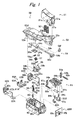
- a trigger switch 50 is provided with an operation part 51 capable of operation by a manual grasp, an actuator 61 operating together with the operation part, a plunger 54 for transmitting a condition of an operation of the operation part 51 to the actuator 61, a reverse member 58 for moving the actuator 61 straight in a direction same as that of rotation and a case 69 formed from an insulating member into a box-like shape having an opening at its top.
- the operation part 51 contains two return springs 52 inside.
- a rear end part of the operation part 51 is pivoted at one end of a cover 53, which holds lower ends of the return springs 52.
- the other end (a front end side) of the cover 53 contains the plunger 54 and functions as a lid of the case 69.
- the reverse member 58 is reversed by means of a reverse spring 57 on the basis of a condition of an operation of the operation part 51.
- a guide plate 55 guides the reverse.
- At the both ends of the reverse spring 57 provided are two plates 56a and 56b.
- the actuator 61 includes a rack part 61 c, movable contact pieces 65a and 65b, movable contacts 64a and 64b, which are mounted respectively to the movable contact pieces 65a and 65b and which are four in number in total, pressure springs 66a and 66b for constantly urging the movable contact pieces 65a and 65b and auxiliary contact engaging parts 61d and 61e for interlocking with first and second auxiliary contacts 83A and 83B with the first and second auxiliary contacts 83A and 83B being urged by spring pressure of auxiliary springs 84a and 84b.
- a stopper member 59 for locking the actuator 61 under a condition that the movable contact pieces 65a and 65b are in contact housed are a stopper spring 60, first and second terminals 62A and 62B, which are electrically connected to an external part and having two fixed contacts 57A and 67B, a third terminal 68A having two fixed contacts 63A and 63B and a fourth terminal 68B having a fixed contact 90j electrically connected to an external part.
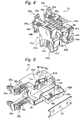
- Figs. 2 and 3 are vertical sectional side views of the trigger switch 50.
- the operation part 51 is a part operated by a hand of a user of the trigger switch 50. Pressing the operation part 51 causes the trigger switch 50 to be turned on while releasing the operation part 51 causes the trigger switch 50 to be turned off.
- the operation part 51 is formed from a top surface curved so as to suit to the shape of a hand, right and left side surfaces and a front surface, which are formed into one body with the top surface, and open rear and lower surfaces.
- the operation part 51 is formed into the shape of a hollow case as a whole.
- the right and left side surfaces of the operation part 51 are provided on their rear parts with two holes 51a.
- the holes 51a are engaged with protrusions 53a provided in the most rear parts of the both side surfaces of the cover 53 to connect the operation part 51 and the cover 53 (see Fig. 1 ).
- Two bearing holes 51 b are provided on the right and left side surfaces of the operation part 51.
- a later-mentioned rotation shaft 54e of the plunger 54 is rotatably fitted into the bearing holes 51b.
- through holes 51c which are in the shape of a gourd for the sake of convenience in use, are provided in the both side surfaces of the operation part 51 (see Fig. 1 ).
- the operation part 51 is provided inside the top plate thereof with two protrusions 51 d (see Fig. 2 ) for holding upper ends of the return springs 52.
- the two coiled return springs 52 are constantly urged in a direction of extension.
- the upper ends of the return springs 52 are fixed by means of the protrusions 51d (see Fig. 2 ) of the operation part 51.
- Lower ends of the return springs 52 are fixed by means of later-mentioned two protrusions 53b (see Fig. 2 ) provided on a bottom surface of the cover 53.
- the cover 53 has functions differen between a front half part and a rear half part, as shown in Figs. 1 to 3 .
- the rear half part has functions of holding the lower ends of the return springs 52 by means of the protrusions 53b and connecting to the rear end part of the operation part 51, as shown in Figs. 2 and 3 .
- the front half part of the cover 53 has a function as a lid of the case 69 to cover the plunger 54.
- An inclining part 53d provided at a most front part of the cover 53 forms a space inside which a pointed part 54d of the plunger 54 moves back and forth.
- the plunger 54 is comprised of, as shown in Figs. 1 to 3 , a rod part 54a, a rear block 54b fixed to a rear end of the rod part 54a, a rectangular stand-shaped member 54c fixed at a front end of the rod part 54a, the substantially triangular top end part 54d, which is formed at a front part of and into one body with the stand-shaped member 54c and which has a pointed top end, a first protrusion part 54g projecting downward at the rear part of the stand-shaped member 54c, a protrusion 55a (see Fig. 3 ) projecting downward from the center of a metal guide plate 55 mounted to a lower surface of the stand-shaped member 54c and a packing 54f.
- the rotation shaft 54e On right and left side surfaces of the rear block 54b, formed is the rotation shaft 54e (see Fig. 1 ).
- the rotation shaft 54e is fitted in the bearing holes 51 b of the operation part 51. Rotation movement of the operation part 51 is transmitted to the rear block 54b through the bearing holes 51 b.
- the rod part 54a transmits a movement of the rear block 54b in the back-and-forth direction to the stand-shaped member 54c.
- the top end part 54d is in the shape of a plate projecting from a center member in the right-and-left direction of the stand-shaped member 54c, the plate having the side surfaces in a substantially acute-angled triangle-shape.
- An outline of a top surface of the top end part 54d in a side view is arranged to accord with an inner surface of the inclining part 53d of the cover 53.
- a lower surface of the top end part 54d includes two horizontal surfaces having a difference in level and an inclining surface connecting the two horizontal surfaces.
- the top end part 54d is formed from a first horizontal surface extending from the top end to a center part, a first straight inclining surface extending downward from an end of the first horizontal surface, a second horizontal surface connected from an end of the first inclining surface and a second inclining surface getting narrow upward from an end of the second horizontal surface to the stand-shaped member 54c.
- the lower surface of the top end part 54d which is in the above shape, is constantly in contact with a top end (an inclining surface 59b) of a later-mentioned stopper member 59. This allows a function of controlling vertical movement of the stopper member 59 to be achieved simultaneously with achievement of a close relation with timing of turning on/off a contact.
- the protrusion 55a engaged with the guide plate 55 is engaged with the plate 56a to be connected with an upper end of the reverse spring 57.
- the packing 54f has a center hole for the rod part 54a passing therethrough and is fitted into a connection surface between the cover 53 and the case 69 to prevent dust caused by the plunger 54 moving in the back-and-forth direction from entering the inside of the switch.
- the guide plate 55 is a rectangular plate to be fitted between teeth in a lower surface of the stand-shaped member 54c of the plunger 54.
- a top end of the protrusion 55a (see Fig. 3 ) provided at the center of the guide plate 55 is engaged with the plate 56a.
- the upper plate 56a of the two disc-shaped plates 56a and 56b has a concave having a diameter larger a little than that of the protrusion 55a (see Fig. 3 ) at its center.
- the plate 56a is arranged to be capable of inclining freely like a spinning top when the top end of the protrusion 55a is in contact with the concave. Movement of the plunger 54 in the back-and-forth direction is transmitted from the protrusion 55a to the upper end of the reverse spring 57 through the plate 56a.
- the lower plate 56b of the two disc-shaped plates 56a and 56b has a concave at its center, the concave having a diameter larger a little than that of a protrusion provided in the reverse member 58.
- the plate 56b is arranged to be capable of inclining freely like a spinning top when a circular top end of the protrusion of the reverse member 58 is in contact with the concave.
- the coiled reverse spring 57 is held between the two plates 56a and 56b with predetermined pressure.
- the reverse spring 57 is bent in the back-and-forth direction to accumulate spring force when the plate 56a is moved by means of the plunger 54. A state that the spring force is most accumulated is called a reverse point.
- the reverse member 58 is comprised of a curved plate 58a formed from a rectangular plate shorter in length than the inner width of the cover 53 in the left-and-right direction, the rectangular plate being curved in the longitudinal and right-angled direction into the shape of an arc, two right and left partition plates 58b erected on an inner surface of the curved plate 58a with a space larger a little than the diameter of the plate 56b, a long and narrow pinion 58c provided along a lower surface of the curved plate 58a at its center part and protrusions 58d provided at respective upper end parts of the two partition plate 58b.
- the two partition plates 58b are for containing the reverse spring 57.
- the pinion 58c is engaged with the rack part 61c of the actuator 61, which will be mentioned later. This allows a function of converting rotation of the reverse member 58 into straight movement of the actuator 61 in the back-and-forth direction to be achieved.
- the protrusions 58d are engaged with two holes provided inside the upper surface of the cover 53, and thereby, form a rotation center of the reverse member 58.
- the reverse member 58 constantly receives pressure by means of the reverse spring 57.
- the pressure is the largest at the reverse point of the reverse spring 57.
- the stopper member 59 is formed into the shape of L as a whole.
- a vertical part of the stopper member 59 is fitted into a vertical groove provided at the center in the right-and-left direction of the case 69 in the most front part so as to be freely slidable.
- the inclining surface 59b extending downward to the rear side is formed in an upper end surface of the vertical part. The upper end surface is in contact with the lower surface of the top end part 54d of the plunger 54.
- a horizontal part of the stopper member 59 projects rearward in parallel to the bottom surface of the case 69.
- a claw part 59a in a top surface of a top end part of the horizontal part, formed into one body is a claw part 59a having an inclination extending downward from the front side to the rear side.
- the claw part 59a is to be engaged with a lock part 85 (see Figs. 5 and 14 ) of the actuator 61.
- the stopper spring 60 is housed in a hole provided in a lower part of the vertical part of the stopper member 59 and has a function to constantly urge the stopper member 59 upward. Accordingly, the stopper member 59 performs vertical movement in accordance with the shape of the lower surface of the top end part 54d when plunger 54 moves back and forth.
- the stopper member 59 is pressed down against the stopper spring 60 when the upper end of the vertical part of the stopper member 59 is in contact with the second horizontal surface, which is the lower surface, of the top end part 54d of the plunger 54, as shown in Fig. 2 , for example.
- extension force of the stopper spring 60 makes the top end of the vertical part rise along the first inclining surface.
- the stopper member 59 is kept at an upper part while the top end of the vertical part is in contact with the first horizontal surface of the top end part 54d.
- Each length of the horizontal surface and the inclining surface of the lower surface of the top end part 54d is designed, taking account of time of engagement between the claws part 59a of the stopper member 59 and the lock part 85 of the actuator 61, namely, timing of separation of the contacts in turning off the switch.
- the actuator 61 is comprised of, as shown in Figs. 1 , 4 and 5 , the rack part 61c formed from a rack 88 arranged in the horizontal direction so as to engage with the pinion 58c of the reverse member 58; the two box-shaped guide parts 61 a and 61 b formed into one body on the right and left sides of the rack part 61c, the movable contact pieces 65a and 65b mounted to respective front ends of the two guide parts 61a and 61 b, the movable contacts 64a and 64b, which are mounted to upper and lower parts of front surfaces of the movable contact pieces 65a and 65b and which are two each for right and left sides, namely, four in number in total, the pressure springs 66a and 66b contained in the box-shaped guide parts 61a and 61b for pressuring the movable contact pieces 65a and 65b from the rear side, and the auxiliary contact engaging parts 61d and 61e for engaged with the first and second auxiliary contacts 83A.
- Top end engaging parts 89a and 89b are top end parts constantly urged with urging force of the pressure springs 66a and 66b and hold the movable contact pieces 65a and 65b of the guide parts 61a and 61b.
- the top end engaging parts 89a and 89b have a function as a stopper when the movable contacts 64a and 64b of the movable contact pieces 65a and 65b come into contact with the fixed contacts 63A, (63B,) and 67A (and 67B) (see Fig. 18 ) and are further pushed to strengthen the urging force of the pressure springs 66a and 66b.
- the lock part 85 On a bottom surface of the rack part 61c, provided is the lock part 85 (see Fig. 5 ), which is to lock in the claw part 59a of the stopper member 59 and which is formed from a convex part having an inclining part on one side.
- An engaging convex part 86 is provided at an end opposite to the lock part 85 on the same bottom surface.
- a slider 87 which is formed from another member, is arranged to be mounted to the bottom surface between the lock part 85 and the engaging convex part 86.
- the first auxiliary contact 83A is formed from a conductive member into the shape of substantial C.
- An outer surface at a center position of the C-shaped part functions as a contact piece 83c.
- One end of the C-shaped part is engaged with the auxiliary contact engaging part 61 d to be locked.
- the auxiliary spring 84a is engaged with an inner surface of the locked first auxiliary contact 83A.
- the first auxiliary contact 83A is thus arranged to be one-sidedly engaged with the auxiliary contact engaging part 61d.
- the second auxiliary contact 83B is formed from a conductive member one size larger than the first auxiliary contact 83A into the shape of substantial C.
- An outer surface at a center position of the C-shaped part functions as a contact piece 83d.
- One end of the C-shaped part is engaged with the auxiliary contact engaging part 61e to be locked.
- the auxiliary spring 84b is engaged with an inner surface of the locked second auxiliary contact 83B.
- the second auxiliary contact 83B is thus arranged to be one-sidedly engaged with the auxiliary contact engaging part 61 e.
- a side surface on a free end side in the one-sided state is provided with a movable contact 83e.
- the movable contact 83e functions as a so-called brake contact. It is arranged that the movable contact 83e comes into contact with the fixed contact 90j of the fourth terminal 68B to short-circuit a motor not shown so as to put on a brake when the movable contact 83e is not drawn by the operation part. This will be described later.
- the actuator 61 having the above structure is driven by the reverse member 58 on the actuator guide laid in the case 69 in the back-and-forth direction to horizontally move in the back-and-forth direction with the movable contacts 64a and 64b.
- a slide of the first and second auxiliary contacts 83A and 83B, which form an auxiliary contact mechanism, in accordance with movement of the contacts allows auxiliary contact slide plate parts 81A and 82A, and 81 B and 82B to be electrically connected. This will be also described later.
- the first terminal 62A is comprised of an external connection terminal part 90b having a screw hole 80a at a center part of a flat plate formed from a conductive plate member, one end side of the conductive plate member being erected, as shown in Fig. 6 .
- the external connection terminal part 90b is bent at right angles to form a base part 90c.
- a left end part of the base part 90c is further bent at right angles to form an engaging plate part 90d.
- a surface connected from the engaging plate part 90d is bent at right angles to form a contact part 90e having the fixed contact 67A.
- An end side connected from the engaging plate part 90d is bent at right angles in a direction same as that of the base part 90c to form the auxiliary contact slide plate part 82A.
- the second terminal 62B is in the shape symmetrical to that of the first terminal 62A.
- the second terminal 62B is comprised of an external connection terminal part 90b having a screw hole 80b at a center part of a flat plate formed from a conductive plate member, one end side of the conductive plate member being erected.
- the external connection terminal part 90b is bent at right angles to form a base part 90c.
- a right end part of the base part 90c is further bent at right angles to form an engaging plate part 90d.
- a surface connected from the engaging plate part 90d is bent at right angles to form a contact part 90e having the fixed contact 67B.
- An end side connected from the engaging plate part 90d is bent at right angles in a direction same as that of the base part 90c to form the auxiliary contact slide plate part 82B.
- the third terminal 68A is formed from a conductive plate member into the shape of a fork.
- a top end side of one flat plate part 90g of the fork is bent at right angles to form a contact part 90e having the fixed contact 63A.
- a top end side of the other flat plate part 90h is bent at right angles to form a contact part 90f having the fixed contact 63B.
- the auxiliary contact slide plate part 81A is provided on a base part side connected from the flat plate part 90g.
- the auxiliary contact slide plate part 81 B formed wider than the auxiliary contact slide plate part 81A is provided connectedly from the flat plate part 90h and the auxiliary contact slide plate part 81A. Free end parts of the auxiliary contact slide plate parts 81A and 81B are beveled and worked so that the auxiliary contacts would be smoothly slidable.
- the fourth terminal 68B is formed from a conductive plate member into a substantially quadrilateral shape.
- a notch is formed at the center of a bottom part of the quadrilateral. It is arranged in the drawing with the notch that the fixed contact 90j be provided on a right side of the flat plate while the screw hole 80c be provided on a left side of the flat plate.
- the case 69 arranged and fixed are the first to fourth terminals 62A, 62B, 68A and 68B including the above-mentioned fixed contacts 63A, 63B, 67A and 67B, as shown in Fig. 6 .
- the case 69 further contains the actuator 61 including the movable contacts 64a and 64b to move the actuator 61 straight.
- the case 69 is formed from insulating resin into the shape of a box having an opening at an upper part thereof. Inside the case 69, formed are four compartments capable of containing the first to four terminals 62A, 62B, 68A and 68B.
- the case 69 is comprised of a support wall 91 a for externally providing the external connection terminal part 90b of the first terminal 62A.
- a first compartment 94 is formed in a space held among a longitudinal inner wall 92a, the support wall 91a, a stopper guide 93b for engaging with the stopper member 59 formed projectingly from the center to the inner side, and an actuator guide 93a forming a linear convex part provided at the center in a position extended from the stopper guide 93b.
- a second compartment 95 is formed in a space held among the similarly longitudinal inner wall 92b, a support wall 91 b and the actuator guide 93a
- a third compartment 96 is formed in a space held between the actuator guide 93a and the inner wall 92a at a position faced to the first compartment 94 with the external connection terminal part 90b of the first terminal 62A being faced to the outside.
- a fourth compartment 97 is formed in a space held between the actuator guide 93a and the inner wall 92b at a position faced to the second compartment 95 with the external connection terminal part 90b of the second terminal 62B being face to the outside.
- the third terminal 68A is first contained in the third and fourth compartments 96 and 97 as shown in Fig. 7 in order to engage and fix the first to fourth terminals 62A, 62B, 68A and 68B with and to the case 69 having such a structure. That is to say, the stopper guide 93b is put in a notched groove of the third terminal 68A to be pushed to the bottom so that the fixed contacts 63A and 63B would be arranged horizontally to the compartments and the auxiliary contact slide plate parts 31A and 81B would be arranged vertically to the compartments.
- the first terminal 62A is then contained in the first and third compartments 94 and 96 as shown in Fig. 8 . That is to say, the external connection terminal part 90b of the first terminal 62A is engaged with a slit of the support wall 91 a and the engaging plate part 90d is engaged with a slit of the inner wall 92a to be pushed. This allows the first terminal 62A to be arranged so that the fixed contact 67A would be faced inward horizontal to the compartments.
- the auxiliary contact slide plate part 82A is arranged in the bottom part of the third compartment 96 so as to be vertical to the compartment.
- the second terminal 62B is contained in the second and fourth compartments 95 and 97. That is to say, the external connection terminal part 90b of the second terminal 62B is engaged with a slit of the support wall 91b and the engaging plate part 90d is engaged with a slit of the inner wall 92b to be pushed. This allows the second terminal 62B to be arranged so that the fixed contact 67B would be faced inward horizontally to the compartments.
- the auxiliary contact slide plate part 82B is arranged in the bottom part of the fourth compartment 97 so as to be vertical to the compartment.
- the fourth terminal 68B is contained in the third and fourth compartments 96 and 97, as shown in Fig. 8 . That is to say, the plate-shaped fourth terminal 688 is engaged with a slit provided in a sidewall surface of the case to be pushed. This allows the fourth terminal 68B to be arranged and fixed so that the fixed contact 90j would be faced inward.
- Containing and fixing the four first to fourth terminals 62A, E2B, 68A and 68B in and to the case 69 as described above allows the fixed contacts 63A, 63B, 67A and 67B to be faced in the same direction and the auxiliary contact slide plate parts 81A, 81 B, 82A and 82B in which the auxiliary contacts slide to be arranged in a bottom surface of the case 69, so that the fixed contact 90j is arranged so as to be faced to the fixed contact 63B.
- the movable contacts to be arranged to face to the fixed contacts and the auxiliary contacts to be arranged to be in contact with upper parts of the auxiliary contact slide plate parts. Accordingly, the movable contacts of the actuator are arranged to be in contact with the fixed contact 90j of the fourth terminal 68B.
- Each of the screw hole 80a of the first terminal 62A, the screw hole 80b of the second terminal 62B and the screw hole 80c of the fourth terminal 68B is connected to the motor M and a power source AC via an electric wire as shown by a dotted line in Fig. 8 .
- the movable contacts 64a and 64b come into contact with the fixed contacts 63A and 87A, and 63B and 678 by means of a contact mechanism of a switch, which is achieved by coordinated movements of the plunger 54, the reverse member 58, the actuator 61 and such, so as to be slowly turned on and fast turned off.
- the auxiliary movable contact comes into contact with the auxiliary fixed contact only when the movable contact is in contact with the fixed contact.
- the auxiliary movable contact does not come into contact with the auxiliary fixed contact in the case that the movable contact is not in contact with the fixed contact.
- circuit diagram shown in Fig. 9 shown as a circuit diagram is a contact state of the auxiliary contact in addition to contact states of the fixed contacts and the movable contacts.
- the circuit diagram is characterized by providing main contacts connected double in series and a brake contact for the auxiliary contact.
- the main contacts double in series correspond to the fixed contact 67A of the first terminal 62A and the fixed contact 63Aofthe third terminal 68A for the movable contacts 64a and 64b of the movable contact piece 65a of the actuator 61 and the fixed contact 67B of the second terminal 68A and the fixed contact 63B of the third terminal 68A for the movable contacts 64a and 64b of the movable contact piece 65b of the actuator 61 while the single brake contact corresponds to the movable contact 83e of the second auxiliary contact 83B sliding on the second terminal 62B for the fixed contact 90j of the fourth terminal 68B.
- the movable contact 83e of the second auxiliary contact 83B comes into contact with the fixed contact 90j of the fourth terminal 68B to short-circuit the motor M, and thereby, to keep a brake being put on when the operation part is not operated.
- Drawing the operation part causes the actuator to move and the first auxiliary contact 83A and the second auxiliary contact 83B to slide.
- a slide of the second auxiliary contact 83B causes the movable contact 83e to separate from the fixed contact 90j, which is in contact with the movable contact 83e, so that a short circuit of the motor M is released.
- the operation part after the above causes the movable contacts 64a and 64b of the movable contact piece 65a to come into contact with the fixed contact 67A of the first terminal 62A and the fixed contact 63A of the third terminal 68A and causes the movable contacts 64a and 64b of the movable contact piece 65b to come into contact with the fixed contact 638 of the third terminal 68A and the fixed contact 67B of the second terminal 62B, as shown in Fig. 10 .
- the first auxiliary contact 83A and the second auxiliary contact 83B which are the auxiliary contacts, slide to middle parts of the auxiliary contact slide plate parts 82A and 82B and do not reach the auxiliary contact slide plate parts 81A and 81 B. That is to say, at that time, contact of the contacts causes the main contacts double in series to turn on to supply the motor M with power, and thereby, the motor M is made rotatable.
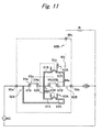
- the operation part following to the above causes the main contacts double in series to be in contact under the increased urging force of the spring, as shown in Fig. 11 , and then, the state is locked although this is not shown.
- the first and second auxiliary contacts 83A and 83B bridge over the auxiliary contact slide plate parts (81 A and 82A, and 81 B and 82B), so that conduction is achieved.
- the opening of a path for supplying the motor with power from the auxiliary sides allows the unstable contact between the fixed contacts and the movable contacts to be compensated on the auxiliary contact sides, so that stable conduction can be achieved as a whole.
- stopping drawing of the operation part under the above condition causes the fixed contacts and the movable contacts to be changed in state from on to off and the conduction at the auxiliary contact not to be achieved.
- the movable contact 83e of the second auxiliary contact 83B finally comes into contact with the fixed contact 90j to short-circuit the motor M, and thereby, to put on a brake.
- the plunger 54 is urged in a direction of an arrow A by means of spring force of the return spring 52 in the case of an off state under which the switch is not operated.
- the pointed part 54d of the plunger 54 is pressed against an inner wall of the cover 53, and therefore, not movable.
- the reverse member 58 is pressured by the reverse spring 57 to be urged counterclockwise under such a condition. Accordingly the actuator 61 on the actuator guide 93 is urged to a direction B but cannot move.
- the first auxiliary contact 83A is stopped in contact with the auxiliary contact slide plate part 82A of the first terminal 62A at that time.
- the second auxiliary contact 83B is also stopped in contact with the auxiliary contact slide plate part 82B of the second terminal 62B, similarly, as a part of the above is shown in Fig. 12 .
- the movable contact 83e provided in the second auxiliary contact 83B is simultaneously in contact with the fixed contact 90j provided in the fourth terminal 68B to achieve an electrically connected state.
- Extension force of the reverse spring 57 makes the reverse member 58 strongly rotate in a direction of an arrow E at the reverse point of the reverse spring 57.
- the rack 88 of the rack part 61c engaged with the pinion 58c of the reverse member 58 moves horizontally in the direction of the arrow E.
- the first auxiliary contact 83A is still in contact with the auxiliary contact slide plate part 82A of the first terminal 62A and a partition part of the case 69 at that time.
- the movable contact 83e provided in the second auxiliary contact 83B simultaneously separates from the fixed contact 90j provided in the fourth terminal 68B.
- the lock part 85 of the actuator 61 is located on the claw part 59a of the stopper member 59. Accordingly, the contact state between the fixed contacts 67A and 63A and the movable contacts 64a and 64b is not locked since it is based on a condition of a pushing operation of the operation part 51. Moreover, the urging force of the pressure spring 66a for the movable contacts 64a and 64b is constant urging force.
- pushing the operation part 51 causes the actuator 61 to further move horizontally with the fixed contacts 87A and 63A being in contact with the movable contacts 64a and 64b, so that the pressure spring 66a is compressed to further strengthen contact pressure between the fixed contacts 67A and 63A and the movable contacts 64a and 64b, as shown in Fig. 14 .
- the first auxiliary contact 83A comes to bridge over the auxiliary contact slide plate part 82A of the first terminal 62A and the auxiliary contact slide plate part 81A of the third terminal 68A to achieve contact therebetween.
- the second auxiliary contact 83B not shown comes to bridge over the auxiliary contact slide plate part 82B of the second terminal 62B and the auxiliary contact slide plate part 81 B of the third terminal 68A to achieve contact therebetween.
- the fixed contacts 67A and 63A are in contact with the movable contacts 64a and 64b at that time. Accordingly, there is no potential between the auxiliary contact slide plate parts 81A and 82A. This causes no arc in the auxiliary contacts, and therefore, no roughness of the contacts to occur.
- the auxiliary contact slide plate part 82A is made contact with the auxiliary contact slide plate part 81A by means of the first auxiliary contact 83A (similarly, the auxiliary contact slide plate part 82B is made contact with the auxiliary contact slide plate part 81 B by means of the second auxiliary contact 83B not shown), and thereby, the lock part 85 is fitted into the claw part 59C to lock horizontal movement of the actuator 61 in a pressing direction, as shown in Fig. 15 .
- This allows contact between the fixed contacts and the movable contacts to be maintained with urging force of the pressure spring 66a being kept constant and locked.
- the actuator 61 moves horizontally to move the claw part 59C and the lock part 85 a little, as shown in Fig. 16 .
- the lock state is kept, the contact state between the fixed contacts 67A and 63A and the movable contacts 64a and 64b is maintained, and the contact state between the first auxiliary contact 83A and the second auxiliary contact 83B is also held maintained.
- Maintaining an on state of the operation part 51 as described above allows a locked state of the fixed contacts 87A and 63A and the movable contacts 64a and 64b to be maintained and an electric contact state to be maintained under a condition that the first auxiliary contact 83A bridges over the auxiliary contact slide plate parts 81A and 82A (similarly, a condition that the second auxiliary contact 83B bridges over the auxiliary contact slide plate parts 81 B and 82B).
- the first auxiliary contact 83A moves from the electrically contacting state achieved by bridging over the slide plate parts 81A and 82A to the state of no contact in accordance with movement of the actuator 61 before the movable contacts 64a and 64b separate from the fixed contacts 67A and 63A. Accordingly, no potential between the auxiliary contact slide plate parts 81A and 82A causes an arc in the first auxiliary contact 83A to occur, so that no roughness of the contacts also occurs.
- the second auxiliary contact 83B also moves from the electrically contacting state achieved by bridging over the slide plate parts 81B and 82B to the state of no contact in accordance with movement of the actuator 61. Accordingly, no potential between the auxiliary contact slide plate parts 818 and 82B causes an arc in the second auxiliary contact 83B to occur.
- the operation part 51 is operated to make the fixed contacts 67A and 63A contact with the movable contacts 64a and 64b and make the first auxiliary contact 83A contact with the second auxiliary contact 83B.
- the connection mechanism of the switch other than addition of the auxiliary movable contact 83e to the second auxiliary contact 83B is same as the connection mechanism described in the related art.
- Fig. 17 shows an electric tool comprising the trigger switch 50 in accordance with the invention of the application.
- the trigger switch 50 is housed at a position held by a hand.
- the AC voltage is supplied from the outside. Operating the trigger switch 50 allows the motor M to rotate and rotation to be achieved through a transmission gear G.
- the invention is useful as a trigger switch mounted to an electric tool, the trigger switch comprising a contact mechanism of a spring reverse type switch suitable for large AC and DC.
Landscapes
- Push-Button Switches (AREA)
- Portable Power Tools In General (AREA)
- Rotary Switch, Piano Key Switch, And Lever Switch (AREA)
Claims (7)
- Kippschalter, der aufweist:ein Paar fester Kontakte (63A, 67A, 63B, 67B), die einen in Reihe geschalteten Hauptdoppelkontakt bilden und als ein Schalter zur Versorgung eines Motors (M) mit Strom dienen, und Schieberplattenteile (81A, 82A, 81B, 82B), die mit den festen Kontakten verbunden sind; undein Paar beweglicher Kontakte (64a, 64b), die in einem Betätigungselement (61) vorgesehen sind, das mit einem Bedienungsteil (51) ineinandergreift, und mit dem Paar der festen Kontakte in Kontakt kommt und/oder sich von ihnen entfernt,wobei das Betätigungselement (61) ein Paar Hilfskontakte (83A, 83B) aufweist, die auf den Schieberplattenteilen gleiten, wobeidie festen Kontakte (63A, 67A, 63B, 67B), die beweglichen Kontakte (64a, 64b) und die Hilfskontakte (83A, 83B) derart angeordnet sind, dass:Ziehen am Bedienungsteil (51) bewirkt, dass sich das Betätigungselement (61) in eine Vorwärtsrichtung bewegt, um die beweglichen Kontakte mit den festen Kontakten in elektrischen Kontakt zu bringen, um den Motor mit Strom zu versorgen, während die Hilfskontakte dazu gebracht werden, die Schieberplattenteile nur dann zu überbrücken, wenn sich die beweglichen Kontakte in Kontakt mit den festen Kontakten befinden, um einen elektrischen Kontakt zu erzielen, um kein Potential im Kontakt zwischen den Hilfskontakten und den Schieberplattenteilen zu erzeugen, undLoslassen des Bedienungsteils bewirkt, dass sich das Betätigungselement in eine umgekehrte Richtung bewegt, um die beweglichen Kontakte von den festen Kontakten zu trennen, nachdem die Durchführung der Bewegung der Hilfskontakte, die die Schieberplattenteile überbrücken, eine Unterbrechung des Kontakts mit dem Schieberplattenteil bewirkt, und ein beweglicher Kontakt (83e), der im Hilfskontakt (83B) vorgesehen ist, zum Kurzschließen des Motors in Kontakt mit einem festen Kontakt (90j) steht.
- Kippschalter nach Anspruch 1, wobei der Kippschalter ein Rückstellfederschalter ist, der aufweist:das Paar der festen Kontakte (63A, 67A und 63B, 67B), die so angeordnet sind, dass sie in einem kastenförmigen Gehäuse (69) mit einer Öffnungsfläche in eine selbe Richtung weisen;das Betätigungselement (61), das Druckfedern (66a, 66b) zum Drücken auf das Paar beweglicher Kontakte von einer Rückseite aufweist;ein drehbares Rückstellelement (58) zum Antreiben des Betätigungselements (61);eine Spiralrückstellfeder (57), deren eines Ende mit dem Rückstellelement verbunden ist und deren anderes Ende mit einem Stößel (54) in Eingriff steht, wobei die Rückstellfeder (57) einen Umkehrpunkt aufweist; unddas Bedienungsteil (51) zum Bewegen des Stößels (54),wodurch das Bedienungsteil (51) gedrückt/gelöst wird, um das Paar beweglicher Kontakte (64a, 64b) in Kontakt mit dem Paar der festen Kontakte (63A, 67A und 63B, 67B) zu bringen/von ihm zu entfernen, um den in Reihe geschalteten Hauptdoppelkontakt ein-/auszuschalten,wobei ein Schieberplattenteil (81A oder 81B) aus den Schieberplattenteilen (81A, 82A, 81B, 82B), das mit einem festen Kontakt des Paars der festen Kontakte (63A, 67A und 63B, 67B) verbunden ist, und ein Schieberplattenteil (82A oder 82B) aus den Schieberplattenteilen, das mit dem anderen festen Kontakt verbunden ist, vorgesehen sind, unddie festen Kontakte (63A, 67A, 63B, 67B), die beweglichen Kontakte (64a, 64b) und die Hilfskontakte (83A, 83B) derart angeordnet sind, dass:eine Umkehrbewegung des Rückstellelements (58) bewirkt, dass das Paar der beweglichen Kontakte (64a, 64b) mit dem Paar der festen Kontakte (63A, 67A und 63B, 67B) in Kontakt kommt, und bewirkt, dass das Paar der Hilfskontakte (83A, 83B) das Schieberplattenteil, das mit einem festen Kontakt des Paars der festen Kontakte verbunden ist, und das Schieberplattenteil überbrückt, das mit dem anderen festen Kontakt verbunden ist, um einen elektrischen Kontakt zu erzielen, nachdem sich das Betätigungselement (61) um einen festen Betrag bewegt hat, um einen Abstand zwischen den Kontakten vor dem Umkehrpunkt beim Einschalten des in Reihe geschalteten Hauptdoppelkontakts zu reduzieren, unddas Lösen der Hemmung des Betätigungselements (61) nach dem Umkehrpunkt bewirkt, dass sich das Paar der beweglichen Kontakte (64a, 64b) vom Paar der festen Kontakte (63A, 67A und 63B, 67B) entfernt, und bewirkt, dass der elektrische Kontakt gelöst wird, der durch das Paar der Hilfskontakte (83A, 83B) erzielt wird, die das Schieberplattenteil, das mit einem festen Kontakt des Paars der festen Kontakte verbunden ist, und das Schieberplattenteil überbrücken, das mit dem anderen festen Kontakt verbunden ist, und bewirkt, dass der Motor kurzgeschlossen wird, indem der im Schieberplattenteil vorgesehene bewegliche Kontakt (83e) mit dem festen Kontakt (90j) in Kontakt gebracht wird, der auf einer gegenüberliegenden Seite so vorgesehen ist, dass er zum Paar der festen Kontakte weist, um nach der Bewegungshemmung des Betätigungselements vor dem Umkehrpunkt beim Ausschalten des in Reihe geschalteten Hauptdoppelkontakts einen elektrischen Kontakt zu erzielen.
- Kippschalter nach Anspruch 2, wobei im Rückstellelement (58) ein Ritzel (58c) ausgebildet ist und im Betätigungselement (61) eine mit dem Ritzel in Eingriff stehende Zahnstange (61c) ausgebildet ist.
- Kippschalter nach Anspruch 2 oder 3, wobei der Stößel (54) ein Erhebungsteil aufweist, das nach unten vorsteht, das Rückstellelement (58) einen Vorsprung aufweist, der durch das Erhebungsteil entsprechend eines Drucks des Bedienungsteils (51) unter Druck gesetzt wird, und ein Herunterdrücken des Bedienungsteils bewirkt, dass das Erhebungsteil den Vorsprung des Rückstellelements unter Druck setzt, um das Rückstellelement gegen die Kraft der Rückstellfeder (57) rotieren zu lassen, und bewirkt, dass sich das Betätigungselement (61) bewegt, so dass sich der bewegliche Kontakt dem festen Kontakt nähert.
- Kippschalter nach Anspruch 2, 3 oder 4, wobei an einer Unterseite des Stößels (54) an seinem oberen Endteil eine Oberfläche mit einem geringen Höhenunterschied ausgebildet ist, ein Anschlagelement (59) vorgesehen ist, das ein Klauenteil (59a) aufweist und die Oberfläche mit einem Höhenunterschied konstant berührt, eine Anschlagfeder (60) vorgesehen ist, um das Anschlagelement (59) nach oben zu drücken, das Betätigungselement (61) zum Eingriff mit dem Klauenteil (59a) des Anschlagelements mit einem Arretierungsteil (85) versehen ist, und eine Bewegung des Anschlagelements (59) längs der Oberfläche mit einem Höhenunterschied des Stößels (54) den Eingriff des Klauenteils des Anschlagelements mit dem Vorsprung des Betätigungselements (61) arretiert oder löst.
- Kippschalter nach Anspruch 5, wobei das Anschlagelement (59) beim Einschalten des Schalters angehoben wird, sich das Arretierungsteil (85) des Betätigungselements (61) über das Klauenteil (59a) des Anschlagelements bewegt, so dass der bewegliche Kontakt mit dem festen Kontakt in Kontakt kommt, und der Eingriff des Klauenteils mit dem Arretierungsteil des Betätigungselements zu der Zeit arretiert wird.
- Kippschalter nach Anspruch 2, 3, 4, 5 oder 6, wobei die Bewegung des Bedienungsteils in eine Ausschaltrichtung, um den Stößel (54) über den Umkehrpunkt der Rückstellfeder (57) in den arretierten Zustand zu bewegen, infolge der Form der Unterseite des Stößels am oberen Endteil für eine Zeitspanne keinen Freigabezustand bewirkt, eine weitere Bewegung des Bedienungsteils in eine Ausschaltrichtung über den Umkehrpunkt der Rückstellfeder bewirkt, dass sich das Anschlagelement (59) infolge der Unterseite des Stößels am oberen Endteil nach unten bewegt, um die Arretierungseinrichtung zu lösen, und sich als Ergebnis das Betätigungselement (61) unmittelbar bewegt und der bewegliche Kontakt sofort vom festen Kontakt getrennt wird, um auszuschalten.
Applications Claiming Priority (1)
| Application Number | Priority Date | Filing Date | Title |
|---|---|---|---|
| JP2007310374A JP5028236B2 (ja) | 2007-11-30 | 2007-11-30 | トリガースイッチ |
Publications (3)
| Publication Number | Publication Date |
|---|---|
| EP2065909A2 EP2065909A2 (de) | 2009-06-03 |
| EP2065909A3 EP2065909A3 (de) | 2011-07-06 |
| EP2065909B1 true EP2065909B1 (de) | 2012-09-05 |
Family
ID=40351903
Family Applications (1)
| Application Number | Title | Priority Date | Filing Date |
|---|---|---|---|
| EP08170181A Not-in-force EP2065909B1 (de) | 2007-11-30 | 2008-11-28 | Kippschalter |
Country Status (4)
| Country | Link |
|---|---|
| US (1) | US7982152B2 (de) |
| EP (1) | EP2065909B1 (de) |
| JP (1) | JP5028236B2 (de) |
| CN (1) | CN101447344B (de) |
Families Citing this family (7)
| Publication number | Priority date | Publication date | Assignee | Title |
|---|---|---|---|---|
| JP5409227B2 (ja) * | 2009-09-15 | 2014-02-05 | 佐鳥エス・テック株式会社 | トリガースイッチ |
| CN102983033B (zh) * | 2012-11-15 | 2015-06-10 | 科都电气有限公司 | 一种具有突跳机构的扳动开关 |
| JP5773001B2 (ja) * | 2014-02-14 | 2015-09-02 | オムロン株式会社 | 接点機構およびこれを用いたトリガースイッチ,電動工具 |
| CN104157487B (zh) * | 2014-07-29 | 2016-03-09 | 瑞安市华通器具开关有限公司 | 电动工具开关 |
| JP6530869B2 (ja) * | 2016-11-16 | 2019-06-12 | 東京コスモス電機株式会社 | 可変抵抗器用スイッチ装置 |
| EP3588525B1 (de) | 2018-06-28 | 2022-02-16 | Black & Decker Inc. | Elektronisches schaltmodul mit entgegengesetzt angeordneten leistungsschaltern und diskreten kühlkörpern |
| CN113561137B (zh) * | 2021-05-28 | 2022-11-29 | 莱克电气绿能科技(苏州)有限公司 | 一种工具机开关联动器及工具机 |
Family Cites Families (13)
| Publication number | Priority date | Publication date | Assignee | Title |
|---|---|---|---|---|
| US4206333A (en) * | 1978-08-17 | 1980-06-03 | Eaton Corporation | Double pole sliding contact trigger switch with sequential auxiliary butt contacts |
| US4282414A (en) * | 1979-08-30 | 1981-08-04 | Westinghouse Electric Corp. | Convertible switch operator |
| JPH06223674A (ja) * | 1993-01-27 | 1994-08-12 | Omron Corp | トリガースイッチ |
| JPH0714459A (ja) * | 1993-06-22 | 1995-01-17 | Alps Electric Co Ltd | 開閉器 |
| US5600107A (en) * | 1995-07-27 | 1997-02-04 | Eaton Corporation | Electric switch with dynamic brake contact shared for making and breaking a power circuit |
| JPH09320396A (ja) * | 1996-06-03 | 1997-12-12 | Omron Corp | トリガースイッチ |
| US5929407A (en) * | 1998-02-19 | 1999-07-27 | Eaton Corporation | Plunger actuated switch with single adjustment features |
| JP4063528B2 (ja) * | 2001-11-27 | 2008-03-19 | 佐鳥エス・テック株式会社 | スイッチの接触機構 |
| US6749028B1 (en) * | 2003-05-22 | 2004-06-15 | Defond Components Limited | Power tool trigger assembly |
| JP4354921B2 (ja) * | 2005-02-09 | 2009-10-28 | 佐鳥エス・テック株式会社 | トリガースイッチ回路及び電動工具並びにトリガースイッチ |
| CN100466127C (zh) * | 2005-04-18 | 2009-03-04 | 创科实业有限公司 | 开关组件 |
| US7705260B2 (en) * | 2005-04-18 | 2010-04-27 | Xinsheng Xu | Switch assembly |
| JP4611177B2 (ja) * | 2005-11-09 | 2011-01-12 | 佐鳥エス・テック株式会社 | トリガースイッチ |
-
2007
- 2007-11-30 JP JP2007310374A patent/JP5028236B2/ja not_active Expired - Fee Related
-
2008
- 2008-11-26 US US12/292,807 patent/US7982152B2/en not_active Expired - Fee Related
- 2008-11-28 EP EP08170181A patent/EP2065909B1/de not_active Not-in-force
- 2008-11-28 CN CN2008101797260A patent/CN101447344B/zh not_active Expired - Fee Related
Also Published As
| Publication number | Publication date |
|---|---|
| CN101447344B (zh) | 2012-06-20 |
| CN101447344A (zh) | 2009-06-03 |
| EP2065909A3 (de) | 2011-07-06 |
| JP2009135000A (ja) | 2009-06-18 |
| US20090139849A1 (en) | 2009-06-04 |
| JP5028236B2 (ja) | 2012-09-19 |
| EP2065909A2 (de) | 2009-06-03 |
| US7982152B2 (en) | 2011-07-19 |
Similar Documents
| Publication | Publication Date | Title |
|---|---|---|
| EP2065909A2 (de) | Kippschalter | |
| US4570078A (en) | Switch assembly for a motor vehicle | |
| US3755640A (en) | Reversing switch for a power tool with separate selectively movable contact carriers | |
| JP4279648B2 (ja) | スイッチ装置 | |
| JP2003141971A (ja) | スイッチ装置 | |
| CN101083178A (zh) | 滑动开关 | |
| JP6113038B2 (ja) | スイッチ | |
| JPH0132604B2 (de) | ||
| JP2018107088A (ja) | スイッチの接点構造、トリガースイッチ及び電動工具 | |
| JP4063528B2 (ja) | スイッチの接触機構 | |
| JP4122697B2 (ja) | スイッチ装置 | |
| US5378863A (en) | Electric switch | |
| JP4611177B2 (ja) | トリガースイッチ | |
| JP4523377B2 (ja) | 電動工具のスイッチ機構 | |
| JP2002150875A (ja) | スイッチ装置とこのスイッチ装置を用いたセーフティ装置 | |
| JP4114327B2 (ja) | 押釦スイッチ装置 | |
| JP2003308774A (ja) | プラグイン型回路遮断器 | |
| JPS6328817Y2 (de) | ||
| JP2842560B2 (ja) | 回路遮断器 | |
| JPH01246083A (ja) | 電動工具 | |
| JPH0334017Y2 (de) | ||
| JP2003208842A (ja) | 回路遮断器 | |
| JPS6335042B2 (de) | ||
| JP2001229781A (ja) | プッシュスライドスイッチ | |
| JPH08235968A (ja) | ピアノハンドル式両切りスイッチ |
Legal Events
| Date | Code | Title | Description |
|---|---|---|---|
| PUAI | Public reference made under article 153(3) epc to a published international application that has entered the european phase |
Free format text: ORIGINAL CODE: 0009012 |
|
| AK | Designated contracting states |
Kind code of ref document: A2 Designated state(s): AT BE BG CH CY CZ DE DK EE ES FI FR GB GR HR HU IE IS IT LI LT LU LV MC MT NL NO PL PT RO SE SI SK TR |
|
| AX | Request for extension of the european patent |
Extension state: AL BA MK RS |
|
| PUAL | Search report despatched |
Free format text: ORIGINAL CODE: 0009013 |
|
| AK | Designated contracting states |
Kind code of ref document: A3 Designated state(s): AT BE BG CH CY CZ DE DK EE ES FI FR GB GR HR HU IE IS IT LI LT LU LV MC MT NL NO PL PT RO SE SI SK TR |
|
| AX | Request for extension of the european patent |
Extension state: AL BA MK RS |
|
| 17P | Request for examination filed |
Effective date: 20111214 |
|
| GRAP | Despatch of communication of intention to grant a patent |
Free format text: ORIGINAL CODE: EPIDOSNIGR1 |
|
| AKX | Designation fees paid |
Designated state(s): DE GB |
|
| GRAS | Grant fee paid |
Free format text: ORIGINAL CODE: EPIDOSNIGR3 |
|
| GRAA | (expected) grant |
Free format text: ORIGINAL CODE: 0009210 |
|
| AK | Designated contracting states |
Kind code of ref document: B1 Designated state(s): DE GB |
|
| REG | Reference to a national code |
Ref country code: GB Ref legal event code: FG4D |
|
| REG | Reference to a national code |
Ref country code: DE Ref legal event code: R096 Ref document number: 602008018535 Country of ref document: DE Effective date: 20121031 |
|
| PGFP | Annual fee paid to national office [announced via postgrant information from national office to epo] |
Ref country code: GB Payment date: 20121130 Year of fee payment: 5 |
|
| PGFP | Annual fee paid to national office [announced via postgrant information from national office to epo] |
Ref country code: DE Payment date: 20121228 Year of fee payment: 5 |
|
| PLBE | No opposition filed within time limit |
Free format text: ORIGINAL CODE: 0009261 |
|
| STAA | Information on the status of an ep patent application or granted ep patent |
Free format text: STATUS: NO OPPOSITION FILED WITHIN TIME LIMIT |
|
| 26N | No opposition filed |
Effective date: 20130606 |
|
| REG | Reference to a national code |
Ref country code: DE Ref legal event code: R097 Ref document number: 602008018535 Country of ref document: DE Effective date: 20130606 |
|
| GBPC | Gb: european patent ceased through non-payment of renewal fee |
Effective date: 20131128 |
|
| PG25 | Lapsed in a contracting state [announced via postgrant information from national office to epo] |
Ref country code: DE Free format text: LAPSE BECAUSE OF NON-PAYMENT OF DUE FEES Effective date: 20140603 |
|
| REG | Reference to a national code |
Ref country code: DE Ref legal event code: R119 Ref document number: 602008018535 Country of ref document: DE Effective date: 20140603 |
|
| PG25 | Lapsed in a contracting state [announced via postgrant information from national office to epo] |
Ref country code: GB Free format text: LAPSE BECAUSE OF NON-PAYMENT OF DUE FEES Effective date: 20131128 |