EP2065984B1 - Connecteur à fiches électriques pour un passage de câbles pouvant être séparé - Google Patents
Connecteur à fiches électriques pour un passage de câbles pouvant être séparé Download PDFInfo
- Publication number
- EP2065984B1 EP2065984B1 EP08020418.3A EP08020418A EP2065984B1 EP 2065984 B1 EP2065984 B1 EP 2065984B1 EP 08020418 A EP08020418 A EP 08020418A EP 2065984 B1 EP2065984 B1 EP 2065984B1
- Authority
- EP
- European Patent Office
- Prior art keywords
- plug
- connector
- contact
- cable
- connection
- Prior art date
- Legal status (The legal status is an assumption and is not a legal conclusion. Google has not performed a legal analysis and makes no representation as to the accuracy of the status listed.)
- Ceased
Links
- 230000001681 protective effect Effects 0.000 claims description 3
- 229910000679 solder Inorganic materials 0.000 claims description 3
- 238000007789 sealing Methods 0.000 claims description 2
- 230000000295 complement effect Effects 0.000 claims 1
- 230000005405 multipole Effects 0.000 claims 1
- 230000007704 transition Effects 0.000 description 15
- 238000009434 installation Methods 0.000 description 6
- 239000000969 carrier Substances 0.000 description 1
- 239000004020 conductor Substances 0.000 description 1
- 238000011161 development Methods 0.000 description 1
- 230000018109 developmental process Effects 0.000 description 1
- 238000001125 extrusion Methods 0.000 description 1
- 238000003780 insertion Methods 0.000 description 1
- 230000037431 insertion Effects 0.000 description 1
- 238000012986 modification Methods 0.000 description 1
- 230000004048 modification Effects 0.000 description 1
- 238000012806 monitoring device Methods 0.000 description 1
- 238000012544 monitoring process Methods 0.000 description 1
- BASFCYQUMIYNBI-UHFFFAOYSA-N platinum Chemical compound [Pt] BASFCYQUMIYNBI-UHFFFAOYSA-N 0.000 description 1
- 238000005476 soldering Methods 0.000 description 1
- 238000004804 winding Methods 0.000 description 1
Images

Classifications
-
- H—ELECTRICITY
- H01—ELECTRIC ELEMENTS
- H01R—ELECTRICALLY-CONDUCTIVE CONNECTIONS; STRUCTURAL ASSOCIATIONS OF A PLURALITY OF MUTUALLY-INSULATED ELECTRICAL CONNECTING ELEMENTS; COUPLING DEVICES; CURRENT COLLECTORS
- H01R13/00—Details of coupling devices of the kinds covered by groups H01R12/70 or H01R24/00 - H01R33/00
- H01R13/46—Bases; Cases
- H01R13/516—Means for holding or embracing insulating body, e.g. casing, hoods
- H01R13/518—Means for holding or embracing insulating body, e.g. casing, hoods for holding or embracing several coupling parts, e.g. frames
-
- H—ELECTRICITY
- H01—ELECTRIC ELEMENTS
- H01R—ELECTRICALLY-CONDUCTIVE CONNECTIONS; STRUCTURAL ASSOCIATIONS OF A PLURALITY OF MUTUALLY-INSULATED ELECTRICAL CONNECTING ELEMENTS; COUPLING DEVICES; CURRENT COLLECTORS
- H01R25/00—Coupling parts adapted for simultaneous co-operation with two or more identical counterparts, e.g. for distributing energy to two or more circuits
-
- H—ELECTRICITY
- H01—ELECTRIC ELEMENTS
- H01R—ELECTRICALLY-CONDUCTIVE CONNECTIONS; STRUCTURAL ASSOCIATIONS OF A PLURALITY OF MUTUALLY-INSULATED ELECTRICAL CONNECTING ELEMENTS; COUPLING DEVICES; CURRENT COLLECTORS
- H01R27/00—Coupling parts adapted for co-operation with two or more dissimilar counterparts
- H01R27/02—Coupling parts adapted for co-operation with two or more dissimilar counterparts for simultaneous co-operation with two or more dissimilar counterparts
-
- H—ELECTRICITY
- H01—ELECTRIC ELEMENTS
- H01R—ELECTRICALLY-CONDUCTIVE CONNECTIONS; STRUCTURAL ASSOCIATIONS OF A PLURALITY OF MUTUALLY-INSULATED ELECTRICAL CONNECTING ELEMENTS; COUPLING DEVICES; CURRENT COLLECTORS
- H01R9/00—Structural associations of a plurality of mutually-insulated electrical connecting elements, e.g. terminal strips or terminal blocks; Terminals or binding posts mounted upon a base or in a case; Bases therefor
- H01R9/03—Connectors arranged to contact a plurality of the conductors of a multiconductor cable, e.g. tapping connections
-
- H—ELECTRICITY
- H01—ELECTRIC ELEMENTS
- H01R—ELECTRICALLY-CONDUCTIVE CONNECTIONS; STRUCTURAL ASSOCIATIONS OF A PLURALITY OF MUTUALLY-INSULATED ELECTRICAL CONNECTING ELEMENTS; COUPLING DEVICES; CURRENT COLLECTORS
- H01R12/00—Structural associations of a plurality of mutually-insulated electrical connecting elements, specially adapted for printed circuits, e.g. printed circuit boards [PCB], flat or ribbon cables, or like generally planar structures, e.g. terminal strips, terminal blocks; Coupling devices specially adapted for printed circuits, flat or ribbon cables, or like generally planar structures; Terminals specially adapted for contact with, or insertion into, printed circuits, flat or ribbon cables, or like generally planar structures
- H01R12/70—Coupling devices
- H01R12/71—Coupling devices for rigid printing circuits or like structures
- H01R12/72—Coupling devices for rigid printing circuits or like structures coupling with the edge of the rigid printed circuits or like structures
- H01R12/721—Coupling devices for rigid printing circuits or like structures coupling with the edge of the rigid printed circuits or like structures cooperating directly with the edge of the rigid printed circuits
-
- H—ELECTRICITY
- H01—ELECTRIC ELEMENTS
- H01R—ELECTRICALLY-CONDUCTIVE CONNECTIONS; STRUCTURAL ASSOCIATIONS OF A PLURALITY OF MUTUALLY-INSULATED ELECTRICAL CONNECTING ELEMENTS; COUPLING DEVICES; CURRENT COLLECTORS
- H01R13/00—Details of coupling devices of the kinds covered by groups H01R12/70 or H01R24/00 - H01R33/00
- H01R13/46—Bases; Cases
- H01R13/52—Dustproof, splashproof, drip-proof, waterproof, or flameproof cases
- H01R13/5219—Sealing means between coupling parts, e.g. interfacial seal
-
- H—ELECTRICITY
- H01—ELECTRIC ELEMENTS
- H01R—ELECTRICALLY-CONDUCTIVE CONNECTIONS; STRUCTURAL ASSOCIATIONS OF A PLURALITY OF MUTUALLY-INSULATED ELECTRICAL CONNECTING ELEMENTS; COUPLING DEVICES; CURRENT COLLECTORS
- H01R13/00—Details of coupling devices of the kinds covered by groups H01R12/70 or H01R24/00 - H01R33/00
- H01R13/58—Means for relieving strain on wire connection, e.g. cord grip, for avoiding loosening of connections between wires and terminals within a coupling device terminating a cable
- H01R13/59—Threaded ferrule or bolt operating in a direction parallel to the cable or wire
-
- H—ELECTRICITY
- H01—ELECTRIC ELEMENTS
- H01R—ELECTRICALLY-CONDUCTIVE CONNECTIONS; STRUCTURAL ASSOCIATIONS OF A PLURALITY OF MUTUALLY-INSULATED ELECTRICAL CONNECTING ELEMENTS; COUPLING DEVICES; CURRENT COLLECTORS
- H01R13/00—Details of coupling devices of the kinds covered by groups H01R12/70 or H01R24/00 - H01R33/00
- H01R13/66—Structural association with built-in electrical component
- H01R13/665—Structural association with built-in electrical component with built-in electronic circuit
- H01R13/6658—Structural association with built-in electrical component with built-in electronic circuit on printed circuit board
Definitions
- Flexible cable transitions are often used as an electrical connecting element between a fixed support, e.g. B. a door frame, and a movable, in particular pivotable carrier, z. B. a door wing, used and are also known as separable cable transitions in various embodiments, for example from DE 94 16 940 U1 . DE 100 53 153 C1 . DE 101 26 785 A1 . US 2006/030172 A1 and DE 10 2004 047 001 B4 , If a large number of lines are to be connected to one another via a cable transition, the narrowness in the area of the door rebate prevents larger plug connections from being accommodated with a large number of pin or socket elements. So far, it has been helped by the simultaneous installation of several, usually four to seven-wire cable transitions along the frame edge.
- the installation effort can be significantly reduced if at least some of the measuring, control or input devices are not attached to a wall but to the door and connected via a flexible cable transition to an advanced, multi-core connection line to the control center. Additional, or new, measuring, control and input devices can be attached to a door much more easily than to a wall. In extreme cases it can you replace the door and replace it with an appropriately equipped new door. However, this requires multi-core, separable cable transitions, the plug connections of which can be accommodated in the narrow space of the door rebate.
- the clear width of the protective sheath of the cable transition which is usually designed as a tightly wound helical spring, does not normally prevent the passage of a flexible multi-core cable. Rather, the space problem lies with the connector plugs.
- the invention remedies this by providing not only a single, multi-core connection but several - at least two - multi-core line connections, lying side by side in the direction of extension of the door rebate. These are connected on the door side to the lines to the measuring, control and input devices, while on the opposite side of the connector the multi-core flexible connecting cable of the cable transition is connected. If the frame-side end of the cable transition is also provided with a plug connection, its line connections there are connected to the lines to the control center.
- the line connections are designed as single-row or multi-row contact strips which extend in the longitudinal direction of the contact socket holder.
- the line connections are advantageously designed as round socket or pin bases.
- the printed circuit board is provided with a connection device for the wires of the flexible connecting cable.
- the connection device has solder connections for the connecting cable.
- an insertion socket provided on the connector housing for the connecting cable has features on its outer surface for non-positive connection with a flexible cable protection jacket. there the cable entry socket is advantageously provided with an external thread for screwing on the end windings of a tightly wound coil spring.
- the contact socket holder and the plug housing have means for ensuring that the plug housing is placed on the connection carrier in a manner that prevents polarity reversal.
- Elastic sealing means are preferably provided between the parts of the two plug parts that can be joined together.
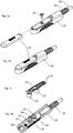
- the in 1a The elongated contact socket holder 1 shown is with two line connections, namely a four-pole first socket base 2 and with an eight-pin second socket base 3 and inserted into the rebate 4 of the door frame or door leaf 5. It is attached to or in the fold with two screws 6.
- the eight wires 9 of a connecting line 10 are soldered to the sockets of the base 3.
- a kink protection sleeve 11 surrounds the transition area between the contact sockets and the cable sheath of the connecting line 10.
- socket holders 1 together with connecting lines 10 are preferably offered preassembled with different line lengths.
- the areas of the line wire ends and their soldering points on the relevant socket base 2 and 3 as well as the sleeve-shaped holder 14 and 15, together with the contact socket holder 1, are extrusion-coated with plastic.
- the counterpart to that in the 1a and 1b reproduced socket part of the connector is the following based on the 2a to 2d described pin part.
- It consists of a connector housing 20 with an overmolded printed circuit board 21 which, according to the socket bases 2 and 3, carries two pin bases, namely a four-pin first pin base 22 and an eight-pin second pin base 23.
- the conductor tracks on the board 21 connect the contact pins with solder connections 24 for the wires of the multi-core, flexible connecting cable 25 of the cable transition.
- This connecting cable 25 is covered by a protective jacket, for. B. surrounded, not shown, tightly wound coil spring and is inserted through a screw connector 26 into the interior of the connector housing 20. The end of the coil spring is screwed onto the external thread of the connector 26.
- the circuit board 21 is how Fig. 2d shows, arranged below a chamber 27 of the connector housing 20, the shape of which is adapted to the outline of the socket holder 1.
- Two side tabs 16 and a front tab 17 on the socket holder 1 (cf. Fig 1b ) ensure in cooperation with two lateral recesses 28 and a frontal recess 29 in the wall of the chamber 27 (cf. Fig. 2d ) a reverse polarity-proof placement of the connector housing 20 on the socket holder 1.
- the two pin bases 22 and 23 are molded together with the circuit board 21.
- connection bases 2, 3 and pin bases 22, 23 can interchange their assignment to socket holder 1 and plug board 21.
- base here stands for any type of contact carrier.
- pin / socket contacts other contacts such as knife or spring contacts can be used if the installation space allows this.
- round contact bases oval or elongated contact carriers can be used with a particularly narrow installation area, which are designed, for example, as a single or double-row contact strip.
- the round shape shown in the exemplary embodiment enables the use of components which have previously been commercially available for cable transitions.
Landscapes
- Coupling Device And Connection With Printed Circuit (AREA)
- Connector Housings Or Holding Contact Members (AREA)
Claims (10)
- Connecteur à fiches électrique pour un passage de câbles flexible pouvant être séparé, comprenant un support allongé de la fiche femelle de contact (1) et une pièce de fiche mâle de contact conçue comme un pendant, et un câble de connexion (25) multifilaire flexible qui est introduit dans la pièce de fiche mâle de contact, et dans lequel le support de la fiche femelle de contact (1) comprend au moins deux raccords de ligne multipolaires (2, 3) disposés l'un à côté de l'autre dans le sens de la longueur, les contre-contacts pour les raccords de ligne (2, 3) du support de la fiche femelle de contact (1) étant disposés dans la pièce de fiche mâle de contact dans des socles de contact (22, 23) qui sont supportés par une plaquette imprimée (21) placée dans un boîtier de fiche (20) allongé, caractérisé en ce que chaque raccord de ligne (2, 3) est brasé fermement avec les fils d'une ligne de connexion (10) multifilaire d'une longueur prédéfinie.
- Connecteur à fiches selon la revendication 1, caractérisé en ce que les raccords de ligne (2, 3) sont conçus comme des réglettes de contacts à une rangée ou à plusieurs rangées s'étendant dans le sens de la longueur du support de la fiche femelle de contact (1).
- Connecteur à fiches selon la revendication 1, caractérisé en ce que les raccords de ligne (2, 3) sont conçus comme des socles femelles ou des socles mâles, ronds.
- Connecteur à fiches selon la revendication 1, caractérisé en ce que la plaquette imprimée (21) est munie d'un dispositif de connexion (24) pour les fils du câble de connexion (25) flexible.
- Connecteur à fiches selon la revendication 4, caractérisé en ce que le dispositif de connexion comprend des connexions soudées (24) pour le câble de connexion (25).
- Connecteur à fiches selon la revendication 4 ou 5, caractérisé en ce que la surface extérieure d'un manchon d'introduction (26) pour le câble de connexion (25), qui est prévu sur le boîtier de fiche (20), possède des formes empreintes pour un engagement à force avec une gaine protectrice flexible de câble.
- Connecteur à fiches selon la revendication 6, caractérisé en ce que le manchon d'introduction (26) pour le câble est pourvu d'un filetage extérieur pour visser les tours terminaux d'un ressort cylindrique enroulé de façon serrée.
- Connecteur à fiches selon l'une quelconque des revendications 1 à 7, caractérisé en ce que le support de la fiche femelle de contact (1) et le boîtier de fiche (20) comprend des moyens (16, 17; 28, 29) pour garantir une pose du boîtier de fiche sur le support de connexion sans risque d'inversion de polarité.
- Connecteur à fiches selon l'une quelconque des revendications 1 à 8, caractérisé en ce que des moyens d'étanchéité élastiques (7) sont prévu entre les pièces enfichables (2, 22; 3, 23) des deux parties du raccord (1; 20).
- Passage de câbles avec un connecteur à fiches selon l'une quelconque des revendications 1 à 9, dans lequel un tel connecteur à fiches est prévu sur chaque bout du câble de connexion (25, 26).
Applications Claiming Priority (1)
| Application Number | Priority Date | Filing Date | Title |
|---|---|---|---|
| DE102007058966A DE102007058966B3 (de) | 2007-11-30 | 2007-11-30 | Elektrische Steckverbindung für einen trennbaren Kabelübergang |
Publications (2)
| Publication Number | Publication Date |
|---|---|
| EP2065984A1 EP2065984A1 (fr) | 2009-06-03 |
| EP2065984B1 true EP2065984B1 (fr) | 2020-01-01 |
Family
ID=40280510
Family Applications (1)
| Application Number | Title | Priority Date | Filing Date |
|---|---|---|---|
| EP08020418.3A Ceased EP2065984B1 (fr) | 2007-11-30 | 2008-11-25 | Connecteur à fiches électriques pour un passage de câbles pouvant être séparé |
Country Status (2)
| Country | Link |
|---|---|
| EP (1) | EP2065984B1 (fr) |
| DE (1) | DE102007058966B3 (fr) |
Families Citing this family (1)
| Publication number | Priority date | Publication date | Assignee | Title |
|---|---|---|---|---|
| DE102012005540A1 (de) | 2012-03-21 | 2013-09-26 | Link Gmbh | Kabelübergang aus einem Stranggussformteil |
Family Cites Families (10)
| Publication number | Priority date | Publication date | Assignee | Title |
|---|---|---|---|---|
| DE9416940U1 (de) * | 1994-10-21 | 1994-12-22 | Ikon AG Präzisionstechnik, 14167 Berlin | Kabelübergangsteil |
| US5474473A (en) * | 1994-12-13 | 1995-12-12 | United Technologies Corporation | Wiring integration/backshell interface connector assembly |
| DE10053153C1 (de) * | 2000-10-26 | 2002-06-27 | Elektro Special Bedarf Link Gm | Trennbarer Kabelübergang |
| DE10126785C5 (de) * | 2001-06-01 | 2013-02-07 | Aug. Winkhaus Gmbh & Co. Kg | Kabelübergang |
| KR100414037B1 (ko) * | 2002-04-15 | 2004-01-13 | 이재욱 | 케이블 커넥팅 장치 및 이를 구비한 파티션 구조 |
| US6796844B1 (en) * | 2003-02-07 | 2004-09-28 | Cisco Technology, Inc. | System and method for coupling a plurality of cables to a device |
| US7029290B2 (en) * | 2004-08-03 | 2006-04-18 | Hon Hai Precision Ind. Co., Ltd. | Cable connector assembly having improved mating port |
| DE102004047001B4 (de) * | 2004-09-28 | 2007-03-08 | Link Gmbh | Trennbarer Kabelübergang |
| US7316584B2 (en) * | 2005-09-13 | 2008-01-08 | Deutsch Engineered Connecting Devices, Inc. | Matched impedance shielded pair interconnection system for high reliability applications |
| US7163423B1 (en) * | 2006-04-21 | 2007-01-16 | Adc Telecommunications, Inc. | Coaxial system with keying feature |
-
2007
- 2007-11-30 DE DE102007058966A patent/DE102007058966B3/de active Active
-
2008
- 2008-11-25 EP EP08020418.3A patent/EP2065984B1/fr not_active Ceased
Non-Patent Citations (1)
| Title |
|---|
| None * |
Also Published As
| Publication number | Publication date |
|---|---|
| EP2065984A1 (fr) | 2009-06-03 |
| DE102007058966B3 (de) | 2009-02-26 |
Similar Documents
| Publication | Publication Date | Title |
|---|---|---|
| EP0265698A2 (fr) | Dispositif de connexion pour la connexion électrique des branchements d'appareils électriques | |
| EP1811604A2 (fr) | Barette à bornes électriques | |
| DE19650989A1 (de) | Reihenklemme mit seitlichen Brückungskontakten | |
| WO2009127315A1 (fr) | Module de connexion | |
| DE4412968C2 (de) | Elektrischer Verbindungskasten | |
| EP2933890A1 (fr) | Insert encastré d'un appareil d'installation électrique | |
| DE102012014519B3 (de) | Verteilerbox | |
| DE102008025432A1 (de) | KLemmenanschlußblock | |
| DE102008025433B4 (de) | Klemmenanschlußblock | |
| DE102007058966B3 (de) | Elektrische Steckverbindung für einen trennbaren Kabelübergang | |
| DE69411294T2 (de) | Anschlussblock für elektrisches Geräte und Leistungsumformer mit einem derartigen Anschlu block | |
| DE19525801C2 (de) | Vorrichtung zum elektrisch leitenden Verbinden von zwei elektrischen Leitungen | |
| DE2248268A1 (de) | Zweipolige codierbare elktrische steckverbindung | |
| DE4301603C2 (de) | Fühlerkabel | |
| DE19610037C2 (de) | Baugruppenträger | |
| DE29910342U1 (de) | Vorrichtung zum Spannungsabgriff von einer elektrischen Leitung | |
| EP1039606B1 (fr) | Dispositif pour connecter électriquement au moins deux appareils electriques | |
| EP0477548A1 (fr) | Dispositif de connexion pour installations à courant faible notamment pour des services de télécommunication et de transmission de données | |
| DE19964288A1 (de) | Platinen-Hochstrom-Steckvorrichtung | |
| DE102006008971B4 (de) | Funktionsstecker und Baueinheit aus zwei elektrischen Reihenklemmen und einem Funktionsstecker | |
| DE2538199A1 (de) | Anschlussklemme fuer elektrische leitungen | |
| DE10130299A1 (de) | Elektrische Mehrfachsteckdoseneinheit | |
| DE102010039957B4 (de) | Trennbuchsenanordnungen und Trennadapter mit einer Trägerplatte und einer oder mehreren darin angebrachten Trennbuchsen der Trennbuchsenanordnungen | |
| EP0891012A2 (fr) | Dispositif de connexion électrique | |
| DE29604334U1 (de) | Verteilerkamm mit Anschlußelement |
Legal Events
| Date | Code | Title | Description |
|---|---|---|---|
| PUAI | Public reference made under article 153(3) epc to a published international application that has entered the european phase |
Free format text: ORIGINAL CODE: 0009012 |
|
| AK | Designated contracting states |
Kind code of ref document: A1 Designated state(s): AT BE BG CH CY CZ DE DK EE ES FI FR GB GR HR HU IE IS IT LI LT LU LV MC MT NL NO PL PT RO SE SI SK TR |
|
| AX | Request for extension of the european patent |
Extension state: AL BA MK RS |
|
| 17P | Request for examination filed |
Effective date: 20091013 |
|
| AKX | Designation fees paid |
Designated state(s): DE GB |
|
| 17Q | First examination report despatched |
Effective date: 20120323 |
|
| STAA | Information on the status of an ep patent application or granted ep patent |
Free format text: STATUS: EXAMINATION IS IN PROGRESS |
|
| GRAP | Despatch of communication of intention to grant a patent |
Free format text: ORIGINAL CODE: EPIDOSNIGR1 |
|
| STAA | Information on the status of an ep patent application or granted ep patent |
Free format text: STATUS: GRANT OF PATENT IS INTENDED |
|
| RIC1 | Information provided on ipc code assigned before grant |
Ipc: H01R 9/03 20060101ALI20190722BHEP Ipc: H01R 25/00 20060101ALI20190722BHEP Ipc: H01R 13/66 20060101ALN20190722BHEP Ipc: H01R 13/59 20060101ALN20190722BHEP Ipc: H01R 13/518 20060101AFI20190722BHEP Ipc: H01R 13/52 20060101ALN20190722BHEP Ipc: H01R 27/02 20060101ALI20190722BHEP Ipc: H01R 12/72 20110101ALN20190722BHEP |
|
| INTG | Intention to grant announced |
Effective date: 20190813 |
|
| GRAS | Grant fee paid |
Free format text: ORIGINAL CODE: EPIDOSNIGR3 |
|
| GRAA | (expected) grant |
Free format text: ORIGINAL CODE: 0009210 |
|
| STAA | Information on the status of an ep patent application or granted ep patent |
Free format text: STATUS: THE PATENT HAS BEEN GRANTED |
|
| AK | Designated contracting states |
Kind code of ref document: B1 Designated state(s): DE GB |
|
| REG | Reference to a national code |
Ref country code: GB Ref legal event code: FG4D Free format text: NOT ENGLISH |
|
| REG | Reference to a national code |
Ref country code: DE Ref legal event code: R096 Ref document number: 502008016995 Country of ref document: DE |
|
| RAP2 | Party data changed (patent owner data changed or rights of a patent transferred) |
Owner name: LINK GMBH |
|
| REG | Reference to a national code |
Ref country code: DE Ref legal event code: R097 Ref document number: 502008016995 Country of ref document: DE |
|
| PLBE | No opposition filed within time limit |
Free format text: ORIGINAL CODE: 0009261 |
|
| STAA | Information on the status of an ep patent application or granted ep patent |
Free format text: STATUS: NO OPPOSITION FILED WITHIN TIME LIMIT |
|
| 26N | No opposition filed |
Effective date: 20201002 |
|
| PGFP | Annual fee paid to national office [announced via postgrant information from national office to epo] |
Ref country code: GB Payment date: 20221123 Year of fee payment: 15 Ref country code: DE Payment date: 20221129 Year of fee payment: 15 |
|
| REG | Reference to a national code |
Ref country code: DE Ref legal event code: R119 Ref document number: 502008016995 Country of ref document: DE |
|
| GBPC | Gb: european patent ceased through non-payment of renewal fee |
Effective date: 20231125 |
|
| PG25 | Lapsed in a contracting state [announced via postgrant information from national office to epo] |
Ref country code: DE Free format text: LAPSE BECAUSE OF NON-PAYMENT OF DUE FEES Effective date: 20240601 |
|
| PG25 | Lapsed in a contracting state [announced via postgrant information from national office to epo] |
Ref country code: GB Free format text: LAPSE BECAUSE OF NON-PAYMENT OF DUE FEES Effective date: 20231125 |
|
| PG25 | Lapsed in a contracting state [announced via postgrant information from national office to epo] |
Ref country code: GB Free format text: LAPSE BECAUSE OF NON-PAYMENT OF DUE FEES Effective date: 20231125 Ref country code: DE Free format text: LAPSE BECAUSE OF NON-PAYMENT OF DUE FEES Effective date: 20240601 |