EP2066020A2 - Ableiten von Werten von Parametern in Elektromaschinen - Google Patents
Ableiten von Werten von Parametern in Elektromaschinen Download PDFInfo
- Publication number
- EP2066020A2 EP2066020A2 EP08253744A EP08253744A EP2066020A2 EP 2066020 A2 EP2066020 A2 EP 2066020A2 EP 08253744 A EP08253744 A EP 08253744A EP 08253744 A EP08253744 A EP 08253744A EP 2066020 A2 EP2066020 A2 EP 2066020A2
- Authority
- EP
- European Patent Office
- Prior art keywords
- value
- signal
- flux
- parameter
- linkage
- Prior art date
- Legal status (The legal status is an assumption and is not a legal conclusion. Google has not performed a legal analysis and makes no representation as to the accuracy of the status listed.)
- Withdrawn
Links
- 238000000034 method Methods 0.000 claims description 43
- 230000008859 change Effects 0.000 claims description 6
- 230000004907 flux Effects 0.000 abstract description 26
- 238000004804 winding Methods 0.000 description 12
- 238000010586 diagram Methods 0.000 description 6
- 230000010354 integration Effects 0.000 description 4
- 238000000819 phase cycle Methods 0.000 description 4
- 230000008901 benefit Effects 0.000 description 3
- 230000004069 differentiation Effects 0.000 description 3
- 238000002955 isolation Methods 0.000 description 3
- 230000003287 optical effect Effects 0.000 description 3
- 230000005355 Hall effect Effects 0.000 description 2
- 239000003990 capacitor Substances 0.000 description 2
- 230000004044 response Effects 0.000 description 2
- 238000013459 approach Methods 0.000 description 1
- 230000008878 coupling Effects 0.000 description 1
- 238000010168 coupling process Methods 0.000 description 1
- 238000005859 coupling reaction Methods 0.000 description 1
- 238000013523 data management Methods 0.000 description 1
- 230000001419 dependent effect Effects 0.000 description 1
- 238000001514 detection method Methods 0.000 description 1
- 238000006073 displacement reaction Methods 0.000 description 1
- 230000009429 distress Effects 0.000 description 1
- 238000005259 measurement Methods 0.000 description 1
- 238000012986 modification Methods 0.000 description 1
- 230000004048 modification Effects 0.000 description 1
- 230000010363 phase shift Effects 0.000 description 1
- 238000011084 recovery Methods 0.000 description 1
- 239000004065 semiconductor Substances 0.000 description 1
- 230000001360 synchronised effect Effects 0.000 description 1
Images


Classifications
-
- H—ELECTRICITY
- H02—GENERATION; CONVERSION OR DISTRIBUTION OF ELECTRIC POWER
- H02P—CONTROL OR REGULATION OF ELECTRIC MOTORS, ELECTRIC GENERATORS OR DYNAMO-ELECTRIC CONVERTERS; CONTROLLING TRANSFORMERS, REACTORS OR CHOKE COILS
- H02P25/00—Arrangements or methods for the control of AC motors characterised by the kind of AC motor or by structural details
- H02P25/02—Arrangements or methods for the control of AC motors characterised by the kind of AC motor or by structural details characterised by the kind of motor
- H02P25/08—Reluctance motors
-
- H—ELECTRICITY
- H02—GENERATION; CONVERSION OR DISTRIBUTION OF ELECTRIC POWER
- H02P—CONTROL OR REGULATION OF ELECTRIC MOTORS, ELECTRIC GENERATORS OR DYNAMO-ELECTRIC CONVERTERS; CONTROLLING TRANSFORMERS, REACTORS OR CHOKE COILS
- H02P25/00—Arrangements or methods for the control of AC motors characterised by the kind of AC motor or by structural details
- H02P25/02—Arrangements or methods for the control of AC motors characterised by the kind of AC motor or by structural details characterised by the kind of motor
- H02P25/08—Reluctance motors
- H02P25/086—Commutation
- H02P25/089—Sensorless control
-
- H—ELECTRICITY
- H02—GENERATION; CONVERSION OR DISTRIBUTION OF ELECTRIC POWER
- H02P—CONTROL OR REGULATION OF ELECTRIC MOTORS, ELECTRIC GENERATORS OR DYNAMO-ELECTRIC CONVERTERS; CONTROLLING TRANSFORMERS, REACTORS OR CHOKE COILS
- H02P6/00—Arrangements for controlling synchronous motors or other dynamo-electric motors using electronic commutation dependent on the rotor position; Electronic commutators therefor
- H02P6/14—Electronic commutators
- H02P6/16—Circuit arrangements for detecting position
Definitions
- This invention relates to deriving values of parameters in electrical machines. Particularly, but not exclusively, the invention relates to the estimation of current, voltage or flux in a brushless electrical machine.
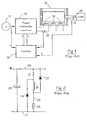
- FIG. 1 of the drawings shows a typical polyphase (in this case 3-phase) switched reluctance drive in schematic form, where the switched reluctance machine 12 is connected to a load 19.
- the input DC power supply 11 can be either a battery or rectified and filtered AC mains.
- the DC voltage provided by the power supply 11 (referred to as supply or DC link voltage below) is switched across the phase windings 16 of the machine 12 by a power converter 13 under the control of the electronic control unit 14.
- the switching must be correctly synchronised to the angle of rotation of the rotor for proper operation of the drive, and a rotor position transducer 15 may be employed to supply signals corresponding to the angular position of the rotor, ⁇ .
- an isolated form of current transducer as shown schematically at 18 in Figure 1 , can be used to provide a signal which is generally easier to use in the control system, but is considerably more expensive and may introduce problems associated with lack of bandwidth. Increasing the bandwidth of the transducer may be possible, but will increase the cost of the transducer.
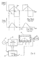
- Figure 3 shows successive cycles of the circuit shown in Figure 2 .
- the voltage is applied to the phase winding for the duration of the conduction angle ⁇ c when the switches 21 and 22 are closed at the rotor angle ⁇ on and opened at the angle ⁇ off .
- the flux which is the time integral of the applied voltage, rises almost linearly while the voltage is applied.
- the current in the phase winding 16 rises to a peak and then, depending on the operating point, falls.
- the switches are opened and the current transfers to the diodes, placing the inverted link voltage across the phase winding and hence forcing down the flux and the current to zero.
- the diodes cease to conduct and the circuit is inactive until the start of a subsequent conduction period.
- phase flux-linkage i.e. the integral of applied voltage with respect to time
- current e.g. measured by current transducer 18 in Figure 1 or by resistor 28 in Figure 2
- Position is then calculated using knowledge of the variation in inductance of the machine as a function of angle and current.
- Some applications for electrical machines require operation from a relatively low supply voltage, typically less than 50V.
- the output power requirement may only be a few kilowatts
- the current requirement is of the same order as would be found in much larger drives operating from higher voltages.
- a machine operating from a nominal 12V supply and developing 4kW will require over 400A from the supply.
- a current transducer for the phase windings for this application would require to be rated around 500A peak and, if the current signal is to be used in a position estimation algorithm, would also require to have a high bandwidth.
- the total cost of the transducers e.g. three transducers for a 3-phase system
- a method of deriving a value of a parameter in an electrical machine such as an electric or magnetic parameter of the machine.
- the method includes obtaining a position signal representative of rotor position of a rotor of the machine relative to a stator of the machine using a rotor position transducer and using this position signal to derive a value of the parameter from a relationship between the parameter and rotor position based on the magnetic characteristics of the machine.
- the parameter may be the phase current in the or a phase of the machine, which may be derived using the rotor position and a further signal representative of flux linkage.
- the flux linkage signal may be derived using a voltage transducer to measure the supply or DC link voltage.
- the parameter may be the flux linkage or supply voltage of the or a phase of the machine and may be derived using the rotor position and a further signal representative of the phase current in the phase obtained using a current transducer.
- a value for flux linkage may be calculated by integrating a measured voltage and a stored representation of a previously derived value of phase current.
- a value of supply or DC link voltage may be derived from a value of flux linkage by differentiation with respect to time.
- the value of flux linkage may be derived from measured current and rotor position values and the knowledge of the magnetic characteristics of the machine.
- the invention is suited to any electrical machine with one or more separately excitable phases. It is particularly useful in a switched reluctance machine.
- the term "position transducer” is used to denote a physical piece of hardware which gives as an output a physical, for example optical, electrical or other signal representative of the position of the moveable part of an electrical machine.
- the signal will represent angular position of the rotor: in a linear machine, the signal will represent linear displacement of the translator.
- the position transducer could be a resolver, an encoder, or a low-resolution optical or magnetic device, all as well-known in the art of position control.
- An example of a resolver is a Smartsyn ® TS2605N1 from Tamagawa Seiki Ltd.
- the term “position estimation algorithm” denotes a set of mathematical relationships which have been coded into software which, when supplied with the appropriate input signals, produces an output representing an estimate of position.
- the position estimation algorithm does not include any hardware.
- a position transducer such as the rotor position transducer 15, includes a first portion associated with the moveable part of the machine, such as a rotor, and a second portion associated with the stationary part of the machine, such as the stator.
- the first portion influences an output of the second portion as it moves, together with the moveable part, relative to the second portion.
- the output may be representative of the absolute position of the moveable part relative to the stationary part or may be representative of relative movement between the two parts.
- the output may be influenced by any physical coupling between the two portions, for example optical (transmissive or reflective), electrical (for example capacitive) or magnetic (for example based on the Hall effect).
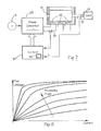
- Figure 4 An embodiment is shown schematically in Figure 4 . Like parts common to Figure 1 have been labelled accordingly. It will be noted that Figure 4 has no current transducers but has a current estimation algorithm 40 included in the control system 14'. As described above, the position transducer 15 may be any suitable hardware device which measures the angular position of the rotor and provides a suitable signal to the control system 14'.
- the current estimation algorithm takes as its inputs the position ⁇ and the flux linkage ⁇ .
- the current is known to be zero, so the correct value for phase current i can be inserted in Equation 1.
- the current is estimated (as described below), so the last available estimated current value can be inserted in the equation. Since the voltage drop across the phase winding (the iR term in Equation 1) is generally much smaller than the phase voltage (v), this is an acceptable approximation.
- the current estimation algorithm can provide a current estimate by reference to the magnetic characteristics of the machine. For example, for a magnetically doubly salient machine, there is a unique relationship between the flux linkage, position and current, as shown in Figure 5 .
- the data represented by Figure 5 can be held in one or more tables, each vector of data being indexed by rotor angle and flux-linkage. By accessing the table with known values of angle (from the position transducer) and flux-linkage (from Equation 1 above), the current can be estimated.
- the value of current thus found can be used in the control of the drive system in the same way as if it had been provided by a current transducer.
- the method can be applied simultaneously to each of the phases of a polyphase drive system and the currents thus estimated can be combined (taking account of the correct phase shift and direction of flow) to give an estimate of the DC link current and / or the supply current.
- Equation 1 The solution of Equation 1 must be done at a rate appropriate to the required response of the control system.
- the most demanding requirement for the current control aspects of the machine would be when a fault occurs and the controller has to shut the system down before damage is caused to, e.g., the power devices. This would imply a cycle time of 50 ⁇ sec for the solution of Equation 1 and look-up of the tables.
- the per-unit resistance of the machine is generally high, and may allow the system to be "resistively limited", i.e., the resistance of the phase winding is sufficient to limit the current to a value which does not cause distress to the power devices. This fact relaxes the requirement for high bandwidth in the controller and makes this embodiment particularly suitable for low-voltage, high-current drive systems.
- FIG. 6 is a block diagram schematically showing components used in the method described above.
- the position signal from the rotor position transducer 15 is decoded as necessary and stored in an appropriate register 60.
- the voltage on the DC link is sampled and stored in an appropriate register 62.
- a further register 64 holds the last computed value of current. At the start of the phase cycle the current is zero and the register 64 is set to zero.
- the register 64 is updated at the end of each iteration of the method.
- a yet further register 65 holds the value of phase resistance R. This value can be fixed or can be made to vary with, for example, the temperature of the phase winding.
- An integrator 66 integrates V-iR using the values of the registers 62, 64 and 65. There are many integration methods which are suitable, e.g. trapezoidal, Runge-Kutta, etc, all as well-known to those skilled in numerical integration.
- the output of the integrator 66 represents the derived value of flux-linkage which, together with the value of rotor position available from register 60, form the data inputs to look up table (or other data representation) 68.
- the inputs are used to interrogate the data (shown graphically in Figure 5 ) to produce the required value of current. Again, there are many different methods of storing, interrogating and interpolating the data in numerical or functional form, all well-known in the art, which could be employed to produce the required result.
- the value of current is then available for use in the control system, and can be used to update the register at 64.
- the estimation routine is then begun again, so that a continuously updated value of current is available.
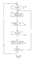
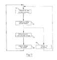
- FIG. 10 shows a flowchart illustrating method steps for deriving the value of phase current i according to the method described above.
- the current is initialised to zero at the beginning of a phase cycle. It will be understood that i may also be initialised to a suitably derived non-zero value if the machine operates in continuous current mode.
- measured values are obtained for ⁇ and the voltage and at step 104 V-iR is integrated to find a value for flux linkage ⁇ .
- the values for ⁇ and ⁇ are used to find a value for phase current i.
- the value of i is made available to the control system and is also stored for the next iteration. Then, after step 108 the method loops back to step 102. Once the end of the phase cycle is reached, the method loops back to step 100 and is ready for the next phase cycle.
- Figure 7 shows another embodiment. It is similar to Figure 4 except that there is no voltage feedback from the DC link to the controller 14". Rather, the controller receives phase current feedback from current transducer(s) 18.
- the controller 14" has a voltage estimation algorithm 40' embedded in it.
- the rotor position transducer 15 provides the required position signals, and the current transducer(s) 18 provide(s) information on phase current. If the current transducer 18 is an isolated device (e.g. a Hall-effect or flux-nulling device), then the inputs to the control system can be completely isolated from the high-voltage DC link.
- an isolated device e.g. a Hall-effect or flux-nulling device
- the magnitude of the supply voltage can be obtained from the current signal, the rotor position signal and the magnetic characteristics of the machine.
- Figure 8 shows the characteristics of a doubly salient machine in a suitable form, where flux-linkage is shown as a function of phase current and rotor position.
- this data can be held in one or more look-up tables.
- the rate of change d ⁇ /dt can be estimated by: differencing stored previously derived values of flux-linkage; a stored value and the currently estimated value of flux-linkage; or any one of the many approaches known for numerically calculating a rate of change of a signal.
- the flux-linkage signal can be used directly as one of the control signals of a flux controller for the machine. Since the torque output of the machine is more directly related to the flux than to the current, a flux controller is sometimes preferred to a current controller in order to achieve close control of the torque. This embodiment is suited to such a controller.
- This embodiment does not require a very high bandwidth in the controller, since the DC link voltage will only vary slowly in response to external disturbances. Its main advantage is that complete voltage isolation from the DC link is provided, making this embodiment particularly appropriate to high-voltage systems, where the prior art methods of isolation are cumbersome and expensive.
- Figure 9 is a block diagram schematically showing components used in the method described above in relation to Figures 7 and 8 .
- the position signal from the rotor position transducer 15 is decoded as necessary and stored in an appropriate register 90.
- the phase current is sampled and stored in an appropriate register 92.
- a further register 95 holds the value of phase resistance R. This value can be fixed or can be made to vary with, for example, the temperature of the phase winding.
- the values of registers 90 and 92 form the inputs to the data look up table (or other data interrogating means) 96.
- the inputs are used to interrogate the data (shown graphically in Figure 8 ) to produce the required value of flux-linkage.
- a differentiator 97 differentiates ⁇ to obtain d ⁇ /dt. Many differentiation methods are suitable, all as well-known to those skilled in numerical differentiation.
- a calculator 98 calculates (d ⁇ /dt + iR) to give a value of supply voltage V. This value is now available to the control system in same way that a measured value could have been used. The estimation routine is then begun again, so that a continuously updated value of voltage is available. It will be understood that the differentiator 97, the further register 95 and the calculator 98 are not required if the value of V is not needed for control, for example if control is based directly on flux linkage ⁇ .
- FIG 11 shows a flowchart illustrating method steps of the method described above in relation to Figures 7, 8 & 9 .
- steps 110 values for ⁇ and current are measured and stored and then used at step 112 to look up (or otherwise determine) a value for flux linkage ⁇ . This value is then differentiated and used to calculate a value for the phase voltage at step 114 which is output for use in controlling the machine at step 116.
- some control schemes use a flux linkage signal for control.
- an alternative step 118 of outputting the value for flux linkage ⁇ for use in controlling the machine may follow step 112. After step 116 or 118, as the case may be, the method loops back to step 110 and begins a further iteration.
Landscapes
- Engineering & Computer Science (AREA)
- Power Engineering (AREA)
- Control Of Electric Motors In General (AREA)
- Control Of Motors That Do Not Use Commutators (AREA)
- Control Of Ac Motors In General (AREA)
Applications Claiming Priority (1)
| Application Number | Priority Date | Filing Date | Title |
|---|---|---|---|
| GBGB0722919.8A GB0722919D0 (en) | 2007-11-22 | 2007-11-22 | Deriving information on parameters in electrical machines |
Publications (2)
| Publication Number | Publication Date |
|---|---|
| EP2066020A2 true EP2066020A2 (de) | 2009-06-03 |
| EP2066020A3 EP2066020A3 (de) | 2015-08-12 |
Family
ID=38925890
Family Applications (1)
| Application Number | Title | Priority Date | Filing Date |
|---|---|---|---|
| EP08253744.0A Withdrawn EP2066020A3 (de) | 2007-11-22 | 2008-11-17 | Ableiten von Werten von Parametern in Elektromaschinen |
Country Status (5)
| Country | Link |
|---|---|
| US (1) | US8121819B2 (de) |
| EP (1) | EP2066020A3 (de) |
| KR (1) | KR20090053697A (de) |
| CN (1) | CN101442285B (de) |
| GB (1) | GB0722919D0 (de) |
Families Citing this family (5)
| Publication number | Priority date | Publication date | Assignee | Title |
|---|---|---|---|---|
| GB201111602D0 (en) * | 2011-07-06 | 2011-08-24 | Nidec Sr Drives Ltd | Control of electrical machines |
| GB201222284D0 (en) * | 2012-12-11 | 2013-01-23 | Nidec Sr Drives Ltd | Estimation of resistance in electrical machines |
| JP6598563B2 (ja) * | 2015-08-05 | 2019-10-30 | ルネサスエレクトロニクス株式会社 | 信号変換器及び制御装置 |
| IT201600109364A1 (it) * | 2016-10-28 | 2018-04-28 | Ksb Ag | Metodo ed apparato per l'adattamento delle caratteristiche magnetiche di un motore sincrono a riluttanza |
| GB201621020D0 (en) * | 2016-12-09 | 2017-01-25 | Sevcon Ltd | Method and apparatus for control of switched reluctance motors |
Citations (1)
| Publication number | Priority date | Publication date | Assignee | Title |
|---|---|---|---|---|
| EP0573198A1 (de) | 1992-06-03 | 1993-12-08 | Switched Reluctance Drives Ltd | Sensorlose Rotorlagemessung in elektrischen Maschinen |
Family Cites Families (8)
| Publication number | Priority date | Publication date | Assignee | Title |
|---|---|---|---|---|
| GB9612148D0 (en) * | 1996-06-11 | 1996-08-14 | Switched Reluctance Drives Ltd | Rotor position encoder for an electrical machine |
| KR200170195Y1 (ko) * | 1997-03-18 | 2000-02-01 | 윤종용 | 스위치드 릴럭턴스 모터의 위치 감지 장치 |
| SG106576A1 (en) * | 1999-01-11 | 2004-10-29 | Switched Reluctance Drives Ltd | Rotor position detection in switched reluctance machines |
| GB9929994D0 (en) * | 1999-12-17 | 2000-02-09 | Switched Reluctance Drives Ltd | Brushless machine control |
| CN1223075C (zh) * | 2001-10-10 | 2005-10-12 | 乐金电子(天津)电器有限公司 | 开关磁阻电机驱动电路 |
| US6756757B2 (en) * | 2002-05-21 | 2004-06-29 | Emerson Electric Company | Control system and method for a rotating electromagnetic machine |
| KR101152083B1 (ko) * | 2003-04-24 | 2012-06-11 | 니덱 에스알 드라이브즈 리미티드 | 전기 기기의 회전자 위치 검출 방법 및 시스템과, 전기 기기의 회전자 위치 검출 방법을 실행하기 위한 소프트웨어를 기록한 컴퓨터가 읽을 수 있는 기록매체 |
| KR101201908B1 (ko) * | 2006-05-04 | 2012-11-16 | 엘지전자 주식회사 | 동기 릴럭턴스 모터의 제어 장치 및 방법 |
-
2007
- 2007-11-22 GB GBGB0722919.8A patent/GB0722919D0/en not_active Ceased
-
2008
- 2008-11-13 US US12/270,318 patent/US8121819B2/en not_active Expired - Fee Related
- 2008-11-13 KR KR1020080112942A patent/KR20090053697A/ko not_active Ceased
- 2008-11-17 EP EP08253744.0A patent/EP2066020A3/de not_active Withdrawn
- 2008-11-20 CN CN2008101763457A patent/CN101442285B/zh not_active Expired - Fee Related
Patent Citations (1)
| Publication number | Priority date | Publication date | Assignee | Title |
|---|---|---|---|---|
| EP0573198A1 (de) | 1992-06-03 | 1993-12-08 | Switched Reluctance Drives Ltd | Sensorlose Rotorlagemessung in elektrischen Maschinen |
Also Published As
| Publication number | Publication date |
|---|---|
| EP2066020A3 (de) | 2015-08-12 |
| CN101442285B (zh) | 2013-09-04 |
| US20090134831A1 (en) | 2009-05-28 |
| CN101442285A (zh) | 2009-05-27 |
| KR20090053697A (ko) | 2009-05-27 |
| GB0722919D0 (en) | 2008-01-02 |
| US8121819B2 (en) | 2012-02-21 |
Similar Documents
| Publication | Publication Date | Title |
|---|---|---|
| EP1139560B1 (de) | Positionserkennung einer geschalteten Reluktanzmaschine | |
| KR101517101B1 (ko) | 상전류 추정방법 | |
| EP1835613B1 (de) | System und Verfahren zum Motorgeschwindigkeitsschätzung mittels eines adaptiven Hybridmodellreferenzsystems | |
| EP1484834B9 (de) | Rotorpositionserfassung für eine geschaltete Reluktanzmaschine | |
| EP1324484B1 (de) | Rotorpositionserfassung für ein geschaltetes Reluktanzgerät | |
| US8121819B2 (en) | Deriving values of parameters in electrical machines | |
| JP5959772B2 (ja) | 制御装置 | |
| EP1553691B1 (de) | Bestimmung der Rotorposition einer elektrischen Maschine | |
| KR100720323B1 (ko) | 스위치드 릴럭턴스 머신의 회전자 위치 검출 방법 및 릴럭턴스 구동 시스템 | |
| KR20030002559A (ko) | 센서리스 비엘디씨 모터를 채용한 세탁기의 운전제어방법 | |
| EP1109308B1 (de) | Regelung für eine geschaltete Reluktanzmaschine | |
| KR101448677B1 (ko) | Bldc 모터의 회전자 위치 추정 장치 및 방법 | |
| EP4016831B1 (de) | Sensorlose steuerung eines motors durch eine variable frequenzsignalinjektion | |
| KR101429878B1 (ko) | 전기적 드라이브 시스템의 작동 | |
| JP4127000B2 (ja) | モータ制御装置 | |
| KR100408061B1 (ko) | 센서리스 비엘디씨 모터의 회전자 위치검출방법 | |
| KR20190125074A (ko) | 이상 동작 방지 알고리즘을 수행하는 모터 구동 장치 | |
| KR102509725B1 (ko) | 모터 구동 장치 | |
| KR20030002562A (ko) | 센서리스 비엘디씨 모터를 채용한 세탁기의 운전제어방법 | |
| KR102047877B1 (ko) | Pwm 신호 제어 장치 및 방법 | |
| KR20040102494A (ko) | 유도 전동기의 직접 토크 제어 장치 및 방법 |
Legal Events
| Date | Code | Title | Description |
|---|---|---|---|
| PUAI | Public reference made under article 153(3) epc to a published international application that has entered the european phase |
Free format text: ORIGINAL CODE: 0009012 |
|
| AK | Designated contracting states |
Kind code of ref document: A2 Designated state(s): AT BE BG CH CY CZ DE DK EE ES FI FR GB GR HR HU IE IS IT LI LT LU LV MC MT NL NO PL PT RO SE SI SK TR |
|
| AX | Request for extension of the european patent |
Extension state: AL BA MK RS |
|
| RAP1 | Party data changed (applicant data changed or rights of an application transferred) |
Owner name: NIDEC SR DRIVES LIMITED |
|
| RAP1 | Party data changed (applicant data changed or rights of an application transferred) |
Owner name: NIDEC SR DRIVES LTD. |
|
| PUAL | Search report despatched |
Free format text: ORIGINAL CODE: 0009013 |
|
| AK | Designated contracting states |
Kind code of ref document: A3 Designated state(s): AT BE BG CH CY CZ DE DK EE ES FI FR GB GR HR HU IE IS IT LI LT LU LV MC MT NL NO PL PT RO SE SI SK TR |
|
| AX | Request for extension of the european patent |
Extension state: AL BA MK RS |
|
| RIC1 | Information provided on ipc code assigned before grant |
Ipc: H02P 6/16 20060101ALI20150708BHEP Ipc: H02P 25/08 20060101AFI20150708BHEP |
|
| AKY | No designation fees paid | ||
| AXX | Extension fees paid |
Extension state: AL Extension state: MK Extension state: BA Extension state: RS |
|
| REG | Reference to a national code |
Ref country code: DE Ref legal event code: R108 |
|
| STAA | Information on the status of an ep patent application or granted ep patent |
Free format text: STATUS: THE APPLICATION IS DEEMED TO BE WITHDRAWN |
|
| 18D | Application deemed to be withdrawn |
Effective date: 20160213 |