EP2067719A1 - Distanzgebilde für die Leckschutzauskleidung eines Tanks, Leckschutzauskleidung und Tank mit einem solchen Distanzgebilde - Google Patents
Distanzgebilde für die Leckschutzauskleidung eines Tanks, Leckschutzauskleidung und Tank mit einem solchen Distanzgebilde Download PDFInfo
- Publication number
- EP2067719A1 EP2067719A1 EP08170804A EP08170804A EP2067719A1 EP 2067719 A1 EP2067719 A1 EP 2067719A1 EP 08170804 A EP08170804 A EP 08170804A EP 08170804 A EP08170804 A EP 08170804A EP 2067719 A1 EP2067719 A1 EP 2067719A1
- Authority
- EP
- European Patent Office
- Prior art keywords
- paper
- spacer
- tank
- lining
- coating
- Prior art date
- Legal status (The legal status is an assumption and is not a legal conclusion. Google has not performed a legal analysis and makes no representation as to the accuracy of the status listed.)
- Granted
Links
- 125000006850 spacer group Chemical group 0.000 title claims abstract description 31
- 239000011248 coating agent Substances 0.000 claims abstract description 32
- 238000000576 coating method Methods 0.000 claims abstract description 32
- 229910052751 metal Inorganic materials 0.000 claims abstract description 28
- 239000002184 metal Substances 0.000 claims abstract description 28
- 229910052782 aluminium Inorganic materials 0.000 claims abstract description 15
- XAGFODPZIPBFFR-UHFFFAOYSA-N aluminium Chemical compound [Al] XAGFODPZIPBFFR-UHFFFAOYSA-N 0.000 claims abstract description 15
- 229920003002 synthetic resin Polymers 0.000 claims abstract description 11
- 239000000057 synthetic resin Substances 0.000 claims abstract description 11
- 238000007373 indentation Methods 0.000 claims description 2
- 239000000758 substrate Substances 0.000 claims description 2
- 239000000123 paper Substances 0.000 description 63
- 239000004033 plastic Substances 0.000 description 26
- 229920003023 plastic Polymers 0.000 description 26
- 239000000463 material Substances 0.000 description 11
- 239000004744 fabric Substances 0.000 description 7
- 239000011521 glass Substances 0.000 description 7
- 229920005989 resin Polymers 0.000 description 6
- 239000011347 resin Substances 0.000 description 6
- 239000002390 adhesive tape Substances 0.000 description 5
- 239000003365 glass fiber Substances 0.000 description 5
- 239000007788 liquid Substances 0.000 description 4
- 230000002787 reinforcement Effects 0.000 description 4
- 239000000835 fiber Substances 0.000 description 3
- 238000000034 method Methods 0.000 description 3
- 238000004806 packaging method and process Methods 0.000 description 3
- 239000004593 Epoxy Substances 0.000 description 2
- 238000005452 bending Methods 0.000 description 2
- 230000015556 catabolic process Effects 0.000 description 2
- 239000011888 foil Substances 0.000 description 2
- 238000005470 impregnation Methods 0.000 description 2
- 238000007789 sealing Methods 0.000 description 2
- 238000007740 vapor deposition Methods 0.000 description 2
- 229910000831 Steel Inorganic materials 0.000 description 1
- 230000002745 absorbent Effects 0.000 description 1
- 239000002250 absorbent Substances 0.000 description 1
- 239000000853 adhesive Substances 0.000 description 1
- 230000001070 adhesive effect Effects 0.000 description 1
- 239000000919 ceramic Substances 0.000 description 1
- 239000002131 composite material Substances 0.000 description 1
- 238000010276 construction Methods 0.000 description 1
- 238000010924 continuous production Methods 0.000 description 1
- 239000003651 drinking water Substances 0.000 description 1
- 235000020188 drinking water Nutrition 0.000 description 1
- 239000003792 electrolyte Substances 0.000 description 1
- 238000005516 engineering process Methods 0.000 description 1
- 239000003822 epoxy resin Substances 0.000 description 1
- LNEPOXFFQSENCJ-UHFFFAOYSA-N haloperidol Chemical compound C1CC(O)(C=2C=CC(Cl)=CC=2)CCN1CCCC(=O)C1=CC=C(F)C=C1 LNEPOXFFQSENCJ-UHFFFAOYSA-N 0.000 description 1
- 238000009434 installation Methods 0.000 description 1
- 239000002655 kraft paper Substances 0.000 description 1
- 239000004745 nonwoven fabric Substances 0.000 description 1
- 229920003986 novolac Polymers 0.000 description 1
- 229920000647 polyepoxide Polymers 0.000 description 1
- 229920001225 polyester resin Polymers 0.000 description 1
- 239000004645 polyester resin Substances 0.000 description 1
- 229920005749 polyurethane resin Polymers 0.000 description 1
- 239000007921 spray Substances 0.000 description 1
- 239000010959 steel Substances 0.000 description 1
Images


Classifications
-
- B—PERFORMING OPERATIONS; TRANSPORTING
- B65—CONVEYING; PACKING; STORING; HANDLING THIN OR FILAMENTARY MATERIAL
- B65D—CONTAINERS FOR STORAGE OR TRANSPORT OF ARTICLES OR MATERIALS, e.g. BAGS, BARRELS, BOTTLES, BOXES, CANS, CARTONS, CRATES, DRUMS, JARS, TANKS, HOPPERS, FORWARDING CONTAINERS; ACCESSORIES, CLOSURES, OR FITTINGS THEREFOR; PACKAGING ELEMENTS; PACKAGES
- B65D90/00—Component parts, details or accessories for large containers
- B65D90/48—Arrangements of indicating or measuring devices
- B65D90/50—Arrangements of indicating or measuring devices of leakage-indicating devices
- B65D90/501—Arrangements of indicating or measuring devices of leakage-indicating devices comprising hollow spaces within walls
Definitions
- the invention relates to a spacer for the leak protection lining of a tank.
- the EP-A-1 602 597 goes back to an old technology and uses a nubbed cardboard as a spacer for a leak protection lining. However, it has been shown that the market does not want to do without checking the tightness by so-called sparking.
- the spacer according to the invention consists of a spatially shaped paper and has a metal coating.
- the necessary stiffness having material is very inexpensive.
- the paper is conductive on its surface, since there is a metal layer. This metal layer can be made extremely thin.
- the metal of the metal coating is expediently vapor-deposited on the paper. This method has the advantage that results in a complete coating and the cost of materials is very low.
- the paper is advantageously impregnated. Thanks to the impregnation, the surface of the paper is so largely closed that the vapor-deposited metal layer forms a closed layer even in a small layer thickness.
- the paper expediently has nubs on at least one side, with which it only rests selectively on a substrate.
- the cavity between the paper and the tank wall is not subdivided into different sections by any regions which lie linearly on the tank wall, but is present as an undivided space.
- the paper has expediently on the side facing the tank wall towards the first side valleys and intervening nubs and on the opposite side of the valleys corresponding ridges, and by these ridges separate, the dimples corresponding indentations.
- Such a design has been proven in non-coated according to the invention nub cardboard.
- the metal coating is advantageously mounted on the back of the nubs on the paper so that it lies in the leak-proof lining on the side of the paper facing the tank interior.
- the metal of the metal coating is advantageously aluminum.
- a leak protection lining with a spacer structure according to the invention for forming an observable cavity between the leak protection lining and the tank wall which spacer construction consists of a spatially shaped paper provided with a metal coating on at least one side
- the metal coating is expediently provided on the side of the paper provided with the synthetic resin coating.
- the invention also relates to a double-walled tank with such a leak protection lining.
- materials are suitable to create a leak protection lining in or on a tank.
- these are a flat, studded spacer structure 11 and plastic 13.
- the plastic 13 can be applied in liquid form to the spacer structure 11 and is designed in such a way that it cures to a plastic layer thereon.
- the plastic is therefore in one for liquids suitable container 19 before.
- it is a two-component plastic whose components, contrary to the illustration, are present in two separate containers.
- double-sided adhesive tape 15 For the assembly of the spacer 11 on a tank wall double-sided adhesive tape 15 may be provided.
- an aluminum adhesive tape 16 is present.
- a fiber fleece or fabric 17 may be provided.
- tools for attaching the materials are necessary. These can be spray guns, rollers, spatulas and the like.
- the illustrated spacer 11 is a napped paper.
- the paper 21 can be stored and transported as roll material. The thickness of the paper is uniform and very low. With a weight of 90 g / m 2 , a sufficient strength of the spacer 11 is achieved.
- Such a paper 21 can be impregnated with plastic 13 without experiencing substantial deformations.
- the structure of the paper 21 is characterized by intersecting grooves 23 and within the quadrilateral areas between the grooves 23, respectively, of a nub 25.
- the nub 25 may, as in FIG Figures 2 and 4 shown, having the shape of a quadrangular truncated pyramid. But you can also, as in FIG. 3 represented, cylindrical or frusto-conical. Triangular truncated pyramids are also possible.
- An aluminum layer is vapor-deposited on the dimpled paper on one side.
- This vapor-deposited metal layer is of course conductive. She is very thin. From eye, no difference in surface texture is visible when comparing uncoated and coated paper. The color of the coated surface is of course metallic, while the uncoated surface has the paper color.
- the packaging paper of about 145 microns thickness commercially available, which has grooves 23 in a diagonal square grid.
- This preferred unbleached kraft paper has a basis weight of 96 to 104 grams.
- the roughness of the unvarnished paper is reported as 1200 ⁇ 500 ml / min (Bendtsen roughness / smoothness).
- the nubs 25 are truncated pyramids, whose base has twice as long side lengths as the butt surface 27. These truncated pyramids are about 1mm high.
- the pitch of groove to groove 23 is 7 mm.
- This wrapping paper is impregnated, but porous and absorbent.
- the grooves 23 extend at an angle of 45 to the longitudinal edge 22 of this product.
- This packaging paper is coated with aluminum for coating by means of a vapor deposition system.
- the rolls are treated in a continuous process. Thanks to the impregnation of the paper, the surface structure of the paper is relatively compact. The individual fibers of the paper only rarely depend on the paper surface. As a result, an economical and complete coating is possible.
- the coating 10 may be absent by vapor deposition of aluminum on the paper 21 in an edge region. This edge region overlaps when laying the Distanzgetruckes 21 anyway.
- An electrical connection of the conductive metal layer is achieved by bonding with a conductive aluminum adhesive tape 16.
- FIG. 4 a marginal edge of the packaging paper is shown.
- the embossment of the knobs 25 and groove 23 extends over the entire surface of the paper.
- the edge of the paper therefore runs as a cutting line diagonally through the knobs and grooves. Thanks to this diagonal arrangement of the grooves 23, the grooves are even after installation of this paper as a spacer in the lining of a tank wall extending diagonally in the surfaces of the tank wall.
- FIG. 5 this course of the grooves 23 in the interior of a leak protection lining 31 is shown as dotted lines. These grooves 23 extend parallel and crosswise diagonally across the rectangular walled fourth of the tank 33rd
- the tank 33 has a dimensionally stable wall 34 in the form of a horizontal bottom 35 and four vertical walls 37.
- the wall 34 is shown as a concrete structure. It may already have an older coating. It can also consist of other materials.
- On this wall 34 a nubbed paper 21 is attached, which with the blunt surfaces 27 ( Fig. 4 ) of the nubs 25 is placed against the wall surface.
- the air volume of the grooves 23 forms an observable cavity 29 between the tank wall and the nubbed paper 21.
- the aluminum coated surface lies on the visible side of the attached nub paper. On this side facing away from the wall side of the nubbed paper 21, the concave inner sides of the nubs 25 are present as depressions between linear elevations.
- the linear elevations are the convex backsides of the grooves 23. On these coated elevations and in these coated depressions plastic is applied.
- the plastic 13 penetrates despite metal coating the entire paper 21 and forms a plastic layer 39 of at least the thickness of the paper 21.
- the fibers of the nubbed paper 21 therefore form a Faserarmtechnik the plastic layer 39. Nevertheless, the surface conductivity of the metal layer is given.
- a cover layer 41 of the coating 31 is shown.
- This top layer may consist of a plastic approved for food or drinking water, or make the coating suitable for another specific application.
- FIG. 6 is shown how the tracks of the nap paper 21 are laid in a cylindrical tank.
- tank 43 has an approximately cylindrical steel wall 45. This is occupied on its inside with a nubbed paper 21.
- the butt surfaces 27 of the nubs 25 are adjacent to the wall 45.
- the unilaterally coated with aluminum nubbed paper 21 is impregnated with a plastic and coated.
- the coating with plastic is preferably carried out in two layers. Where the stiffness of the plastic-paper composite is not sufficient, another layer can be provided with a bonded in plastic glass fleece or glass fabric.
- the webs 47 of the paper roll material 11,21 are advantageously laid in the circumferential direction of the cylinder 45.
- the grooves 23 in the nubbed paper 21 therefore extend diagonally to the generatrices of the cylinder 45 and to the circumferentially extending circular lines of the cylinder 45.
- Such a leak protection lining is created as follows: First, if necessary, a dimensionally stable wall of a tank is created or cleaned. On this tank wall 34,45 a metal-coated nubbed paper 21 is placed. The grooves 23 of the nubbed paper form intersecting channels between the paper 21 and the tank wall 34,45. The paper is laid in such a way that these channels extend at an angle that deviates significantly from 0 and 90 degrees to the bending direction of the nap paper 21. The bending direction is determined by the direction of a space edge of the surfaces to be lined or the direction of the narrowest arc of a curvature of the tank wall.
- the nubbed paper 21 holds, it can, for example, with double-sided adhesive tape 15 ( Fig. 1 ) or other adhesives are fixed to the wall 34,45. Now the nubbed paper 21 with liquid plastic 13 ( Fig. 1 ) soaked.
- plastic are primarily "epoxy novolac” and “epoxy Zycloaliphat” in question. But other epoxy resins, as well as polyurethane resins and polyester resins can be used. The synthetic resin is applied on one side.
- the nubbed paper can also be soaked with synthetic resin prior to assembly. After setting of the resin, the impregnated nubbed paper 21 is resistant to tearing. It can therefore be used with resin 13 pretreated nubbed paper 21 in areas where the nubbed paper 21 must be committed during assembly.
- the border areas can be left untreated.
- the untreated edge regions of the nubbed paper 21 can be overlapped. In the area of the overlap of adjacent nubbed paper webs, the nubs 25 and grooves 23 can be brought into conformity. As a result, the overlap practically does not contribute.
- the untreated edge areas are glued together with an aluminum strip 16. This band 16 adhesively bonds adjacent tracks together.
- the metal coating 10 forms a counter electrode extending over the entire surface of the leak protection lining.
- a two-layer glass fabric is preferred.
- the leakage protection lining produced in this way is now tested for leaks by vacuum-sealing the space between the nubbed paper and the tank wall. Air flowing in through a leak reduces the negative pressure in the intermediate space. A reduction of the negative pressure in the intermediate space therefore indicates a leak in the leak protection lining.
- This leak can now be detected by means of a high-frequency spark tester be searched. Where the spark from the device leaks onto the leak-proof lining (more specifically, the metal coating of the paper), it is potentially leaking. At these locations, the resin coating either leaks or has a bubble in it. If there are no leaks or if the leaks are sealed, the surface of the leak protection lining can still be provided with a cover layer of an application-specific plastic. This plastic is specifically designed for the liquid to be stored in the lined tank. It is also possible to cover the surface with ceramic plates.
Landscapes
- Engineering & Computer Science (AREA)
- Mechanical Engineering (AREA)
- Laminated Bodies (AREA)
- Filling Or Discharging Of Gas Storage Vessels (AREA)
Abstract
Description
- Die Erfindung betrifft ein Distanzgebilde für die Leckschutzauskleidung eines Tankes.
- Es ist bekannt, Tanks mit einer Leckschutzauskleidung zu versehen, um sie doppelwandig und damit auf Leckstellen überprüfbar zu machen. Dazu werden Distanzgebilde verwenden, die gewährleisten, dass zwischen der Leckschutzauskleidung und der äusseren Tankwandung ein Luftraum besteht, der unter Über- oder Unterdruck gesetzt werden kann, wodurch dessen Dichtigkeit und daher die Dichtigkeit der Leckschutzauskleidung überprüft werden kann. Bei der Feststellung einer Undichtigkeit besteht das Problem, diese undichte Stelle der Leckschutzauskleidung zu finden.
- Zur Überprüfung von Leckstellen in einer Kunststoffwand wurde schon vorgeschlagen, die Kunststoffwand mit einer unter Hochspannung stehenden Elektrode abzutasten und dabei eine Gegenelektrode auf der gegenüberliegenden Seite der Wandung zu verfahren.
- Aus der schweizerischen Patentschrift Nr.
532 779 - Unter anderem aus der schweizerischen Patentschrift Nr.
517 630 - Aluminiumnoppenfolien sind indessen relativ teure Bekleidungsmaterialien für Leckschutzauskleidungen.
- Die
EP -A-1 602 597 geht deshalb wieder auf eine alte Technologie zurück und verwendet einen Noppenkarton als Distanzgebilde für eine Leckschutzauskleidung. Es hat sich jedoch gezeigt, dass der Markt auf die Überprüfung der Dichtigkeit durch sogenanntes Abfunken nicht verzichten will. - Es ist daher Aufgabe der Erfindung, ein kostengünstiges Distanzgebilde vorzuschlagen, welches eine Gegenelektrode bildet und daher erlaubt, eine darüber angebrachte Kunstharzschicht durch Abtasten mit einer unter Hochspannung stehenden Elektrode auf elektrischen Durchschlag zu überprüfen.
- Erfindungsgemäss wird diese Aufgabe durch die Merkmale der unabhängigen Ansprüche gelöst. Dies bedeutet, dass das Distanzgebilde erfindungsgemäss aus einem räumlich geformten Papier besteht und eine Metallbeschichtung aufweist. Dadurch ist das die notwendige Steifigkeit aufweisende Material sehr kostengünstig. Dennoch ist das Papier an seiner Oberfläche leitend, da dort eine Metallschicht vorliegt. Diese Metallschicht kann äusserst dünn ausgebildet sein.
- Das Metall der Metallbeschichtung ist zweckmässigerweise auf das Papier aufgedampft. Dieses Verfahren hat den Vorteil, dass sich eine lückenlose Beschichtung ergibt und der Materialaufwand sehr gering ist.
- Das Papier ist vorteilhaft imprägniert. Dank der Imprägnierung ist die Oberfläche des Papiers so weitgehend geschlossen, dass die aufgedampfte Metallschicht bereits in einer geringen Schichtdicke eine geschlossene Schicht bildet.
- Das Papier weist zweckmässigerweise auf wenigstens einer Seite Noppen auf, mit denen es auf einem Untergrund lediglich punktuell aufliegt. Dadurch ist der Hohlraum zwischen dem Papier und der Tankwandung durch keine an der Tankwandung linienförmig anliegende Bereiche in verschiedene Abschnitte unterteilt, sondern liegt als ein nicht unterteilter Raum vor.
- Das Papier weist zweckmässigerweise auf der zur Tankwandung hin zu richtenden ersten Seite Täler und dazwischen sich erhebende Noppen und auf der dieser gegenüberliegenden Seite den Tälern entsprechende Grate, und durch diese Grate getrennte, den Noppen entsprechende Einbuchtungen auf. Eine solche Ausbildung hat sich bei nicht erfindungsgemäss beschichtetem Noppenkarton bewährt.
- Die Metallbeschichtung ist vorteilhaft auf der Rückseite der Noppen auf dem Papier angebracht, so dass sie in der Leckschutzauskleidung auf der dem Tankinnenraum zugewandten Seite des Papiers liegt.
- Das Metall der Metallbeschichtung ist vorteilhaft Aluminium.
- Bei einer Leckschutzauskleidung mit einem erfindungsgemässen Distanzgebilde zur Bildung eines überwachbaren Hohlraums zwischen der Leckschutzauskleidung und der Tankwandung, welches Distanzgebilde aus einem räumlich geformten und wenigstens einseitig mit einer Metallbeschichtung versehenen Papier besteht, liegt die Metallbeschichtung zweckmässigerweise auf der mit der Kunstharzbeschichtung versehenen Seite des Papiers vor. Dadurch liegt diese leitende Schicht direkt auf der Rückseite der auf Dichtigkeit zu überprüfenden Kunstharzschicht.
- Die Erfindung betrifft auch einen Doppelwandigen Tank mit einer solchen Leckschutzauskleidung.
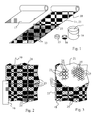
- Kurzbeschreibung der Figuren:
- Fig. 1
- zeigt eine schematische Darstellung der Materialien für eine Leckschutzauskleidung mit einem überwachbaren Hohlraum,
- Fig. 2
- zeigt schematisch einen Ausschnitt aus einem Distanzgebilde mit Pyramidenstumpfen, wobei die Kante des Rollenmaterials des Distanzgebildes teilweise mit einem Aluminiumklebeband abgedeckt ist,
- Fig. 3
- zeigt schematisch einen Ausschnitt aus einem Distanzgebilde mit Kegelstumpfen,
- Fig. 4
- zeigt eine schematische, geschnittene Perspektive eines Distanzgebildes gemäss
Fig. 2 , - Fig. 5
- zeigt schematisch einen Vertikalschnitt durch einen erfindungsgemäss ausgekleideten kubischen Tank,
- Fig. 6
- zeigt schematisch einen schiefwinkligen Vertikalschnitt durch einen erfindungsgemäss ausgekleideten zylindrischen Tank.
- Die in
Figur 1 dargestellten Materialien sind dazu geeignet, eine Leckschutzauskleidung in oder an einem Tank zu erstellen. In an sich bekannter Weise sind dies ein flächiges, genopptes Distanzgebilde 11 und Kunststoff 13. Der Kunststoff 13 ist flüssig auf das Distanzgebilde 11 auftragbar und ist derart beschaffen, dass er auf diesem zu einer Kunststoffschicht aushärtet. Der Kunststoff liegt daher in einem für Flüssigkeiten geeigneten Gebinde 19 vor. Es ist in der Regel ein Zweikomponenten-Kunststoff, dessen Komponenten entgegen der Darstellung in zwei getrennten Gebinden vorliegen. - Für die Montage des Distanzgebildes 11 an einer Tankwand kann doppelseitig klebendes Klebeband 15 vorgesehen sein. Zur Dichtung einer Fuge zwischen zwei Bahnen und zum elektrischen Verbinden der Beschichtung ist eine Aluminium-Klebeband 16 vorhanden. Für eine Verstärkung der Beschichtung kann ein Faser-Vlies oder -Gewebe 17 vorgesehen sein. Zudem sind Werkzeuge zum Anbringen der Materialien notwendig. Dies können Spritzpistolen, Roller, Spachtel und dergleichen sein.
- Das dargestellte Distanzgebilde 11 ist genopptes Papier. Das Papier 21 ist als Rollenmaterial lager- und transportierbar. Die Dicke des Papiers ist gleichmässig und sehr gering. Mit einem Gewicht von 90 g/m2 ist eine genügende Festigkeit des Distanzgebildes 11 erreicht. Ein solches Papier 21 kann, ohne dabei wesentliche Verformungen zu erfahren, mit Kunststoff 13 getränkt werden. Die Struktur des Papiers 21 ist charakterisiert durch sich kreuzende Rillen 23 und innerhalb der viereckigen Flächen zwischen den Rillen 23 jeweils einer Noppe 25. Die Noppe 25 kann, wie in
Figuren 2 und4 dargestellt, die Form eines viereckigen Pyramidenstumpfs aufweisen. Sie kann aber auch, wie inFigur 3 dargestellt, zylindrisch oder kegelstumpfförmig sein. Dreieckige Pyramidenstumpfe sind ebenfalls möglich. - Auf das genoppte Papier ist auf der einen Seite eine Aluminiumschicht aufgedampft. Diese aufgedampfte Metallschicht ist natürlich leitend. Sie ist sehr dünn. Von Auge ist beim Vergleich eines unbeschichteten und eines beschichteten Papiers kein Unterschied der Oberflächenstruktur sichtbar. Die Farbe der beschichteten Oberfläche ist selbstverständlich metallisch, während die unbeschichtete Oberfläche die Papierfarbe aufweist.
- Es ist ein Verpackungspapier mit ca. 145 Mikrometer Dicke im Handel erhältlich, welches Rillen 23 in einem diagonalen quadratischen Raster aufweist. Dieses bevorzugte ungebleichte Kraft-Papier weist ein Flächengewicht von 96 bis 104 Gramm auf. Die Rauheit des noch nicht bedampften Papiers wird mit 1200 ±500 ml/min angegeben (Rauheit/Glätte nach Bendtsen). Die Noppen 25 sind Pyramidenstumpfe, deren Basis eine doppelt so lange Seitenlängen aufweist wie deren Stumpffläche 27. Diese Pyramidenstumpfe sind etwa 1mm hoch. Das Rastermass von Rille zu Rille 23 ist 7 mm. Dieses Verpackungspapier ist imprägniert, jedoch offenporig und saugfähig. Die Rillen 23 verlaufen in einem Winkel von 45 zum Längsrand 22 dieser Rollenware.
- Dieses Verpackungspapier wird zur Beschichtung mittels einer Bedampfungsanlage mit Aluminium bedampft. Die Rollenware wird dazu in einem kontinuierlichen Verfahren behandelt. Dank der Imprägnierung des Papiers ist die Oberflächenstruktur des Papiers relativ kompakt. Die einzelnen Fasern des Papiers stehen nur selten von der Papieroberfläche ab. Dadurch ist eine ökonomische und lückenlose Beschichtung möglich.
- Wie aus den
Figuren 1 bis 3 ersichtlich, kann die Beschichtung 10 durch Aufdampfen von Aluminium auf das Papier 21 in einem Randbereich fehlen. Dieser Randbereich überlappt beim Verlegen der Distanzgebildes 21 ohnehin. Eine elektrische Verbindung der leitenden Metallschicht wird durch ein Verkleben mit einem leitenden Aluminium-Klebeband 16 erreicht. - In
Figur 4 ist eine Randkante des Verpackungspapiers dargestellt. Die Prägung der Noppen 25 und Rille 23 verläuft über die gesamte Fläche des Papiers. Der Rand des Papiers verläuft daher als Schnittlinie diagonal durch die Noppen und Rillen. Dank dieser diagonalen Anordnung der Rillen 23 sind die Rillen auch nach Einbau dieses Papiers als Distanzgebilde in der Auskleidung einer Tankwand diagonal verlaufend in den Flächen der Tankwandung. - In
Figur 5 ist dieser Verlauf der Rillen 23 im Innern einer Leckschutzauskleidung 31 als punktierte Linien dargestellt. Diese Rillen 23 verlaufen parallel und kreuzweise diagonal über die rechteckigen Wandgevierte des Tankes 33. - Der Tank 33 besitzt eine formfeste Wandung 34 in Form eines horizontalen Bodens 35 und vier vertikaler Wände 37. Die Wandung 34 ist als Betonkonstruktion dargestellt. Sie kann bereits eine ältere Beschichtung aufweisen. Sie kann auch aus anderen Materialien bestehen. Auf diese Wandung 34 ist ein Noppenpapier 21 angebracht, welches mit den Stumpfflächen 27 (
Fig. 4 ) der Noppen 25 gegen die Wandungsoberfläche gelegt ist. Das Luftvolumen der Rillen 23 bildet einen überwachbaren Hohlraum 29 zwischen der Tankwandung und dem Noppenpapier 21. Die aluminiumbeschichtete Oberfläche liegt auf der sichtbaren Seite des angebrachten Noppenpapiers. Auf dieser von der Wandung abgewandten Seite des Noppenpapiers 21 liegen die konkaven Innenseiten der Noppen 25 als Vertiefungen zwischen linearen Erhebungen vor. Die linearen Erhebungen sind die konvexen Rückseiten der Rillen 23. Auf diese beschichteten Erhebungen und in diese beschichteten Vertiefungen ist Kunststoff aufgetragen. Der Kunststoff 13 durchdringt trotz Metallbeschichtung das gesamte Papier 21 und bildet eine Kunststoffschicht 39 von wenigstens der Stärke des Papiers 21. Die Fasern des Noppenpapiers 21 bilden daher eine Faserarmierung der Kunststoffschicht 39. Dennoch ist die flächige Leitfähigkeit der Metallschicht gegeben. - In den Kunststoff 13 der Kunststoffschicht 39 ist gemäss
Figur 5 jedoch vorteilhaft auch eine Glasfaserarmierung 17 eingelegt. Diese Glasfaserarmierung ist ein Zweischichtglasgewebe 17. Dieses Zweischichtglasgewebe 17 ist in der Kunststoffschicht 39 eingeschlossen. - In
Figur 5 ist zudem eine Deckschicht 41 der Beschichtung 31 dargestellt. Diese Deckschicht kann aus einem für Lebensmittel oder Trinkwasser zugelassenen Kunststoff bestehen, oder die Beschichtung für einen anderen speziellen Einsatzbereich geeignet machen. - In
Figur 6 ist dargestellt, wie die Bahnen des Noppenpapiers 21 in einem zylindrischen Tank verlegt sind. Der inFigur 6 dargestellte Tank 43 besitzt eine etwa zylindrische Stahlwandung 45. Diese ist auf ihrer Innenseite mit einem Noppenpapier 21 belegt. Die Stumpfflächen 27 der Noppen 25 (sieheFig. 4 ) sind an die Wandung 45 anliegend. Das einseitig mit Aluminium bedampfte Noppenpapier 21 ist mit einem Kunststoff getränkt und überzogen. Die Beschichtung mit Kunststoff ist vorzugsweise in zwei Lagen ausgeführt. Wo die Steifigkeit des Kunststoff-Papier-Verbundes nicht ausreicht, kann eine weitere Lage mit einem in Kunststoff gebundenem Glasvlies oder Glasgewebe vorgesehen sein. - Die Bahnen 47 des papierenen Rollenmaterials 11,21 sind vorteilhaft in Umfangrichtung des Zylinders 45 verlegt. Die Rillen 23 im Noppenpapier 21 verlaufen daher diagonal zu den Mantellinien des Zylinders 45 und zu den in Umfangrichtung verlaufenden Kreislinien des Zylinders 45.
- Erstellt wird eine solche Leckschutzauskleidung wie folgt: Zuerst wird gegebenenfalls eine formfeste Wandung eines Tankes erstellt oder gereinigt. Auf diese Tankwandung 34,45 wird ein metallbeschichtetes Noppenpapier 21 aufgelegt. Die Rillen 23 des Noppenpapiers bilden dabei sich kreuzende Kanäle zwischen dem Papier 21 und der Tankwandung 34,45. Das Papier wird derart verlegt, dass diese Kanäle in einem Winkel, der deutlich von 0 und 90 Grad abweicht, zur Biegerichtung des Noppenpapiers 21 verlaufen. Die Biegerichtung wird durch die Richtung einer Raumkante der auszukleidenden Flächen oder die Richtung des engsten Bogens einer Wölbung der Tankwandung bestimmt.
- Damit das Noppenpapier 21 hält, kann es z.B. mit zweiseitig klebendem Band 15 (
Fig. 1 ) oder anderen Klebemitteln an der Wandung 34,45 fixiert werden. Nun wird das Noppenpapier 21 mit flüssigem Kunststoff 13 (Fig. 1 ) getränkt. Als Kunststoff kommen in erster Linie "Epoxy Novolac" und "Epoxy Zycloaliphat" in Frage. Aber auch andere Epoxyharze, wie auch Polyurethanharze und Polyesterharze können verwendet werden. Der Kunstharz wird dazu einseitig aufgetragen. - Das Noppenpapier kann auch vor der Montage mit Kunstharz getränkt werden. Nach dem Abbinden des Kunstharzes ist das getränkte Noppenpapier 21 trittfest. Es kann daher mit Kunstharz 13 vorbehandeltes Noppenpapier 21 in Bereichen eingesetzt werden, in denen das Noppenpapier 21 bei der Montage begangen werden muss.
- Zweckmässigerweise wird das mit Kunststoff vorbehandelte Noppenpapier 21 aber nicht über die gesamte Bahnbreite getränkt. Die Randbereiche können unbehandelt bleiben. Die unbehandelten Randbereiche des Noppenpapiers 21 können überlappt werden. Im Bereich der Überlappung benachbarter Noppenpapier-Bahnen können die Noppen 25 und Rillen 23 in Übereinstimmung gebracht werden. Dadurch trägt die Überlappung praktisch nicht auf. Die unbehandelten Randbereiche werden mit einem Aluminiumband 16 miteinander verklebt. Diese Band 16 klebt benachbarte Bahnen elektrisch leitend miteinander. Dadurch bildet die Metallbeschichtung 10 eine über die gesamte Fläche der Leckschutzauskleidung verlaufende Gegenelektrode.
- Die Überlappungen und die ganzen nicht vorbehandelten Noppenpapierbahnen werden mit Kunststoff getränkt. Vorbehandelte Bereiche können mit Kunstharz überdeckt werden. In den vorzugsweise noch nassen Kunstharz wird nun eine Glasfaserarmierung eingelegt und mit Rollen angedrückt. Kunstharz wird in die Glasfaserarmierung eingetragen. Sollten sich zwischen dem Noppenpapier und der Glasfaserarmierung Blasen bilden, werden diese mit Rollen an den Rand der Glasfaserbahnen gedrängt und so das Glasfaservlies oder das Glasgewebe praktisch blasenfrei in den Kunstharz eingebettet.
- Bevorzugt wird ein Glasgewebe, welches eine gegenüber herkömmlichen Vliesen grössere Eigenstabilität aufweist. Besonders wird ein Zweischichtglasgewebe bevorzugt.
- Die so hergestellte Leckschutzauskleidung wird nun auf Dichtigkeit geprüft, indem der Zwischenraum zwischen dem Noppenpapier und der Tankwandung vakuumiert wird. Durch ein Leck einströmende Luft reduziert den Unterdruck im Zwischenraum. Eine Reduktion des Unterdrucks im Zwischenraum zeigt daher ein Leck in der Leckschutzauskleidung an. Dieses Leck kann nun mittels eines Hochfrequenz-Funkenprüfgeräts gesucht werden. Stellen, bei denen der Funken vom Gerät auf die Leckschutzauskleidung (genauer auf die Metallbeschichtung des Papiers) überspringt, sind potentiell undicht. An diesen Stellen ist die Kunstharz-Beschichtung entweder undicht oder sie weist eine Blase darin auf. Sind keine Leckstellen vorhanden oder sind die Leckstellen gedichtet, so kann die Oberfläche der Leckschutzauskleidung noch mit einer Deckschicht eines anwendungsspezifischen Kunststoffes versehen werden. Dieser Kunststoff ist spezifisch auf die Flüssigkeit, welche im ausgekleideten Tank aufbewahrt werden soll, ausgelegt. Es ist auch möglich, die Oberfläche mit keramischen Platten zu belegen.
Claims (10)
- Distanzgebilde (11) für eine Leckschutzauskleidung, um zwischen einer Tankwandung (34,45) und einer Beschichtung (39) des Distanzgebildes (11) einen überwachbaren Hohlraum (29) zu bilden, bestehend aus einem räumlich geformten Papier (21),, dadurch gekennzeichnet, dass das räumlich geformte Papier (21) eine Metallbeschichtung (10) aufweist.
- Distanzgebilde nach Anspruch 1, dadurch gekennzeichnet, dass das Metall der Metallbeschichtung (10) auf das Papier (21) aufgedampft ist.
- Distanzgebilde nach Anspruch 1 oder 2, dadurch gekennzeichnet, dass das Papier (21) imprägniert ist.
- Distanzgebilde nach einem der Ansprüche 1 bis 3, dadurch gekennzeichnet, dass das Papier auf wenigstens einer Seite Noppen aufweist, so dass es mit dieser Seite auf einem Untergrund lediglich punktuell aufliegt.
- Distanzgebilde nach Anspruch 4, dadurch gekennzeichnet, dass das Papier (21) auf der zur Tankwandung (34) hin zu richtenden ersten Seite des Papiers Täler (23) und dazwischen sich erhebende Noppen (25) und auf der dieser gegenüberliegenden Seite den Tälern (23) entsprechende Grate, und durch diese Grate getrennte, den Noppen (25) entsprechende Einbuchtungen aufweist.
- Distanzgebilde nach einem der Ansprüche 4 oder 5, dadurch gekennzeichnet, dass die Metallbeschichtung (10) auf der Rückseite der Noppen (25) auf dem Papier (21) angebracht ist.
- Distanzgebilde nach einem der Ansprüche 1 bis 6, dadurch gekennzeichnet, dass das Metall der Metallbeschichtung (10) Aluminium ist.
- Leckschutzauskleidung mit einem Distanzgebilde (11) zur Bildung eines überwachbaren Hohlraums (29) zwischen der Leckschutzauskleidung und der Tankwandung (34), welches Distanzgebilde (11) aus einem räumlich geformten Papier (21) besteht, und mit einer Kunstharzbeschichtung (39) versehen ist, dadurch gekennzeichnet, dass das Distanzgebilde (11) ein Distanzgebilde gemäss einem der Ansprüche 1 bis 7 ist.
- Leckschutzauskleidung nach Anspruch 8, dadurch gekennzeichnet, dass die Metallbeschichtung (10) auf der mit der Kunstharzbeschichtung (39) versehenen Seite des Papiers (21) vorliegt.
- Doppelwandiger Tank mit einer Leckschutzauskleidung gemäss einem der Ansprüche 8 oder 9.
Applications Claiming Priority (1)
| Application Number | Priority Date | Filing Date | Title |
|---|---|---|---|
| CH18762007 | 2007-12-05 |
Publications (2)
| Publication Number | Publication Date |
|---|---|
| EP2067719A1 true EP2067719A1 (de) | 2009-06-10 |
| EP2067719B1 EP2067719B1 (de) | 2012-02-01 |
Family
ID=40384764
Family Applications (1)
| Application Number | Title | Priority Date | Filing Date |
|---|---|---|---|
| EP08170804A Not-in-force EP2067719B1 (de) | 2007-12-05 | 2008-12-05 | Distanzgebilde für die Leckschutzauskleidung eines Tanks, Leckschutzauskleidung und Tank mit einem solchen Distanzgebilde |
Country Status (2)
| Country | Link |
|---|---|
| EP (1) | EP2067719B1 (de) |
| AT (1) | ATE543756T1 (de) |
Cited By (9)
| Publication number | Priority date | Publication date | Assignee | Title |
|---|---|---|---|---|
| RU2504508C1 (ru) * | 2012-12-18 | 2014-01-20 | Федеральное государственное бюджетное образовательное учреждение высшего профессионального образования "Донской государственный технический университет" | Бак для агрессивной жидкости |
| CN103552778A (zh) * | 2013-11-07 | 2014-02-05 | 坚保復合材料(中山)有限公司 | 用于双壁储罐的夹层板 |
| ITVR20120180A1 (it) * | 2012-09-07 | 2014-03-08 | Ag | Metodo per realizzare una parete interna di metallo in un serbatoio e serbatoio avente una doppia parete. |
| CN104118672A (zh) * | 2014-07-10 | 2014-10-29 | 坚保復合材料(中山)有限公司 | 一种带壁体破裂检测装置的双壁储罐 |
| CN104118668A (zh) * | 2014-07-10 | 2014-10-29 | 坚保復合材料(中山)有限公司 | 一种新型双壁储罐 |
| CN104118667A (zh) * | 2014-07-10 | 2014-10-29 | 坚保復合材料(中山)有限公司 | 一种双壁储罐的壁体结构 |
| CN105253479A (zh) * | 2015-11-12 | 2016-01-20 | 青岛诺诚化学品安全科技有限公司 | 双层储油罐 |
| CN105270773A (zh) * | 2015-11-12 | 2016-01-27 | 青岛诺诚化学品安全科技有限公司 | 双层储油罐 |
| AT518760A1 (de) * | 2016-06-13 | 2017-12-15 | Wolftank-Adisa Holding Ag | Leckschutzfolie für einen Fluidtank |
Families Citing this family (1)
| Publication number | Priority date | Publication date | Assignee | Title |
|---|---|---|---|---|
| DE102016121348A1 (de) | 2016-11-08 | 2018-05-09 | W+H Tankschutz Gmbh | Innenauskleidung für einen Tank und Tankanordnung |
Citations (8)
| Publication number | Priority date | Publication date | Assignee | Title |
|---|---|---|---|---|
| US3525452A (en) * | 1967-03-31 | 1970-08-25 | Linde Ag | Method and device for thermally insulating a vessel |
| CH517630A (de) | 1969-12-23 | 1972-01-15 | Borsari & Co | Flüssigkeitsbehälter |
| CH532779A (de) | 1972-07-01 | 1973-01-15 | H Schaerer Max | Verfahren zum Auffinden undichter Stellen eines doppelwandigen Behälters oder Behälterteils und Einrichtung zur Durchführung des Verfahrens |
| DE2158089A1 (de) * | 1971-11-24 | 1973-05-30 | Robert Dipl Ing Heidenreich | Ueberwachungseinrichtung fuer kunststoffbehaelter |
| JPS5697700A (en) * | 1979-12-29 | 1981-08-06 | Nippon Telegr & Teleph Corp <Ntt> | Heat insulation method for low temperature |
| CH638150A5 (en) * | 1979-01-12 | 1983-09-15 | Rudolf Grossenbacher | Method for lining a liquid tank to be resistant to petrol, heating oil and alcohol |
| EP0754635A1 (de) * | 1995-07-17 | 1997-01-22 | Adisa Service und Entwicklungs AG | Doppelwandiger Tank und Verfahren zu dessen Herstellung |
| EP1602597A1 (de) | 2004-04-30 | 2005-12-07 | Adisa Service und Entwicklungs AG | Tank-Innenbeschichtung mit Distantznoppen |
-
2008
- 2008-12-05 EP EP08170804A patent/EP2067719B1/de not_active Not-in-force
- 2008-12-05 AT AT08170804T patent/ATE543756T1/de active
Patent Citations (8)
| Publication number | Priority date | Publication date | Assignee | Title |
|---|---|---|---|---|
| US3525452A (en) * | 1967-03-31 | 1970-08-25 | Linde Ag | Method and device for thermally insulating a vessel |
| CH517630A (de) | 1969-12-23 | 1972-01-15 | Borsari & Co | Flüssigkeitsbehälter |
| DE2158089A1 (de) * | 1971-11-24 | 1973-05-30 | Robert Dipl Ing Heidenreich | Ueberwachungseinrichtung fuer kunststoffbehaelter |
| CH532779A (de) | 1972-07-01 | 1973-01-15 | H Schaerer Max | Verfahren zum Auffinden undichter Stellen eines doppelwandigen Behälters oder Behälterteils und Einrichtung zur Durchführung des Verfahrens |
| CH638150A5 (en) * | 1979-01-12 | 1983-09-15 | Rudolf Grossenbacher | Method for lining a liquid tank to be resistant to petrol, heating oil and alcohol |
| JPS5697700A (en) * | 1979-12-29 | 1981-08-06 | Nippon Telegr & Teleph Corp <Ntt> | Heat insulation method for low temperature |
| EP0754635A1 (de) * | 1995-07-17 | 1997-01-22 | Adisa Service und Entwicklungs AG | Doppelwandiger Tank und Verfahren zu dessen Herstellung |
| EP1602597A1 (de) | 2004-04-30 | 2005-12-07 | Adisa Service und Entwicklungs AG | Tank-Innenbeschichtung mit Distantznoppen |
Cited By (11)
| Publication number | Priority date | Publication date | Assignee | Title |
|---|---|---|---|---|
| ITVR20120180A1 (it) * | 2012-09-07 | 2014-03-08 | Ag | Metodo per realizzare una parete interna di metallo in un serbatoio e serbatoio avente una doppia parete. |
| EP2706021A1 (de) * | 2012-09-07 | 2014-03-12 | Wolftank Systems S.p.A. | Verfahren zur Herstellung einer inneren Metallwand in einem Tank und Tank mit einer doppelten Wand |
| RU2504508C1 (ru) * | 2012-12-18 | 2014-01-20 | Федеральное государственное бюджетное образовательное учреждение высшего профессионального образования "Донской государственный технический университет" | Бак для агрессивной жидкости |
| CN103552778A (zh) * | 2013-11-07 | 2014-02-05 | 坚保復合材料(中山)有限公司 | 用于双壁储罐的夹层板 |
| CN104118672A (zh) * | 2014-07-10 | 2014-10-29 | 坚保復合材料(中山)有限公司 | 一种带壁体破裂检测装置的双壁储罐 |
| CN104118668A (zh) * | 2014-07-10 | 2014-10-29 | 坚保復合材料(中山)有限公司 | 一种新型双壁储罐 |
| CN104118667A (zh) * | 2014-07-10 | 2014-10-29 | 坚保復合材料(中山)有限公司 | 一种双壁储罐的壁体结构 |
| CN105253479A (zh) * | 2015-11-12 | 2016-01-20 | 青岛诺诚化学品安全科技有限公司 | 双层储油罐 |
| CN105270773A (zh) * | 2015-11-12 | 2016-01-27 | 青岛诺诚化学品安全科技有限公司 | 双层储油罐 |
| AT518760A1 (de) * | 2016-06-13 | 2017-12-15 | Wolftank-Adisa Holding Ag | Leckschutzfolie für einen Fluidtank |
| AT518760B1 (de) * | 2016-06-13 | 2018-04-15 | Wolftank Adisa Holding Ag | Leckschutzfolie für einen Fluidtank |
Also Published As
| Publication number | Publication date |
|---|---|
| ATE543756T1 (de) | 2012-02-15 |
| EP2067719B1 (de) | 2012-02-01 |
Similar Documents
| Publication | Publication Date | Title |
|---|---|---|
| EP2067719B1 (de) | Distanzgebilde für die Leckschutzauskleidung eines Tanks, Leckschutzauskleidung und Tank mit einem solchen Distanzgebilde | |
| EP0470321B1 (de) | Tank und Verfahren zur Herstellung desselben | |
| DE3622593A1 (de) | Stehtank und verfahren zur herstellung desselben | |
| EP1073597B1 (de) | Flachbodentank und verfahren zu dessen ausrüstung mit einer leckschutzauskleidung | |
| DE10140467A1 (de) | Dichter und thermisch isolierender Tank mit verbesserten Längskanten | |
| EP1602597B1 (de) | Tank-Innenbeschichtung mit Distantznoppen | |
| DE69400949T2 (de) | Verfahren zum Errichten eines Silos bzw. Tanks mit Auskleidung sowie Wandplatte zum Errichten eines Silos bzw. Tanks und Verfahren zur Herstellung einer solchen Wandplatte | |
| CH695701A5 (de) | Leichtbau-Verbundelement, sein Herstellungsverfahren und seine Verwendung. | |
| CH638150A5 (en) | Method for lining a liquid tank to be resistant to petrol, heating oil and alcohol | |
| EP1373075B1 (de) | Verbindungssystem zur befestigung einer flexiblen kunsstofffolie zur leckschutz-auskleidung an der innenseite der tankwandung eines lagertanks | |
| DE102013004021B4 (de) | Behälter für feste, flüssige oder gasförmige Medien | |
| EP0915755B1 (de) | Bitumenbahn | |
| DE2623321C2 (de) | Boden nach DIN 18032 | |
| EP2527530B1 (de) | Bituminöse Dachbahn | |
| DE3308941C2 (de) | Plattenförmiges Wärmedämmelement | |
| EP0673341A1 (de) | Doppelplatte und verfahren zu ihrer herstellung. | |
| WO1994012736A1 (de) | Messelektrode für leckortungssysteme | |
| DE102016121348A1 (de) | Innenauskleidung für einen Tank und Tankanordnung | |
| EP1339624B1 (de) | Flüssigkeitsbehälter sowie mittel und verfahren zur auskleidung derselben | |
| EP1426528B1 (de) | Wasserreservoir, sowie Verfahren zu dessen Herstellung oder Sanierung | |
| WO2007087832A1 (de) | Abdeckelement zum schutz von bauwerksteilen und walze zu dessen herstellung | |
| DE4000442A1 (de) | Lagerbehaelter fuer fluessigkeiten und verfahren zum anbringen einer behaelterauskleidung | |
| AT379422B (de) | Verfahren zum ueberwachen doppelwandiger abdichtungen an bauwerken und material zur herstellung der abdichtungen | |
| DE4343792A1 (de) | Unterirdischer Lagerbehälter für Flüssigkeiten | |
| DE102023003225A1 (de) | Einrichtung für wenigstens einen Behälter zur Speicherung von gasförmigen oder flüssigen Medien, insbesondere Biogasbehälter |
Legal Events
| Date | Code | Title | Description |
|---|---|---|---|
| PUAI | Public reference made under article 153(3) epc to a published international application that has entered the european phase |
Free format text: ORIGINAL CODE: 0009012 |
|
| AK | Designated contracting states |
Kind code of ref document: A1 Designated state(s): AT BE BG CH CY CZ DE DK EE ES FI FR GB GR HR HU IE IS IT LI LT LU LV MC MT NL NO PL PT RO SE SI SK TR |
|
| AX | Request for extension of the european patent |
Extension state: AL BA MK RS |
|
| 17P | Request for examination filed |
Effective date: 20091130 |
|
| 17Q | First examination report despatched |
Effective date: 20091229 |
|
| AKX | Designation fees paid |
Designated state(s): AT BE BG CH CY CZ DE DK EE ES FI FR GB GR HR HU IE IS IT LI LT LU LV MC MT NL NO PL PT RO SE SI SK TR |
|
| GRAP | Despatch of communication of intention to grant a patent |
Free format text: ORIGINAL CODE: EPIDOSNIGR1 |
|
| GRAS | Grant fee paid |
Free format text: ORIGINAL CODE: EPIDOSNIGR3 |
|
| GRAA | (expected) grant |
Free format text: ORIGINAL CODE: 0009210 |
|
| AK | Designated contracting states |
Kind code of ref document: B1 Designated state(s): AT BE BG CH CY CZ DE DK EE ES FI FR GB GR HR HU IE IS IT LI LT LU LV MC MT NL NO PL PT RO SE SI SK TR |
|
| REG | Reference to a national code |
Ref country code: GB Ref legal event code: FG4D Free format text: NOT ENGLISH |
|
| REG | Reference to a national code |
Ref country code: AT Ref legal event code: REF Ref document number: 543756 Country of ref document: AT Kind code of ref document: T Effective date: 20120215 Ref country code: CH Ref legal event code: EP |
|
| REG | Reference to a national code |
Ref country code: DE Ref legal event code: R082 Ref document number: 502008006292 Country of ref document: DE Representative=s name: KOENIG SZYNKA TILMANN VON RENESSE, DE Ref country code: DE Ref legal event code: R082 Ref document number: 502008006292 Country of ref document: DE Representative=s name: KOENIG SZYNKA TILMANN VON RENESSE PATENTANWAEL, DE Ref country code: DE Ref legal event code: R082 Ref document number: 502008006292 Country of ref document: DE Representative=s name: DR. PAETZOLD, TANDLER, RIEGGER & KOLLEGEN, DE |
|
| REG | Reference to a national code |
Ref country code: DE Ref legal event code: R096 Ref document number: 502008006292 Country of ref document: DE Effective date: 20120322 |
|
| REG | Reference to a national code |
Ref country code: CH Ref legal event code: NV Representative=s name: DR. GRAF & PARTNER AG INTELLECTUAL PROPERTY |
|
| REG | Reference to a national code |
Ref country code: NL Ref legal event code: VDEP Effective date: 20120201 |
|
| LTIE | Lt: invalidation of european patent or patent extension |
Effective date: 20120201 |
|
| PG25 | Lapsed in a contracting state [announced via postgrant information from national office to epo] |
Ref country code: NL Free format text: LAPSE BECAUSE OF FAILURE TO SUBMIT A TRANSLATION OF THE DESCRIPTION OR TO PAY THE FEE WITHIN THE PRESCRIBED TIME-LIMIT Effective date: 20120201 Ref country code: LT Free format text: LAPSE BECAUSE OF FAILURE TO SUBMIT A TRANSLATION OF THE DESCRIPTION OR TO PAY THE FEE WITHIN THE PRESCRIBED TIME-LIMIT Effective date: 20120201 Ref country code: IS Free format text: LAPSE BECAUSE OF FAILURE TO SUBMIT A TRANSLATION OF THE DESCRIPTION OR TO PAY THE FEE WITHIN THE PRESCRIBED TIME-LIMIT Effective date: 20120601 Ref country code: HR Free format text: LAPSE BECAUSE OF FAILURE TO SUBMIT A TRANSLATION OF THE DESCRIPTION OR TO PAY THE FEE WITHIN THE PRESCRIBED TIME-LIMIT Effective date: 20120201 Ref country code: NO Free format text: LAPSE BECAUSE OF FAILURE TO SUBMIT A TRANSLATION OF THE DESCRIPTION OR TO PAY THE FEE WITHIN THE PRESCRIBED TIME-LIMIT Effective date: 20120501 |
|
| REG | Reference to a national code |
Ref country code: IE Ref legal event code: FD4D |
|
| PG25 | Lapsed in a contracting state [announced via postgrant information from national office to epo] |
Ref country code: PT Free format text: LAPSE BECAUSE OF FAILURE TO SUBMIT A TRANSLATION OF THE DESCRIPTION OR TO PAY THE FEE WITHIN THE PRESCRIBED TIME-LIMIT Effective date: 20120601 Ref country code: FI Free format text: LAPSE BECAUSE OF FAILURE TO SUBMIT A TRANSLATION OF THE DESCRIPTION OR TO PAY THE FEE WITHIN THE PRESCRIBED TIME-LIMIT Effective date: 20120201 Ref country code: LV Free format text: LAPSE BECAUSE OF FAILURE TO SUBMIT A TRANSLATION OF THE DESCRIPTION OR TO PAY THE FEE WITHIN THE PRESCRIBED TIME-LIMIT Effective date: 20120201 Ref country code: PL Free format text: LAPSE BECAUSE OF FAILURE TO SUBMIT A TRANSLATION OF THE DESCRIPTION OR TO PAY THE FEE WITHIN THE PRESCRIBED TIME-LIMIT Effective date: 20120201 Ref country code: GR Free format text: LAPSE BECAUSE OF FAILURE TO SUBMIT A TRANSLATION OF THE DESCRIPTION OR TO PAY THE FEE WITHIN THE PRESCRIBED TIME-LIMIT Effective date: 20120502 |
|
| PG25 | Lapsed in a contracting state [announced via postgrant information from national office to epo] |
Ref country code: CY Free format text: LAPSE BECAUSE OF FAILURE TO SUBMIT A TRANSLATION OF THE DESCRIPTION OR TO PAY THE FEE WITHIN THE PRESCRIBED TIME-LIMIT Effective date: 20120201 |
|
| PG25 | Lapsed in a contracting state [announced via postgrant information from national office to epo] |
Ref country code: CZ Free format text: LAPSE BECAUSE OF FAILURE TO SUBMIT A TRANSLATION OF THE DESCRIPTION OR TO PAY THE FEE WITHIN THE PRESCRIBED TIME-LIMIT Effective date: 20120201 Ref country code: RO Free format text: LAPSE BECAUSE OF FAILURE TO SUBMIT A TRANSLATION OF THE DESCRIPTION OR TO PAY THE FEE WITHIN THE PRESCRIBED TIME-LIMIT Effective date: 20120201 Ref country code: IE Free format text: LAPSE BECAUSE OF FAILURE TO SUBMIT A TRANSLATION OF THE DESCRIPTION OR TO PAY THE FEE WITHIN THE PRESCRIBED TIME-LIMIT Effective date: 20120201 Ref country code: DK Free format text: LAPSE BECAUSE OF FAILURE TO SUBMIT A TRANSLATION OF THE DESCRIPTION OR TO PAY THE FEE WITHIN THE PRESCRIBED TIME-LIMIT Effective date: 20120201 Ref country code: SI Free format text: LAPSE BECAUSE OF FAILURE TO SUBMIT A TRANSLATION OF THE DESCRIPTION OR TO PAY THE FEE WITHIN THE PRESCRIBED TIME-LIMIT Effective date: 20120201 Ref country code: SE Free format text: LAPSE BECAUSE OF FAILURE TO SUBMIT A TRANSLATION OF THE DESCRIPTION OR TO PAY THE FEE WITHIN THE PRESCRIBED TIME-LIMIT Effective date: 20120201 Ref country code: EE Free format text: LAPSE BECAUSE OF FAILURE TO SUBMIT A TRANSLATION OF THE DESCRIPTION OR TO PAY THE FEE WITHIN THE PRESCRIBED TIME-LIMIT Effective date: 20120201 |
|
| PG25 | Lapsed in a contracting state [announced via postgrant information from national office to epo] |
Ref country code: SK Free format text: LAPSE BECAUSE OF FAILURE TO SUBMIT A TRANSLATION OF THE DESCRIPTION OR TO PAY THE FEE WITHIN THE PRESCRIBED TIME-LIMIT Effective date: 20120201 |
|
| PLBE | No opposition filed within time limit |
Free format text: ORIGINAL CODE: 0009261 |
|
| STAA | Information on the status of an ep patent application or granted ep patent |
Free format text: STATUS: NO OPPOSITION FILED WITHIN TIME LIMIT |
|
| 26N | No opposition filed |
Effective date: 20121105 |
|
| PGFP | Annual fee paid to national office [announced via postgrant information from national office to epo] |
Ref country code: CH Payment date: 20121218 Year of fee payment: 5 |
|
| REG | Reference to a national code |
Ref country code: DE Ref legal event code: R097 Ref document number: 502008006292 Country of ref document: DE Effective date: 20121105 |
|
| PG25 | Lapsed in a contracting state [announced via postgrant information from national office to epo] |
Ref country code: ES Free format text: LAPSE BECAUSE OF FAILURE TO SUBMIT A TRANSLATION OF THE DESCRIPTION OR TO PAY THE FEE WITHIN THE PRESCRIBED TIME-LIMIT Effective date: 20120512 |
|
| BERE | Be: lapsed |
Owner name: ONO WATERPROTECTION GMBH Effective date: 20121231 |
|
| PG25 | Lapsed in a contracting state [announced via postgrant information from national office to epo] |
Ref country code: MC Free format text: LAPSE BECAUSE OF NON-PAYMENT OF DUE FEES Effective date: 20121231 Ref country code: BG Free format text: LAPSE BECAUSE OF FAILURE TO SUBMIT A TRANSLATION OF THE DESCRIPTION OR TO PAY THE FEE WITHIN THE PRESCRIBED TIME-LIMIT Effective date: 20120501 |
|
| PG25 | Lapsed in a contracting state [announced via postgrant information from national office to epo] |
Ref country code: BE Free format text: LAPSE BECAUSE OF NON-PAYMENT OF DUE FEES Effective date: 20121231 |
|
| PG25 | Lapsed in a contracting state [announced via postgrant information from national office to epo] |
Ref country code: MT Free format text: LAPSE BECAUSE OF FAILURE TO SUBMIT A TRANSLATION OF THE DESCRIPTION OR TO PAY THE FEE WITHIN THE PRESCRIBED TIME-LIMIT Effective date: 20120201 |
|
| PG25 | Lapsed in a contracting state [announced via postgrant information from national office to epo] |
Ref country code: TR Free format text: LAPSE BECAUSE OF FAILURE TO SUBMIT A TRANSLATION OF THE DESCRIPTION OR TO PAY THE FEE WITHIN THE PRESCRIBED TIME-LIMIT Effective date: 20120201 |
|
| PG25 | Lapsed in a contracting state [announced via postgrant information from national office to epo] |
Ref country code: LU Free format text: LAPSE BECAUSE OF NON-PAYMENT OF DUE FEES Effective date: 20121205 |
|
| PG25 | Lapsed in a contracting state [announced via postgrant information from national office to epo] |
Ref country code: HU Free format text: LAPSE BECAUSE OF FAILURE TO SUBMIT A TRANSLATION OF THE DESCRIPTION OR TO PAY THE FEE WITHIN THE PRESCRIBED TIME-LIMIT Effective date: 20081205 |
|
| REG | Reference to a national code |
Ref country code: CH Ref legal event code: PL |
|
| PG25 | Lapsed in a contracting state [announced via postgrant information from national office to epo] |
Ref country code: CH Free format text: LAPSE BECAUSE OF NON-PAYMENT OF DUE FEES Effective date: 20131231 Ref country code: LI Free format text: LAPSE BECAUSE OF NON-PAYMENT OF DUE FEES Effective date: 20131231 |
|
| REG | Reference to a national code |
Ref country code: DE Ref legal event code: R082 Ref document number: 502008006292 Country of ref document: DE Representative=s name: DR. PAETZOLD, TANDLER, RIEGGER & KOLLEGEN, DE |
|
| REG | Reference to a national code |
Ref country code: GB Ref legal event code: 732E Free format text: REGISTERED BETWEEN 20150122 AND 20150128 |
|
| REG | Reference to a national code |
Ref country code: FR Ref legal event code: TP Owner name: WOLFTANK ADISA HOLDING AG, AT Effective date: 20150119 |
|
| REG | Reference to a national code |
Ref country code: DE Ref legal event code: R082 Ref document number: 502008006292 Country of ref document: DE Representative=s name: DR. PAETZOLD, TANDLER, RIEGGER & KOLLEGEN, DE Effective date: 20120313 Ref country code: DE Ref legal event code: R082 Ref document number: 502008006292 Country of ref document: DE Representative=s name: DR. PAETZOLD, TANDLER, RIEGGER & KOLLEGEN, DE Effective date: 20150123 Ref country code: DE Ref legal event code: R081 Ref document number: 502008006292 Country of ref document: DE Owner name: WOLFTANK-ADISA HOLDING AG, AT Free format text: FORMER OWNER: ONO WATERPROTECTION GMBH, INNSBRUCK, AT Effective date: 20150123 |
|
| REG | Reference to a national code |
Ref country code: AT Ref legal event code: PC Ref document number: 543756 Country of ref document: AT Kind code of ref document: T Owner name: WOLFTANK-ADISA GMBH, AT Effective date: 20150903 |
|
| REG | Reference to a national code |
Ref country code: FR Ref legal event code: PLFP Year of fee payment: 8 |
|
| PGFP | Annual fee paid to national office [announced via postgrant information from national office to epo] |
Ref country code: GB Payment date: 20151221 Year of fee payment: 8 |
|
| PGFP | Annual fee paid to national office [announced via postgrant information from national office to epo] |
Ref country code: FR Payment date: 20151218 Year of fee payment: 8 |
|
| PGFP | Annual fee paid to national office [announced via postgrant information from national office to epo] |
Ref country code: DE Payment date: 20151217 Year of fee payment: 8 |
|
| PGFP | Annual fee paid to national office [announced via postgrant information from national office to epo] |
Ref country code: IT Payment date: 20151222 Year of fee payment: 8 |
|
| PGFP | Annual fee paid to national office [announced via postgrant information from national office to epo] |
Ref country code: AT Payment date: 20161206 Year of fee payment: 9 |
|
| REG | Reference to a national code |
Ref country code: DE Ref legal event code: R119 Ref document number: 502008006292 Country of ref document: DE |
|
| GBPC | Gb: european patent ceased through non-payment of renewal fee |
Effective date: 20161205 |
|
| REG | Reference to a national code |
Ref country code: FR Ref legal event code: ST Effective date: 20170831 |
|
| PG25 | Lapsed in a contracting state [announced via postgrant information from national office to epo] |
Ref country code: IT Free format text: LAPSE BECAUSE OF NON-PAYMENT OF DUE FEES Effective date: 20161205 Ref country code: FR Free format text: LAPSE BECAUSE OF NON-PAYMENT OF DUE FEES Effective date: 20170102 |
|
| PG25 | Lapsed in a contracting state [announced via postgrant information from national office to epo] |
Ref country code: DE Free format text: LAPSE BECAUSE OF NON-PAYMENT OF DUE FEES Effective date: 20170701 Ref country code: GB Free format text: LAPSE BECAUSE OF NON-PAYMENT OF DUE FEES Effective date: 20161205 |
|
| REG | Reference to a national code |
Ref country code: AT Ref legal event code: MM01 Ref document number: 543756 Country of ref document: AT Kind code of ref document: T Effective date: 20171205 |
|
| PG25 | Lapsed in a contracting state [announced via postgrant information from national office to epo] |
Ref country code: AT Free format text: LAPSE BECAUSE OF NON-PAYMENT OF DUE FEES Effective date: 20171205 |