EP2067963A2 - Système de pression de chambre de stockage - Google Patents
Système de pression de chambre de stockage Download PDFInfo
- Publication number
- EP2067963A2 EP2067963A2 EP08021198A EP08021198A EP2067963A2 EP 2067963 A2 EP2067963 A2 EP 2067963A2 EP 08021198 A EP08021198 A EP 08021198A EP 08021198 A EP08021198 A EP 08021198A EP 2067963 A2 EP2067963 A2 EP 2067963A2
- Authority
- EP
- European Patent Office
- Prior art keywords
- gas turbine
- pressure
- vent
- valve
- storage chamber
- Prior art date
- Legal status (The legal status is an assumption and is not a legal conclusion. Google has not performed a legal analysis and makes no representation as to the accuracy of the status listed.)
- Withdrawn
Links
- 238000013022 venting Methods 0.000 claims abstract description 12
- 230000001419 dependent effect Effects 0.000 claims description 2
- 230000035484 reaction time Effects 0.000 claims description 2
- 238000007789 sealing Methods 0.000 description 6
- 238000009423 ventilation Methods 0.000 description 4
- OKTJSMMVPCPJKN-UHFFFAOYSA-N Carbon Chemical compound [C] OKTJSMMVPCPJKN-UHFFFAOYSA-N 0.000 description 1
- 229910052799 carbon Inorganic materials 0.000 description 1
- 238000002485 combustion reaction Methods 0.000 description 1
- 239000000779 smoke Substances 0.000 description 1
- 230000003068 static effect Effects 0.000 description 1
Images

Classifications
-
- F—MECHANICAL ENGINEERING; LIGHTING; HEATING; WEAPONS; BLASTING
- F02—COMBUSTION ENGINES; HOT-GAS OR COMBUSTION-PRODUCT ENGINE PLANTS
- F02C—GAS-TURBINE PLANTS; AIR INTAKES FOR JET-PROPULSION PLANTS; CONTROLLING FUEL SUPPLY IN AIR-BREATHING JET-PROPULSION PLANTS
- F02C7/00—Features, components parts, details or accessories, not provided for in, or of interest apart form groups F02C1/00 - F02C6/00; Air intakes for jet-propulsion plants
- F02C7/06—Arrangements of bearings; Lubricating
-
- F—MECHANICAL ENGINEERING; LIGHTING; HEATING; WEAPONS; BLASTING
- F01—MACHINES OR ENGINES IN GENERAL; ENGINE PLANTS IN GENERAL; STEAM ENGINES
- F01D—NON-POSITIVE DISPLACEMENT MACHINES OR ENGINES, e.g. STEAM TURBINES
- F01D25/00—Component parts, details, or accessories, not provided for in, or of interest apart from, other groups
- F01D25/16—Arrangement of bearings; Supporting or mounting bearings in casings
-
- F—MECHANICAL ENGINEERING; LIGHTING; HEATING; WEAPONS; BLASTING
- F01—MACHINES OR ENGINES IN GENERAL; ENGINE PLANTS IN GENERAL; STEAM ENGINES
- F01D—NON-POSITIVE DISPLACEMENT MACHINES OR ENGINES, e.g. STEAM TURBINES
- F01D25/00—Component parts, details, or accessories, not provided for in, or of interest apart from, other groups
- F01D25/18—Lubricating arrangements
Definitions
- the invention relates to a gas turbine storage chamber with a storage chamber pressure system.
- the housing (the storage chamber) of the rear bearing in the axial direction (throughflow direction) has an air seal only on its front side and is not additionally ventilated.
- the system relies on the capacity of the return pump so that it must serve both for oil return and for venting.
- the internal pressure of a bearing chamber results from the pressure of the sealing air minus a pressure drop across the seal.
- the pressures change constantly.
- the speed of the gas turbine e.g. on descent from a greater altitude, in which an idle speed is set, and even more, when switching off the gas turbine, but there is a pressure reversal through the seal, which causes oil exiting the storage chamber and at the end of the engine by oil smoke or short-term oil combustion noticeable.
- the reason for this reversal of flow is that the seal air pressure supplied by the high pressure compressor drops instantly.
- the bearing chamber is sealed with tight bearing gaps, for example a carbon seal
- the internal pressure of the bearing chamber will be above the negative pressure provided by the return pump, which will not decrease as fast as the seal air pressure. Therefore, there are conditions where the pressure in the storage chamber may be higher than the sealing air pressure. If the seal can not withstand a minimum of negative pressure profile, there is the situation that oil leaks out of the bearing chamber through the seal in the reverse flow direction.
- the prior art therefore provides for increased oil return, for example, larger oil return pumps and improved oil collection equipment. Furthermore, an attempt is made to reduce the sealing air pressure to the Bring storage chamber pressure to a lower level. This also reduces the likelihood of pressure reversal across the seal during speed reduction or shutdown of the gas turbine.
- the invention has for its object to provide a bearing chamber arrangement which avoids the disadvantages of the prior art with a simple structure and simple, reliable operation and prevents oil leakage through a flow reversal through the seal.
- the present invention relates to rearwardly disposed storage chambers which are not vented and which have only one seal.
- the object of the invention is to provide a system which allows a quick pressure equalization of the rear bearing chambers, in particular during a speed reduction or shutdown of the gas turbine.
- the internal pressure of the bearing chamber drops to a value which is as close as possible to, or even below, the sealing compressed air so that little or no flow reversal occurs which can be endured by the seal without oil leaking out of the bearing chamber ,
- the basic principle of the invention provides an additional vent valve in the storage chamber. This may preferably be connected to a vent line. It is in a preferred development of the invention also possible to connect the valve with an oil separator or make the vent through the vent valve in a bypass line.
- a further variant according to the invention consists in venting in a cavity make, which is present in an exhaust cone, which in turn is connectable via a second vent valve with the environment.
- the vent valve according to the invention may be a simple pressure relief valve which is adjusted so that it opens when a pressure difference between the pressure in the bearing chamber and the bearing air pressure is above a minimum value corresponding to a speed reduction phase of the gas turbine or to a shutdown of the gas turbine.
- the bleed valve may also be designed to be adjusted to the same differential pressure but operated by the higher pressure system. That is, either by the seal air pressure during normal operation of the gas turbine (except for a speed reduction condition) or by the bearing chamber pressure during a speed reduction or shutdown of the gas turbine.
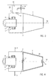
- the Fig. 1 shows a bearing assembly 1, which is arranged in a storage chamber 2.
- the storage chamber 2 comprises a wall 3.
- an oil supply line 4 and an oil return line 5 are shown.
- a rotating shaft is provided with the reference numeral 6.
- an exhaust cone 7 connects to the storage chamber 2, an exhaust cone 7 connects.
- the reference numeral 8 an air seal is shown.
- the structure corresponds to the structures known from the prior art, so that it is possible to dispense with a detailed further description at this point.
- the Fig. 1 shows an embodiment in which a venting takes place through the rear exhaust cone 7.
- This embodiment employs a vent valve 14 disposed on a wall adjacent to the exhaust cone 7, preferably on or above the centerline of the axis of rotation, to limit the amount of gas turbine static condition oil leakage.
- the vent valve 14 vented through a vent tube 17, which extends centrally through the exhaust cone to the environment.
- FIG. 2 and 3 show other embodiments in which the vent valve 14 is vented by the rear support strut 10.
- the support strut 10 should be provided with a double wall for safety reasons.
- venting then takes place ( Fig. 2 ) via a line to an oil separator 11 and the vent 12th
- Venting takes place via an ejector system 9 from the rear support strut 10 into a bypass line 13.
- the Fig. 4 shows a further embodiment in which a cavity in the exhaust cone 7 is used. Venting by means of the vent valve 14 into the inner chamber 18 of the exhaust cone 7. For venting into the environment, a second vent valve 15 is provided.
- This embodiment is based on the principle to form a pressure drop in the inner chamber 18, so that when the pressure in the storage chamber exceeds the sealing air pressure, the vent valve 14 opens at the interface between the storage chamber 2 and the inner chamber 18 and the pressure from the storage chamber in the inner chamber 18 degrades. This requires that the pressure in the inner chamber 18 be lower than the pressure in the storage chamber.
- the second vent valve 15 is provided at the other end of the exhaust cone 7, so that the inner chamber 18 at high altitudes, in which the pressure is lower, than at a speed reduction of the gas turbine during the descent or a shutdown of the gas turbine normal operation at the bottom, is vented.
- This solution requires the use of a logic circuit (regulation or control) for the opening and closing of the vent valves 14 and 15.
- the circuit can operate according to the following conditions: operating condition Bleed valve 14 Bleed valve 15 Rolls of the plane closed closed closed closed Take off (MTO) closed closed Climb (MCL) closed closed closed Cruising flight (MCR) closed open Beginning of sinking open closed fall closed open Approach and landing closed closed closed reverse thrust closed closed Rolls of the plane closed closed closed Switch off open closed closed
- reaction time of the vent valve 14 is shorter than the time which is allowed to reduce the speed of the high pressure compressor of the gas turbine to prevent flow reversal through the seal of the bearing assembly.
Landscapes
- Engineering & Computer Science (AREA)
- Mechanical Engineering (AREA)
- General Engineering & Computer Science (AREA)
- Chemical & Material Sciences (AREA)
- Combustion & Propulsion (AREA)
- Turbine Rotor Nozzle Sealing (AREA)
- Magnetic Bearings And Hydrostatic Bearings (AREA)
Applications Claiming Priority (1)
| Application Number | Priority Date | Filing Date | Title |
|---|---|---|---|
| DE102007058953A DE102007058953A1 (de) | 2007-12-07 | 2007-12-07 | Lagerkammerdrucksystem |
Publications (2)
| Publication Number | Publication Date |
|---|---|
| EP2067963A2 true EP2067963A2 (fr) | 2009-06-10 |
| EP2067963A3 EP2067963A3 (fr) | 2011-08-03 |
Family
ID=40269673
Family Applications (1)
| Application Number | Title | Priority Date | Filing Date |
|---|---|---|---|
| EP08021198A Withdrawn EP2067963A3 (fr) | 2007-12-07 | 2008-12-05 | Système de pression de chambre de stockage |
Country Status (3)
| Country | Link |
|---|---|
| US (1) | US8235647B2 (fr) |
| EP (1) | EP2067963A3 (fr) |
| DE (1) | DE102007058953A1 (fr) |
Cited By (2)
| Publication number | Priority date | Publication date | Assignee | Title |
|---|---|---|---|---|
| EP2336501A3 (fr) * | 2009-12-21 | 2013-12-04 | Rolls-Royce Deutschland Ltd & Co KG | Agencement d'évacuation d'air de ventilation d'huile dans une turbine à gaz |
| EP2336503A3 (fr) * | 2009-12-21 | 2013-12-04 | Rolls-Royce Deutschland Ltd & Co KG | Agencement d'évacuation d'air de ventilation séparé à partir d'un système d'aération des huiles lubrifiantes d'un turboréacteur |
Families Citing this family (18)
| Publication number | Priority date | Publication date | Assignee | Title |
|---|---|---|---|---|
| US8621839B2 (en) * | 2009-09-28 | 2014-01-07 | Pratt & Whitney Canada Corp. | Gas turbine engine breather exhaust oil collector |
| GB201109799D0 (en) * | 2011-06-13 | 2011-07-27 | Rolls Royce Plc | A bearing chamber apparatus |
| US8956106B2 (en) * | 2011-12-20 | 2015-02-17 | General Electric Company | Adaptive eductor system |
| US9080687B2 (en) | 2012-05-24 | 2015-07-14 | Honeywell International Inc. | Pressure and flow altitude compensated shutoff valve |
| DE102012218135B4 (de) * | 2012-10-04 | 2017-07-27 | Rolls-Royce Deutschland Ltd & Co Kg | Lagerkammerentlüftungssystem für ein Flugzeugtriebwerk und Verfahren zum Bereitstellen eines gewünschten Druckverhältnisses an Lagerkammerdichtungen einer luftgedichteten Lagerkammer |
| EP2964911B1 (fr) | 2013-03-04 | 2022-02-23 | Echogen Power Systems LLC | Systèmes de moteur thermique possédant des circuits de dioxyde de carbone supercritique à haute énergie nette |
| GB201412869D0 (en) * | 2014-07-21 | 2014-09-03 | Rolls Royce Plc | Pressure controlled chamber |
| WO2016073252A1 (fr) | 2014-11-03 | 2016-05-12 | Echogen Power Systems, L.L.C. | Gestion de poussée active d'une turbopompe à l'intérieur d'un circuit de circulation de fluide de travail supercritique dans un système de moteur thermique |
| DE102016108068A1 (de) | 2016-05-02 | 2017-11-02 | Rolls-Royce Deutschland Ltd & Co Kg | Turbofantriebwerk und Verfahren zum Abführen von Abblaseluft eines Ölabscheiders in einem Turbofantriebwerk |
| US10450894B2 (en) | 2016-11-28 | 2019-10-22 | United Technologies Corporation | Bearing compartment scavenge control |
| US10502141B2 (en) * | 2017-03-01 | 2019-12-10 | Pratt & Whitney Canada Corp. | Apparatus and method for controlling a pressure differential across a seal of a bearing chamber |
| US11187112B2 (en) | 2018-06-27 | 2021-11-30 | Echogen Power Systems Llc | Systems and methods for generating electricity via a pumped thermal energy storage system |
| US11435120B2 (en) | 2020-05-05 | 2022-09-06 | Echogen Power Systems (Delaware), Inc. | Split expansion heat pump cycle |
| US11629638B2 (en) | 2020-12-09 | 2023-04-18 | Supercritical Storage Company, Inc. | Three reservoir electric thermal energy storage system |
| US12516855B2 (en) | 2022-10-27 | 2026-01-06 | Supercritical Storage Company, Inc. | High-temperature, dual rail heat pump cycle for high performance at high-temperature lift and range |
| US11905841B1 (en) | 2023-02-03 | 2024-02-20 | Rtx Corporation | Buffer air method and system for a bearing compartment |
| AU2024289421A1 (en) | 2023-02-07 | 2025-09-11 | Supercritical Storage Company, Inc. | Waste heat integration into pumped thermal energy storage |
| US20250334078A1 (en) * | 2024-04-26 | 2025-10-30 | Hamilton Sundstrand Corporation | Active control of gearbox case pressure |
Family Cites Families (15)
| Publication number | Priority date | Publication date | Assignee | Title |
|---|---|---|---|---|
| GB509238A (en) | 1937-10-12 | 1939-07-12 | Neil Shaw Muir | Improvements in means for heating liquids, for use in the operation of aircraft and for other purposes |
| FR1429690A (fr) * | 1965-03-31 | 1966-02-25 | Rolls Royce | Ensemble de palier |
| DE2605619C3 (de) | 1976-02-12 | 1978-07-13 | Siemens Ag, 1000 Berlin Und 8000 Muenchen | Schaltungsanordnung zum Erkennen von Fehlern bei einer durch Prüfzeichen gesicherten Übertragung von Datenzeichen |
| US4284174A (en) | 1979-04-18 | 1981-08-18 | Avco Corporation | Emergency oil/mist system |
| DE2940643A1 (de) * | 1979-10-06 | 1981-04-16 | Klöckner-Humboldt-Deutz AG, 5000 Köln | Einrichtung zum an- bzw. aufheizen von maschinen |
| GB2111607B (en) * | 1981-12-08 | 1985-09-18 | Rolls Royce | Bearing chamber pressurisation system for a machine |
| US4433539A (en) * | 1982-05-13 | 1984-02-28 | United Technologies Corporation | Means for controlling air scavenge pressure in the bearing compartment of gas turbines |
| US4441311A (en) * | 1982-05-13 | 1984-04-10 | United Technologies Corporation | Means for controlling the air scavenge pressure in the bearing compartment of a gas turbine engine |
| JPH0667517B2 (ja) | 1986-01-29 | 1994-08-31 | 株式会社荏原製作所 | 有機性水溶液のメタン発酵法 |
| DE3605619A1 (de) | 1986-02-21 | 1987-08-27 | Mtu Muenchen Gmbh | Stroemungsmaschine mit versorgungseinrichtung fuer schmiermittel |
| US20030097872A1 (en) * | 2001-11-29 | 2003-05-29 | Granitz Charles Robert | System for reducing oil consumption in gas turbine engines |
| GB2391959B (en) * | 2002-08-13 | 2006-01-04 | Rolls Royce Plc | Vents for bearing chambers |
| US7836675B2 (en) * | 2006-02-21 | 2010-11-23 | General Electric Company | Supercore sump vent pressure control |
| US7451753B2 (en) | 2006-04-21 | 2008-11-18 | Pratt & Whitney Canada Corp. | Pre-heating of a liquid in an aircraft reservoir |
| DE102007022922A1 (de) | 2007-05-14 | 2009-04-02 | Rolls-Royce Deutschland Ltd & Co Kg | Ölabscheider für eine Fluggasturbine mit verbessertem Ventleitungsanschluss |
-
2007
- 2007-12-07 DE DE102007058953A patent/DE102007058953A1/de not_active Withdrawn
-
2008
- 2008-12-05 EP EP08021198A patent/EP2067963A3/fr not_active Withdrawn
- 2008-12-08 US US12/314,329 patent/US8235647B2/en active Active
Cited By (4)
| Publication number | Priority date | Publication date | Assignee | Title |
|---|---|---|---|---|
| EP2336501A3 (fr) * | 2009-12-21 | 2013-12-04 | Rolls-Royce Deutschland Ltd & Co KG | Agencement d'évacuation d'air de ventilation d'huile dans une turbine à gaz |
| EP2336503A3 (fr) * | 2009-12-21 | 2013-12-04 | Rolls-Royce Deutschland Ltd & Co KG | Agencement d'évacuation d'air de ventilation séparé à partir d'un système d'aération des huiles lubrifiantes d'un turboréacteur |
| US8640436B2 (en) | 2009-12-21 | 2014-02-04 | Rolls-Royce Deutschland Ltd & Co Kg | Arrangement for the discharge of exhaust air separated from the lubricating oil de-aeration system of a gas-turbine engine |
| US8826637B2 (en) | 2009-12-21 | 2014-09-09 | Rolls-Royce Deutschland Ltd & Co Kg | Arrangement for the discharge of oil-venting air on a gas-turbine engine |
Also Published As
| Publication number | Publication date |
|---|---|
| DE102007058953A1 (de) | 2009-06-10 |
| EP2067963A3 (fr) | 2011-08-03 |
| US20100143094A1 (en) | 2010-06-10 |
| US8235647B2 (en) | 2012-08-07 |
Similar Documents
| Publication | Publication Date | Title |
|---|---|---|
| EP2067963A2 (fr) | Système de pression de chambre de stockage | |
| DE3015650C2 (de) | Notschmiereinrichtung für Gasturbinenanlagen | |
| DE102016105302B4 (de) | Steuerstromregelventil, insbesondere für Spiralverdichter in Fahrzeugklimaanlagen oder Wärmepumpen | |
| DE2512569A1 (de) | Klimaanlage, insbesondere fuer kraftfahrzeuge | |
| DE2708900A1 (de) | Regelsystem fuer schraubenverdichter | |
| EP2005002B1 (fr) | Compresseur à vis comportant une soupape de délestage | |
| DE60307662T2 (de) | Kompressor mit leistungsregelung | |
| DE1503586A1 (de) | Fluessigkeitsringpumpe und Verfahren zum Abdichten von Fluessigkeitsringpumpen | |
| EP1134467B1 (fr) | Installation de soupape dans un système de refrigération | |
| DE102015100380A1 (de) | Variable Ansaugvorrichtung für einen A/C-Verdichter zur Verbesserung der NVH-Eigenschaften durch Veränderung des Ansaugeinlassströmungsbereichs | |
| EP2065555B1 (fr) | Procédé de fonctionnement d'un dispositif de compresseur et dispositif de compresseur correspondant | |
| DE2034188C3 (de) | Schmiervorrichtung fur Gastur binentriebwerke | |
| DE3150033A1 (de) | Vakuumpumpe mit einem saugstutzen-ventil und betriebsverfahren dafuer | |
| DE102009053133A1 (de) | Kolbenverdichter mit Leerlaufventil | |
| DE102009023824A1 (de) | Thermostat-Druckbegrenzungsventil, selbstregelnde Fluidpumpe und Schmierölkreislauf einer Brennkraftmaschine | |
| EP3169902B1 (fr) | Compresseur a vis | |
| DE102016115360A1 (de) | Überströmventil zum zumindest teilweisen Verschließen und Öffnen eines Fluidleitungssystems | |
| DE10261120A1 (de) | Membran-Druckregelventil | |
| EP1541803A2 (fr) | Arrangement de soulagement des paliers dans une turbine à gaz | |
| DE691285C (de) | Belueftungseinrichtung fuer gegenueber der Aussenluft unter UEberdruck stehende Hoehenkammern in Luftfahrzeugen | |
| EP2006584A1 (fr) | Dispositif amortisseur destinée à la conduite de gaz de fuite dans un système d'évacuation et système de gaz d'étanchéité | |
| EP0966611B1 (fr) | Pompe avec garniture d'etancheite | |
| DE102018211924A1 (de) | Kraftstofffördereinrichtung für kryogene Kraftstoffe | |
| DE112017006334T5 (de) | Gasturbinenmotor | |
| DD271546A1 (de) | Anordnung zur wellenabdichtung an oelueberfluteten schraubenverdichtern |
Legal Events
| Date | Code | Title | Description |
|---|---|---|---|
| PUAI | Public reference made under article 153(3) epc to a published international application that has entered the european phase |
Free format text: ORIGINAL CODE: 0009012 |
|
| AK | Designated contracting states |
Kind code of ref document: A2 Designated state(s): AT BE BG CH CY CZ DE DK EE ES FI FR GB GR HR HU IE IS IT LI LT LU LV MC MT NL NO PL PT RO SE SI SK TR |
|
| AX | Request for extension of the european patent |
Extension state: AL BA MK RS |
|
| PUAL | Search report despatched |
Free format text: ORIGINAL CODE: 0009013 |
|
| AK | Designated contracting states |
Kind code of ref document: A3 Designated state(s): AT BE BG CH CY CZ DE DK EE ES FI FR GB GR HR HU IE IS IT LI LT LU LV MC MT NL NO PL PT RO SE SI SK TR |
|
| AX | Request for extension of the european patent |
Extension state: AL BA MK RS |
|
| RIC1 | Information provided on ipc code assigned before grant |
Ipc: F01D 25/18 20060101ALI20110624BHEP Ipc: F01D 25/16 20060101ALI20110624BHEP Ipc: F02C 7/06 20060101AFI20090129BHEP |
|
| AKY | No designation fees paid | ||
| REG | Reference to a national code |
Ref country code: DE Ref legal event code: R108 Effective date: 20120411 |
|
| STAA | Information on the status of an ep patent application or granted ep patent |
Free format text: STATUS: THE APPLICATION IS DEEMED TO BE WITHDRAWN |
|
| 18D | Application deemed to be withdrawn |
Effective date: 20120204 |