EP2068014A1 - Verrouillage pour assemblage vissé - Google Patents
Verrouillage pour assemblage vissé Download PDFInfo
- Publication number
- EP2068014A1 EP2068014A1 EP07023776A EP07023776A EP2068014A1 EP 2068014 A1 EP2068014 A1 EP 2068014A1 EP 07023776 A EP07023776 A EP 07023776A EP 07023776 A EP07023776 A EP 07023776A EP 2068014 A1 EP2068014 A1 EP 2068014A1
- Authority
- EP
- European Patent Office
- Prior art keywords
- channel
- nut
- section
- thread
- blocking element
- Prior art date
- Legal status (The legal status is an assumption and is not a legal conclusion. Google has not performed a legal analysis and makes no representation as to the accuracy of the status listed.)
- Withdrawn
Links
- 230000000903 blocking effect Effects 0.000 claims abstract description 17
- RYGMFSIKBFXOCR-UHFFFAOYSA-N Copper Chemical compound [Cu] RYGMFSIKBFXOCR-UHFFFAOYSA-N 0.000 claims description 3
- 229910052802 copper Inorganic materials 0.000 claims description 3
- 239000010949 copper Substances 0.000 claims description 3
- 239000000463 material Substances 0.000 claims description 3
- 229910001220 stainless steel Inorganic materials 0.000 claims description 3
- 239000010935 stainless steel Substances 0.000 claims description 3
- 239000000853 adhesive Substances 0.000 description 1
- 230000001070 adhesive effect Effects 0.000 description 1
- 230000004888 barrier function Effects 0.000 description 1
- 150000001875 compounds Chemical class 0.000 description 1
- 238000006073 displacement reaction Methods 0.000 description 1
Images
Classifications
-
- F—MECHANICAL ENGINEERING; LIGHTING; HEATING; WEAPONS; BLASTING
- F16—ENGINEERING ELEMENTS AND UNITS; GENERAL MEASURES FOR PRODUCING AND MAINTAINING EFFECTIVE FUNCTIONING OF MACHINES OR INSTALLATIONS; THERMAL INSULATION IN GENERAL
- F16B—DEVICES FOR FASTENING OR SECURING CONSTRUCTIONAL ELEMENTS OR MACHINE PARTS TOGETHER, e.g. NAILS, BOLTS, CIRCLIPS, CLAMPS, CLIPS OR WEDGES; JOINTS OR JOINTING
- F16B39/00—Locking of screws, bolts or nuts
- F16B39/22—Locking of screws, bolts or nuts in which the locking takes place during screwing down or tightening
- F16B39/28—Locking of screws, bolts or nuts in which the locking takes place during screwing down or tightening by special members on, or shape of, the nut or bolt
- F16B39/34—Locking by deformable inserts or like parts
Definitions
- the invention relates to a device for securing a screw connection.
- a screw connection normally comprises a screw, an internal thread carrier such as a nut and a component to be fastened. If such a screw connection - in particular by vibrations - dynamically stressed, this can lead to the compound automatically loosening by turning the screw or the internal thread carrier. As a result, the component is braced with a reduced clamping force, which can lead to failure of the screw connection.
- Such a ratchet screw has under its screw head on a radially extending profile, which is formed - such as pie-like - slightly curved, inclined planes. Each inclined plane has a slight pitch in the tightening direction of the screw, whereas it has a high pitch in the loosening direction.
- the screw can be screwed in with little effort, with the profile impressed into the surface of a component to be screwed. The steep edges of the profile then cause a high resistance against loosening of the screw and thus secure the screw or the screw connection.
- Another conventional screw lock provides to secure the nut with a pair of wedge discs clamped under the nut, so-called "Nord-Lock washers".
- the wedge discs have on the outer surfaces facing away from each other radial ribs, which in the tightening of the nut on the one hand in the surface of the nut and on the other hand emboss in the surface of the component to be screwed. This results in a positive connection between the nut and wedge disk or between the component and wedge disk.
- the wedge disks are provided with interlocking inclined planes - "wedges". A rotation of the nut now causes the two wedge slices to move against each other along the inclined planes. Since the angle of the inclined planes is greater than the thread pitch of the nut, the clamping force of the screw connection is increased by the displacement of the wedge discs and thus the screw connection is secured.
- the invention has for its object to provide a particularly suitable device for securing a screw connection.
- the nut is provided with a continuous channel, which opens with a first end to an underside of the nut. This underside of the nut is facing in a mounting position a surface of a component to be screwed. With a second end of the channel opens at an inner thread of the nut.
- the blocking element comprises a hard section and a comparatively soft section.
- the locking member In a preassembled state, the locking member is seated in the channel so that it protrudes with a free end of the hard portion on the underside of the nut from the channel, whereas the soft portion is completely received in the channel.
- the blocking element is displaceable in the coaxial direction in the channel in such a way that a free end of the soft portion protrudes into the thread when the free end of the hard portion with the bottom of the Nut is flush.
- the blocking element as a whole is thus in the raw state, in particular longer than the channel.
- the hard section of the blocking element projecting from the underside is first pushed into the channel of the nut by the surface of the component to be screwed.
- the hard portion in this case pushes the soft section in front of it, so that the soft portion of the locking element is pushed out of the channel at the second end of the channel.
- the free end of the soft section is thereby pressed into the thread and thus against an external thread of a screw screwed into this.
- the free end of the soft section is squeezed into the thread clearance between the nut and screw, thus locking the nut against the screw.
- the "hard” portion of the locking element is expediently about as hard or even harder as the nut and the component to be screwed.
- the “soft” portion of the locking element is formed of a material which is soft both with respect to the hard portion, and with respect to the component to be screwed and the screw.
- the locking element on its hard portion so hard that it is impressed in tightened nut in the surface of the component to be screwed.
- the blocking element is soft enough that it is squeezed into the thread of the screw when the nut is tightened.
- the blocking element is pin-shaped, wherein its cross-sectional shape is adapted to the cross-sectional shape of the channel, so that the locking element rests accurately in the channel.
- the locking element is held in particular by a surmountable frictional engagement in the channel, so that an automatic falling out of the locking element from the nut under storage and transport conditions is prevented.
- the pin can also be glued in addition in the pre-assembled state, this adhesive connection is designed such that it is broken when tightening the nut.
- the channel cross section is round.
- the channel can be conveniently introduced through a simple bore in the nut.
- the nut is provided with three similar channels, which are distributed uniformly over the circumference of the nut, each channel being provided with a blocking element.
- the screw connection is already relatively well secured by three locking elements.
- the stability of the nut is still relatively little affected by the introduction of three channels.
- the channel has a small cross-section compared to the diameter of the thread.
- the channel opens at the bottom of the nut approximately centrally between the edge of the threaded bushing and the (middle) outer periphery. Additionally or alternatively, the channel also opens in the thread approximately at a medium axial height between the bottom and an opposite top of the nut. Again in addition or alternatively has become an inclination of the channel of about 20 ° with respect to an axis of the thread proved to be advantageous.
- the hard portion of the barrier member is made of stainless steel.
- the soft section is preferably made of copper or plastic. Through these materials, the function of the blocking element, as described above, safely guaranteed.
- the terms "hard” and “soft” are generally to be understood in the present application as referring to the other portion, unless otherwise indicated by context.
- the portion 10 of the locking pin 3 is thus harder than the portion 11, or vice versa: the portion 11 of the locking pin 3 is thus softer than the portion 10th
- the hard portion and the soft portion of the locking element are fixed, in particular cohesively, connected to each other, so that the locking element is made in one piece.
- the pre-assembly of the nut is made easier with locking elements expediently.
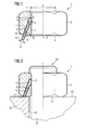
- FIG. 1 shows a side view of a device 1 for screw locking.
- the device 1 comprises a screw nut 2, the left half of which is shown in the illustration and a blocking element in the form of a locking pin 3.
- the nut 2 comprises a continuous oblique channel in the form of a bore 4 with a diameter d, an inner thread 5 with a diameter D and a bottom 6.
- a radially-axially mounted partial cross-sectional area 7 of the nut 2 is shown.
- the continuous, oblique bore 4 opens with a first end 8 at the bottom 6 and with a second end 9 on the thread 5.
- the bore 4 is positioned so that the first end 8 at the bottom 6 approximately radially in the middle opposite to an axis A of the thread 5, the bore 4 is inclined at an angle ⁇ of 20 °, whereby relative to the bottom 6 a slope in gives an angle ⁇ of 70 °. From the illustration it is also clear that the diameter d of the bore 4 is small in relation to the diameter D of the thread 5.
- the cylindrical locking pin 3 comprises hard section 10 made of stainless steel and a soft section 11 made of copper.
- the locking pin 3 is precisely inserted into the bore 4, that it protrudes with a first free end 12 at the bottom 6 of the nut 2 from the bore 4, whereas it is flush with a second free end 13 approximately with the thread 5, thus thus completely absorbed in the bore 4.
- the locking pin 3 is held captive in the bore 4 by frictional engagement. However, this frictional engagement can be overcome by exerting pressure on the protruding free end 12, so that the locking pin 3 can be displaced in the bore 4.
- FIG. 2 is shown in partially sectioned side view of a screw connection 20 which is secured with the device 1 according to the invention.
- the screw connection 20 comprises the locking nut 3 provided with the screw nut 2 and a partially shown screw 21 and only partially shown component 22, which is braced by the nut 2 and the screw 21.
- the component 22 is provided with a bore into which the screw 21 is introduced.
- the nut 2 is now mounted on the screw 21 so that it points with its bottom 6 in the direction of an adjacent surface 23 of the component 22.
Landscapes
- Engineering & Computer Science (AREA)
- General Engineering & Computer Science (AREA)
- Mechanical Engineering (AREA)
- Bolts, Nuts, And Washers (AREA)
Priority Applications (1)
| Application Number | Priority Date | Filing Date | Title |
|---|---|---|---|
| EP07023776A EP2068014A1 (fr) | 2007-12-07 | 2007-12-07 | Verrouillage pour assemblage vissé |
Applications Claiming Priority (1)
| Application Number | Priority Date | Filing Date | Title |
|---|---|---|---|
| EP07023776A EP2068014A1 (fr) | 2007-12-07 | 2007-12-07 | Verrouillage pour assemblage vissé |
Publications (1)
| Publication Number | Publication Date |
|---|---|
| EP2068014A1 true EP2068014A1 (fr) | 2009-06-10 |
Family
ID=39326990
Family Applications (1)
| Application Number | Title | Priority Date | Filing Date |
|---|---|---|---|
| EP07023776A Withdrawn EP2068014A1 (fr) | 2007-12-07 | 2007-12-07 | Verrouillage pour assemblage vissé |
Country Status (1)
| Country | Link |
|---|---|
| EP (1) | EP2068014A1 (fr) |
Cited By (3)
| Publication number | Priority date | Publication date | Assignee | Title |
|---|---|---|---|---|
| CN109268378A (zh) * | 2018-11-28 | 2019-01-25 | 海盐县华昇汽车配件有限公司 | 一种带齿法兰防松螺母 |
| DE102020121191A1 (de) | 2020-08-12 | 2022-02-17 | Neugart Gmbh | Spannmittel, Getriebe sowie Verwendung eines Zuführkanals und Verfahren zur Einstellung eines Lagerspiels eines Getriebes |
| CN116816796A (zh) * | 2023-08-18 | 2023-09-29 | 扬州三劦紧固件有限公司 | 一种止退连接螺栓组件 |
Citations (4)
| Publication number | Priority date | Publication date | Assignee | Title |
|---|---|---|---|---|
| US1051246A (en) * | 1912-03-09 | 1913-01-21 | David S Marple | Nut-lock. |
| US1565250A (en) * | 1925-08-22 | 1925-12-15 | Paul I Bible | Nut lock |
| SU1518577A1 (ru) * | 1987-10-12 | 1989-10-30 | Предприятие П/Я Г-4213 | Самоконтр ща с гайка |
| US5360302A (en) * | 1993-07-26 | 1994-11-01 | California Institute Of Technology | Internal impacted screw-locking pellet |
-
2007
- 2007-12-07 EP EP07023776A patent/EP2068014A1/fr not_active Withdrawn
Patent Citations (4)
| Publication number | Priority date | Publication date | Assignee | Title |
|---|---|---|---|---|
| US1051246A (en) * | 1912-03-09 | 1913-01-21 | David S Marple | Nut-lock. |
| US1565250A (en) * | 1925-08-22 | 1925-12-15 | Paul I Bible | Nut lock |
| SU1518577A1 (ru) * | 1987-10-12 | 1989-10-30 | Предприятие П/Я Г-4213 | Самоконтр ща с гайка |
| US5360302A (en) * | 1993-07-26 | 1994-11-01 | California Institute Of Technology | Internal impacted screw-locking pellet |
Cited By (3)
| Publication number | Priority date | Publication date | Assignee | Title |
|---|---|---|---|---|
| CN109268378A (zh) * | 2018-11-28 | 2019-01-25 | 海盐县华昇汽车配件有限公司 | 一种带齿法兰防松螺母 |
| DE102020121191A1 (de) | 2020-08-12 | 2022-02-17 | Neugart Gmbh | Spannmittel, Getriebe sowie Verwendung eines Zuführkanals und Verfahren zur Einstellung eines Lagerspiels eines Getriebes |
| CN116816796A (zh) * | 2023-08-18 | 2023-09-29 | 扬州三劦紧固件有限公司 | 一种止退连接螺栓组件 |
Similar Documents
| Publication | Publication Date | Title |
|---|---|---|
| EP2318723B1 (fr) | Agencement de fixation avec compensation des tolerances | |
| EP2325502B1 (fr) | Agencement et procédé pour relier un accessoire avec une table d'opération | |
| DE69712726T2 (de) | Sicherungsmutter | |
| EP0193020B1 (fr) | Dispositif d'outillage avec tête interchangeable | |
| DE102005017690A1 (de) | Kabeldurchführung | |
| EP0275441B1 (fr) | Dispositif de serrage | |
| WO2016165823A1 (fr) | Dispositif de fixation | |
| EP1855018A2 (fr) | Arrêt de vis | |
| EP3895872A1 (fr) | Dispositif de chauffage électrique extensible | |
| DE102019111237B4 (de) | Zweiteilige Schraubenmutter mit hoher Andrückkraft | |
| DE2020782A1 (de) | Sicherungsmutter | |
| EP2068014A1 (fr) | Verrouillage pour assemblage vissé | |
| DE68926336T2 (de) | Bolzeneinrichtung | |
| EP0846908A1 (fr) | Connection entre tube et composant. | |
| EP0062271A1 (fr) | Dispositif de fixation | |
| WO1994018470A1 (fr) | Dispositif de fixation pour freins a disques | |
| DE2234353A1 (de) | Federnde klammer | |
| DE4231339C2 (de) | Vorrichtung zum Paßzentrieren und Paßverbinden von Teilen | |
| EP1612432B1 (fr) | Dispositif de fixation pour habillage et méthode de fixation | |
| DE29807967U1 (de) | Vorrichtung zum Verbinden von Bauteilen | |
| DE102019114186A1 (de) | Bolzenverbindung | |
| DE102021103968B3 (de) | Montage-Einheit mit zumindest einer Montageschiene sowie wenigstens einer Halteklammer | |
| EP0905425B1 (fr) | Dispositif de fixation | |
| DE9305188U1 (de) | Schnellspannvorrichtung für Stichsägeblätter | |
| DE29817010U1 (de) | Verschraubungsteil |
Legal Events
| Date | Code | Title | Description |
|---|---|---|---|
| PUAI | Public reference made under article 153(3) epc to a published international application that has entered the european phase |
Free format text: ORIGINAL CODE: 0009012 |
|
| AK | Designated contracting states |
Kind code of ref document: A1 Designated state(s): AT BE BG CH CY CZ DE DK EE ES FI FR GB GR HU IE IS IT LI LT LU LV MC MT NL PL PT RO SE SI SK TR |
|
| AX | Request for extension of the european patent |
Extension state: AL BA HR MK RS |
|
| AKX | Designation fees paid | ||
| STAA | Information on the status of an ep patent application or granted ep patent |
Free format text: STATUS: THE APPLICATION IS DEEMED TO BE WITHDRAWN |
|
| 18D | Application deemed to be withdrawn |
Effective date: 20091211 |
|
| REG | Reference to a national code |
Ref country code: DE Ref legal event code: 8566 |