EP2068069B1 - System und Verfahren zur Beleuchtung von frei schwebenden Körpern - Google Patents
System und Verfahren zur Beleuchtung von frei schwebenden Körpern Download PDFInfo
- Publication number
- EP2068069B1 EP2068069B1 EP08445028A EP08445028A EP2068069B1 EP 2068069 B1 EP2068069 B1 EP 2068069B1 EP 08445028 A EP08445028 A EP 08445028A EP 08445028 A EP08445028 A EP 08445028A EP 2068069 B1 EP2068069 B1 EP 2068069B1
- Authority
- EP
- European Patent Office
- Prior art keywords
- light
- levitating
- aperture
- base
- light source
- Prior art date
- Legal status (The legal status is an assumption and is not a legal conclusion. Google has not performed a legal analysis and makes no representation as to the accuracy of the status listed.)
- Not-in-force
Links
- 238000005286 illumination Methods 0.000 title description 21
- 238000000034 method Methods 0.000 title description 8
- 230000000007 visual effect Effects 0.000 claims description 16
- 239000000463 material Substances 0.000 claims description 7
- 230000003287 optical effect Effects 0.000 claims description 3
- 230000000694 effects Effects 0.000 description 11
- 239000000835 fiber Substances 0.000 description 8
- 238000005339 levitation Methods 0.000 description 4
- 239000011324 bead Substances 0.000 description 2
- 239000010432 diamond Substances 0.000 description 2
- 229910003460 diamond Inorganic materials 0.000 description 2
- 239000011521 glass Substances 0.000 description 2
- 230000004048 modification Effects 0.000 description 2
- 238000012986 modification Methods 0.000 description 2
- 230000015572 biosynthetic process Effects 0.000 description 1
- 239000003086 colorant Substances 0.000 description 1
- 239000004020 conductor Substances 0.000 description 1
- 230000002708 enhancing effect Effects 0.000 description 1
- 239000000446 fuel Substances 0.000 description 1
- 230000006870 function Effects 0.000 description 1
- 239000010437 gem Substances 0.000 description 1
- 229910001751 gemstone Inorganic materials 0.000 description 1
- 230000004313 glare Effects 0.000 description 1
- 230000001939 inductive effect Effects 0.000 description 1
- 230000003993 interaction Effects 0.000 description 1
- 230000008520 organization Effects 0.000 description 1
- 238000005192 partition Methods 0.000 description 1
- 230000001737 promoting effect Effects 0.000 description 1
- 230000035807 sensation Effects 0.000 description 1
- 239000000126 substance Substances 0.000 description 1
- 238000001429 visible spectrum Methods 0.000 description 1
Images




Classifications
-
- G—PHYSICS
- G09—EDUCATION; CRYPTOGRAPHY; DISPLAY; ADVERTISING; SEALS
- G09F—DISPLAYING; ADVERTISING; SIGNS; LABELS OR NAME-PLATES; SEALS
- G09F19/00—Advertising or display means not otherwise provided for
- G09F19/02—Advertising or display means not otherwise provided for incorporating moving display members
-
- F—MECHANICAL ENGINEERING; LIGHTING; HEATING; WEAPONS; BLASTING
- F21—LIGHTING
- F21S—NON-PORTABLE LIGHTING DEVICES; SYSTEMS THEREOF; VEHICLE LIGHTING DEVICES SPECIALLY ADAPTED FOR VEHICLE EXTERIORS
- F21S10/00—Lighting devices or systems producing a varying lighting effect
- F21S10/005—Lighting devices or systems producing a varying lighting effect using light guides
-
- B—PERFORMING OPERATIONS; TRANSPORTING
- B44—DECORATIVE ARTS
- B44C—PRODUCING DECORATIVE EFFECTS; MOSAICS; TARSIA WORK; PAPERHANGING
- B44C1/00—Processes, not specifically provided for elsewhere, for producing decorative surface effects
-
- F—MECHANICAL ENGINEERING; LIGHTING; HEATING; WEAPONS; BLASTING
- F21—LIGHTING
- F21S—NON-PORTABLE LIGHTING DEVICES; SYSTEMS THEREOF; VEHICLE LIGHTING DEVICES SPECIALLY ADAPTED FOR VEHICLE EXTERIORS
- F21S10/00—Lighting devices or systems producing a varying lighting effect
-
- F—MECHANICAL ENGINEERING; LIGHTING; HEATING; WEAPONS; BLASTING
- F21—LIGHTING
- F21S—NON-PORTABLE LIGHTING DEVICES; SYSTEMS THEREOF; VEHICLE LIGHTING DEVICES SPECIALLY ADAPTED FOR VEHICLE EXTERIORS
- F21S8/00—Lighting devices intended for fixed installation
-
- F—MECHANICAL ENGINEERING; LIGHTING; HEATING; WEAPONS; BLASTING
- F21—LIGHTING
- F21V—FUNCTIONAL FEATURES OR DETAILS OF LIGHTING DEVICES OR SYSTEMS THEREOF; STRUCTURAL COMBINATIONS OF LIGHTING DEVICES WITH OTHER ARTICLES, NOT OTHERWISE PROVIDED FOR
- F21V17/00—Fastening of component parts of lighting devices, e.g. shades, globes, refractors, reflectors, filters, screens, grids or protective cages
- F21V17/10—Fastening of component parts of lighting devices, e.g. shades, globes, refractors, reflectors, filters, screens, grids or protective cages characterised by specific fastening means or way of fastening
- F21V17/105—Fastening of component parts of lighting devices, e.g. shades, globes, refractors, reflectors, filters, screens, grids or protective cages characterised by specific fastening means or way of fastening using magnets
-
- F—MECHANICAL ENGINEERING; LIGHTING; HEATING; WEAPONS; BLASTING
- F21—LIGHTING
- F21V—FUNCTIONAL FEATURES OR DETAILS OF LIGHTING DEVICES OR SYSTEMS THEREOF; STRUCTURAL COMBINATIONS OF LIGHTING DEVICES WITH OTHER ARTICLES, NOT OTHERWISE PROVIDED FOR
- F21V21/00—Supporting, suspending, or attaching arrangements for lighting devices; Hand grips
- F21V21/08—Devices for easy attachment to any desired place, e.g. clip, clamp, magnet
- F21V21/096—Magnetic devices
-
- F—MECHANICAL ENGINEERING; LIGHTING; HEATING; WEAPONS; BLASTING
- F21—LIGHTING
- F21V—FUNCTIONAL FEATURES OR DETAILS OF LIGHTING DEVICES OR SYSTEMS THEREOF; STRUCTURAL COMBINATIONS OF LIGHTING DEVICES WITH OTHER ARTICLES, NOT OTHERWISE PROVIDED FOR
- F21V23/00—Arrangement of electric circuit elements in or on lighting devices
- F21V23/02—Arrangement of electric circuit elements in or on lighting devices the elements being transformers, impedances or power supply units, e.g. a transformer with a rectifier
-
- F—MECHANICAL ENGINEERING; LIGHTING; HEATING; WEAPONS; BLASTING
- F21—LIGHTING
- F21V—FUNCTIONAL FEATURES OR DETAILS OF LIGHTING DEVICES OR SYSTEMS THEREOF; STRUCTURAL COMBINATIONS OF LIGHTING DEVICES WITH OTHER ARTICLES, NOT OTHERWISE PROVIDED FOR
- F21V33/00—Structural combinations of lighting devices with other articles, not otherwise provided for
- F21V33/0004—Personal or domestic articles
- F21V33/0024—Household or table equipment
- F21V33/0028—Decorative household equipment, e.g. plant holders or food dummies
-
- F—MECHANICAL ENGINEERING; LIGHTING; HEATING; WEAPONS; BLASTING
- F21—LIGHTING
- F21V—FUNCTIONAL FEATURES OR DETAILS OF LIGHTING DEVICES OR SYSTEMS THEREOF; STRUCTURAL COMBINATIONS OF LIGHTING DEVICES WITH OTHER ARTICLES, NOT OTHERWISE PROVIDED FOR
- F21V7/00—Reflectors for light sources
- F21V7/0091—Reflectors for light sources using total internal reflection
-
- H—ELECTRICITY
- H02—GENERATION; CONVERSION OR DISTRIBUTION OF ELECTRIC POWER
- H02N—ELECTRIC MACHINES NOT OTHERWISE PROVIDED FOR
- H02N15/00—Holding or levitation devices using magnetic attraction or repulsion, not otherwise provided for
-
- F—MECHANICAL ENGINEERING; LIGHTING; HEATING; WEAPONS; BLASTING
- F21—LIGHTING
- F21W—INDEXING SCHEME ASSOCIATED WITH SUBCLASSES F21K, F21L, F21S and F21V, RELATING TO USES OR APPLICATIONS OF LIGHTING DEVICES OR SYSTEMS
- F21W2121/00—Use or application of lighting devices or systems for decorative purposes, not provided for in codes F21W2102/00 – F21W2107/00
-
- F—MECHANICAL ENGINEERING; LIGHTING; HEATING; WEAPONS; BLASTING
- F21—LIGHTING
- F21W—INDEXING SCHEME ASSOCIATED WITH SUBCLASSES F21K, F21L, F21S and F21V, RELATING TO USES OR APPLICATIONS OF LIGHTING DEVICES OR SYSTEMS
- F21W2131/00—Use or application of lighting devices or systems not provided for in codes F21W2102/00-F21W2121/00
- F21W2131/10—Outdoor lighting
- F21W2131/103—Outdoor lighting of streets or roads
-
- F—MECHANICAL ENGINEERING; LIGHTING; HEATING; WEAPONS; BLASTING
- F21—LIGHTING
- F21W—INDEXING SCHEME ASSOCIATED WITH SUBCLASSES F21K, F21L, F21S and F21V, RELATING TO USES OR APPLICATIONS OF LIGHTING DEVICES OR SYSTEMS
- F21W2131/00—Use or application of lighting devices or systems not provided for in codes F21W2102/00-F21W2121/00
- F21W2131/10—Outdoor lighting
- F21W2131/109—Outdoor lighting of gardens
-
- Y—GENERAL TAGGING OF NEW TECHNOLOGICAL DEVELOPMENTS; GENERAL TAGGING OF CROSS-SECTIONAL TECHNOLOGIES SPANNING OVER SEVERAL SECTIONS OF THE IPC; TECHNICAL SUBJECTS COVERED BY FORMER USPC CROSS-REFERENCE ART COLLECTIONS [XRACs] AND DIGESTS
- Y10—TECHNICAL SUBJECTS COVERED BY FORMER USPC
- Y10S—TECHNICAL SUBJECTS COVERED BY FORMER USPC CROSS-REFERENCE ART COLLECTIONS [XRACs] AND DIGESTS
- Y10S362/00—Illumination
- Y10S362/806—Ornamental or decorative
Definitions
- This invention is generally related to decorative levitating objects, and, more particularly, is related to systems and methods for lighting levitating objects.
- a stationary body may have a first magnet and a levitating body may include a secondary magnet, where the magnets are configured to repulse each other to cause the levitating body to float over the stationary body.
- the stationary body may include a light source to illuminate the levitating body.
- a system for illuminating a levitating body, the system may include a base that has a light source; and a body that levitates over the base.
- the levitating body may have a bottom surface and an upper surface. The bottom surface may have at least one aperture to receive light from the stationary body.
- the levitating body may have internal transmissive surfaces to reflect and scatter the light throughout the levitating body to produce visual decorative displays.
- Alternative embodiments may include a levitating body that tapers from the bottom surface toward the upper surface so as to enable collection of light at a point at the upper surface, such as an apex.
- Another embodiment may include a base that has some magnetic properties and includes a light source and a levitating body that has some magnetic properties configured to interact with the magnetic properties of the base to enable the body to levitate over the base.
- the levitating body may have transmissive surfaces for receiving and reflecting the light throughout the body to produce visual decorating displays.
- Another embodiment may include a base that has a transmitting energy source and a levitating body floating over the base.
- the body includes a light source powered by the transmitted energy, and the body may have transmissive surfaces for reflecting and scattering the light to produce visual decorative displays.
- a further embodiment may include a method for illuminating a floating body, the method comprising the steps of providing a base, providing a light source attached the light source to the base, providing a floating body that has transmissive surfaces, transmitting the light inside the floating body, and transmitting and scattering the light by the transmissive surfaces to generate visual display effects.
- FIG. 1A is a side view of an embodiment of the present invention showing a system for illumination of a levitating body, the system may include a magnetic system that includes a base with a base magnet and a levitating magnet associated with a generally pyramidal levitating structure;
- FIG. 1B is a top view of the base of FIG. 1A ;
- FIG. 2 is a side view of another alternative embodiment of the levitating structure, the levitating structure having a globular light dispersing portion associated with an aperture;
- FIG. 4 is a side view showing an additional alternative embodiment of the levitating structure having a generally spherical light dispersing portion housed within a generally hollow light transmitting container;
- FIG. 7A and FIG. 7B are side views of an additional alternative embodiment of the levitating structure having an ellipsoid light dispersing portion housed within a central portion of a generally pyramidal form;
- FIG. 8A, FIG. 8B, and FIG. 8C show side views of additional alternative embodiments of the levitating structure having a generally pyramidal form and having, respectively, along one or more walls, elongated apertures or slits, decorative round apertures, and alphabetic letter characters;
- FIG. 9 is a side view showing a further alternative embodiment of the levitating structure, the levitating structure having light transmitting strands and/or fiber optic fibers;
- FIG. 10 is side view of an alternative embodiment of the levitating structure, the levitating structure having a generally bottle shaped form and light transmitting strands and/or fiber optic fibers;
- FIG. 11A and FIG. 11B are side views of further alternative levitating structures having a generally pyramidal form and having, respectively, a mirrored reflective surface and an inverted cup shaped translucent hollow structure;
- FIG. 12 is a side view of an alternative embodiment of the present invention showing a system for illumination of a levitating body, the system including a generally cubical levitating structure having a wireless light source;
- FIG. 14 is a side view of an alternative embodiment of the present invention showing a system for illumination of a levitating body, the system including a generally spherical levitating structure having luminous rods extending from the spherical portion;
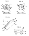
- FIG. 15A and FIG, 15B show perspective and side views, respectively, of an alternative embodiment of the present invention showing a system for illumination of a levitating body, the system including a levitating body having a generally A-frame shaped roof form having a cylindrical light dispersing portion;
- FIG. 16 shows a perspective view of an additional embodiment of the levitating structure having a generally A-frame shaped roof form fitted with an assortment of light dispersing shapes;
- FIG. 17 is a side view of an alternative embodiment of the present invention showing a system for illumination of a levitating body, the system including a generally cylindrical levitating structure having a plurality of light sources towards the ends of the levitating structure;
- FIG. 18 shows schematically an alternative embodiment of the present invention showing a system for illumination of a levitating body, the system including light dispersing structure housed within a projecting surface structure;
- FIG. 19A and FIG. 19B show perspective views of additional alternative embodiments of the levitating structure having two-way wall mirrors or reflectors.
- levitation structure 5a may be used to maintain levitating structure 5a in a levitated state over, or near, base 3, such as but not limited to forced air systems, electromagnetic systems, chemical systems, fuel cell systems, mechanical systems, and other levitation systems known to those having ordinary skill in the art.
- structure 5 may be formed in a number of desirable shapes for directing light 12, such as but not limited to globular, conical, cylindrical, and other shapes, as will be apparent to those having ordinary skill in the art.
- Levitating structure 5 may be formed with a variety of internal and external reflective surfaces, and suitable light conductors, and may be made of a variety of materials.
- Levitating structure 5 may be illuminated by a light source, for example a base light source 11 as illustrated in FIG. 1A , which may be part of base 3, and may be positioned below levitating structure 5.
- the light source may also be incorporated into levitating structure 5, for example, as illustrated in FIG. 12 , where wireless light source 51 is shown.
- a levitating light source, such as wireless light source 51 may include its own energy source or it may be supplied through an exterior energy source.
- Varying the shape of levitating structure 5, may enhance the visual display of the system for illumination of a levitating body 1.
- Levitating structure 5 may include a light transmissive portion 13a, through which light 12 is generally able to travel unimpeded, and a light directing portion 13b that may include reflective and/or focusing surfaces.
- a tapering tip 15 of the generally pyramidal levitating structure 5a may be cut obliquely, horizontally or in any other manner, as illustrated by example in the accompanying drawings.
- the term transmissive includes transparent surfaces, semi-transparent surfaces, mirrors, two way mirrors, reflective surfaces, refractive surfaces, diffusive surfaces and absorptive surfaces.
- Levitating structure 5b Light, collected by the levitating structure 5b, may be directed toward globular light dispersing portion 17, which in turn may refract and/or reflect, to generate a pleasant decorative effect.
- Levitating structure 5 may be designed to enable one or more optical effects when struck by light 12, for example, from light source 11 ( FIG. 1A ). Therefore, levitating structure 5 may be formed from more or less light 12 transmissive materials, depending upon the desired effect.
- Globular light dispersing portion 17 may also include reflective inclusions 18 and/or other reflective surfaces, shavings, voids, and pieces of diffractive prisms and glass for further enhancing the desired effect.
- Levitating structure 5b may be illuminated at or near its lower portion 5e by divergent rays of light 12, approaching half a sphere, ensuring good internal illumination. Through levitating structure 5b, globular light dispersing portion 17 may be elevated to a more desired and attractive visual level, for example, further from base 3, and further from gap 10.
- aperture 19 may be associated with aperture 19 such as, but not limited to polyhedras.
- Such bodies may be composed of a number of smaller partially plane surfaces, creating a multitude of refracting and reflecting effects, further promoting its decorativeness.
- Objects of various sizes, shapes and materials may be exhibited in this manner. For example, precious or semi precious gemstones or jewelry, such as rhomboids, drop shapes, ellipsoid and prisms, may be employed.
- FIG. 3 is a side view showing a further alternative embodiment of the levitating structure 5f.
- Levitating structure 5f shows a levitating structure 5 having a diamond shaped light dispersing portion 21 associated with aperture 19.
- FIG. 5A and FIG. 5B are side views of an additional alternative embodiments of the levitating structure 5h having globular light dispersing portion 17 housed within, and towards the tapering tip 15 of the generally pyramidal form of levitating structure 5h.
- FIG. 7A and FIG. 7B are side views of an additional alternative embodiment of the levitating structure 5j having an ellipsoid light dispersing portion 3l housed within a central portion of one face of the generally pyramidal form of levitating structure 5j. Ellipsoid light dispersing portion 3l may partially project from at least one opening 29b on the one face.
- levitating structure 5 may be associated with a variety of light 12 display devices, including those light 12 refracting objects illustrated, such as globular light dispersing portion 17 and ellipsoid light dispersing portion 31.
- FIG. 8A, FIG. 8B, and FIG. 8C show side views of additional alternative embodiments of the levitating structure 5k, 5m, and 5n, respectively.
- Levitating structures 5k, 5l and 5m may have generally pyramidal forms and may have, respectively, along one or more walls, elongated apertures or slits 33, decorative round apertures 35, and alphabetic letter characters 37.
- FIG. 9 is a side view showing a further alternative embodiment of the levitating structure 5p.
- Levitating structure 5p may have a pyramidal shape and may have light transmitting strands 39 and/or fiber optic fibers, extending through, or associated with, aperture 19.
- FIG. 10 is a side view showing a further alternative embodiment of the levitating structure 5q.
- Levitating structure 5q may have a bottle shape and may have light transmitting strands 39 and/or fiber optic fibers, extending through, or associated with, aperture 41.
- Levitating structure 5q may also have a light directing portion 13c that may include reflective and/or focusing surfaces.
- FIG. 11A and FIG. 11B are side views of further alternative embodiments of levitating structures 5r, 5s having a generally pyramidal form and having, respectively, a mirrored reflective surface 43 and an inverted dome-shaped translucent hollow structure 45.
- mirrored reflective surface 43 may be shaped as an obliquely cut sphere 47 with refractive and/or reflective features, and may be fitted into aperture 19.
- light 12 may be reflected from mirrored reflective surface 43.
- Inverted dome-shaped translucent hollow structure 45 may include an area of concentrated rays 49 to produce an intense light 12 display.
- FIG. 12 is a side view of an alternative embodiment of the present invention showing a system for illumination of a levitating body, the system including a generally cubical levitating structure 5t having a wireless light source 51.
- embodiments may include internal illumination sources for levitating structure 5, such as diodes or wireless inductive energy or any other forms of energy.
- Wireless light source 51 may be associated with a primary coil 53 that may be located in or on base 3. Alternating current may be supplied to primary coil 53, for example 1kHz, from a supply source 55, to produce, or induce, an electric current in secondary coil 57 in levitating structure 5. Secondary coil 57 may be connected to a control circuit 59 to supply power to wireless light source 51.
- FIG. 13 is a side view of an alternative embodiment of the present invention showing a system for illumination of a levitating body, the system including a generally spherical levitating structure 5u having a wireless light source 51.
- Levitating structure 53a may include a smaller light transmitting body 61 that may be enclosed within an outer shell 63.
- Wireless light source 51 and control circuit 59 may be connected to secondary coil 57 through a tether 27a.
- FIG. 16 shows a perspective view of an additional embodiment of the levitating structure 5u having a generally A-frame shaped roof form that may be fitted with an assortment of light dispersing shapes 65, such as but not limited to beads, ellipsoids, ovoids or other lenses or beads.
- light dispersing shapes 65 such as but not limited to beads, ellipsoids, ovoids or other lenses or beads.
- FIG. 17 is a side view of an alternative embodiment of the present invention showing a system for illumination of a levitating body, the system including a generally cylindrical levitating structure 5v having a plurality of light sources 67 positioned towards the ends of levitating structure 5v.
- Light sources 67 may be diodes, or other light sources known to those having ordinary skill in the art.
- Levitating structure 5v may be include one or more levitating magnets 9c that may interact with one or more base magnets 7a to cause levitating structure 5v to levitate.
- FIG. 18 shows schematically an alternative embodiment of the present invention showing a system for illumination of a levitating body, the system including a light dispersing structure 69 housed within a projecting surface structure 71.
- Projecting surface structure 71 may be a globe shaped body having an aperture 73 that may be positioned opposite a light source 11c, and kept afloat by means of magnetic element 9d interacting with other opposite magnetic elements, not shown.
- Light dispersing structure 69 may be placed inside projecting surface structure 71.
- Projecting surface structure 71 may be clear and/or colored.
- Light dispersing structure 69 may be suspended by a fastener 27b to allow light dispersing structure 69 to be mobile to scatter lights inside projecting surface structure 71.
- a two way mirror wall configuration may be generally incorporated into levitating object bodies so that spectators may enjoy three dimensional light 12 shows.
- a combination of partition walls may be employed.
- Pyramidal or conical exterior bodies may be divided by such two-way reflecting system. Spirally or helically shaped two way mirrors will appear to an observer as if light 12 rays are stemming from multiple light sources.
Landscapes
- Engineering & Computer Science (AREA)
- General Engineering & Computer Science (AREA)
- General Physics & Mathematics (AREA)
- Theoretical Computer Science (AREA)
- Business, Economics & Management (AREA)
- Accounting & Taxation (AREA)
- Marketing (AREA)
- Physics & Mathematics (AREA)
- Power Engineering (AREA)
- Combustion & Propulsion (AREA)
- Chemical & Material Sciences (AREA)
- Non-Portable Lighting Devices Or Systems Thereof (AREA)
- Confectionery (AREA)
- Illuminated Signs And Luminous Advertising (AREA)
- Polymerisation Methods In General (AREA)
- Light Guides In General And Applications Therefor (AREA)
Claims (12)
- System für die Beleuchtung schwebende Körper, bestehend aus: eine Lichtquelle (11) an einem entfernten Basis (3) und eine schwebende Körper (5) über der Basis, die dadurch gekennzeichnet, dass eine unterstützende Magneten (9) zugeordnet ist Schweben Körper (5) und einer Base Magneten (7) ist im Zusammenhang mit der Basis (3), die Schweben Körper (5) enthält eine große Öffnung zur Aufnahme proximalen Licht wobei sich verjüngenden interne durchlässigen Oberflächen (13b) reflektieren und begleiten die Licht (12) das Bestehen der Tragmagneten (9) um, konzentrierte Licht distalen Regionen und ermöglichen eine effektive visuelle dekorative Displays.
- Das System nach Anspruch 1, wobei der Körper verjüngt sich von der großen Öffnung in Richtung eine kleinere Blende ermöglicht Sammlung von konzentriertem Licht in Richtung einer konvergierenden distale Öffnung.
- Das System nach Anspruch 1, wobei die distale Öffnung endet mit einem optischen Element für brechenden Licht Effekte zu produzieren visuelle.
- Das System der Claim1 wobei das distale Öffnung umfasst Objektive für brechenden Licht zu erzeugen visuelle Effekte.
- Das System nach Anspruch 1, wobei das verjüngte distale Öffnung fluoresziert oder phosphoresziert Material und wandelt unsichtbares Licht in sichtbares Licht.
- Das System nach Anspruch 1, bei dem die intern reflektierenden Wänden sind pyramidal oder konische Form oder Kombinationen von diesen.
- Das System nach Anspruch 1, bei dem die intern reflektierenden Wänden oder sind länglich A-Frame dergleichen.
- Das System nach Anspruch 1, bei dem die reflektierenden Oberflächen zwei enthalten können Einwegspiegel oder anderen Oberflächen.
- Das System nach Anspruch 1, bei dem zusätzliche interne reflektierende Stellen können Körper schweben untergebracht werden innerhalb der so transparent widerspiegeln auf semi Mauern.
- Das System nach Anspruch 1, bei dem mehr als eine Öffnung entlang zu finden sind Verlauf der reflektierenden Oberflächen.
- Das System nach Anspruch 1, bei dem eine Lichtquelle kann der lang oder kurz sein Wellenlänge.
- Das System nach Anspruch 1, wobei der Lichtleiter hat einen internen Lichtquelle.
Applications Claiming Priority (1)
| Application Number | Priority Date | Filing Date | Title |
|---|---|---|---|
| SE0702749A SE0702749L (sv) | 2007-12-06 | 2007-12-06 | Belysning av svävande kroppar |
Publications (2)
| Publication Number | Publication Date |
|---|---|
| EP2068069A1 EP2068069A1 (de) | 2009-06-10 |
| EP2068069B1 true EP2068069B1 (de) | 2010-12-29 |
Family
ID=39386998
Family Applications (1)
| Application Number | Title | Priority Date | Filing Date |
|---|---|---|---|
| EP08445028A Not-in-force EP2068069B1 (de) | 2007-12-06 | 2008-09-23 | System und Verfahren zur Beleuchtung von frei schwebenden Körpern |
Country Status (7)
| Country | Link |
|---|---|
| US (1) | US8029172B2 (de) |
| EP (1) | EP2068069B1 (de) |
| AT (1) | ATE493610T1 (de) |
| DE (1) | DE602008004205D1 (de) |
| ES (1) | ES2349073T3 (de) |
| GB (1) | GB2455369B (de) |
| SE (1) | SE0702749L (de) |
Families Citing this family (7)
| Publication number | Priority date | Publication date | Assignee | Title |
|---|---|---|---|---|
| GB2455373B (en) * | 2007-12-06 | 2010-03-03 | Leif Levon | Versatile ornament |
| WO2010150207A1 (en) * | 2009-06-25 | 2010-12-29 | Koninklijke Philips Electronics N.V. | Floating lamp |
| ITMI20100288A1 (it) * | 2010-02-23 | 2011-08-24 | Simone Rossi | Lampada |
| TW201300675A (zh) * | 2011-06-29 | 2013-01-01 | Univ Nat Taiwan Science Tech | 燈具 |
| CN109027739B (zh) * | 2017-06-12 | 2024-04-16 | 揭阳安麦思科技有限公司 | 一种磁悬浮3d打印月亮灯 |
| US20230372559A1 (en) * | 2020-09-25 | 2023-11-23 | Current Lighting Solutions, Llc | Ultraviolet downlight for use in disinfecting an environment for human occupation |
| CN112113550B (zh) * | 2020-10-16 | 2023-08-15 | 中铁上海设计院集团有限公司 | 一种智能磁浮动力多态测量棱镜及其应用方法 |
Family Cites Families (13)
| Publication number | Priority date | Publication date | Assignee | Title |
|---|---|---|---|---|
| US3325935A (en) * | 1964-09-22 | 1967-06-20 | John P Mckenna | Lamp |
| US4309746A (en) * | 1978-09-14 | 1982-01-05 | Martin Marietta Corporation | Laser seeker target simulator |
| US5410463A (en) * | 1993-09-27 | 1995-04-25 | Jean; Lai D. | Lighting ornament |
| GB2331799B (en) * | 1997-11-26 | 2001-09-12 | Paul Topen | Lighting appliance |
| US6135601A (en) * | 1998-01-23 | 2000-10-24 | Frucht; Sara | Architectural structure for generating a virtual polyhedral space |
| US6361192B1 (en) * | 1999-10-25 | 2002-03-26 | Global Research & Development Corp | Lens system for enhancing LED light output |
| US6382808B1 (en) * | 2001-06-08 | 2002-05-07 | Superstar Lighting Co., Ltd. | Decorative lighting device having floating member |
| US20030095409A1 (en) * | 2001-11-20 | 2003-05-22 | Hung-Cheih Cheng | Simplified lighting apparatus |
| US6976768B2 (en) * | 2002-03-11 | 2005-12-20 | Alan Hewson | Infinarium |
| WO2006047653A2 (en) | 2004-10-26 | 2006-05-04 | Pamela Saha | Polariscope toy and ornament with accompanying photoelastic and/or photoplastic devices |
| DE102005017078A1 (de) * | 2005-04-08 | 2006-10-12 | Özel, Selim Dogan | Anordnung aus Luftblasgerät und Kugel, bei der die Kugel zum Schweben gebracht wird |
| TW200803956A (en) * | 2006-07-07 | 2008-01-16 | Benext Inno Product Dev Ltd | Object with rotation effect |
| US20080200092A1 (en) * | 2007-02-16 | 2008-08-21 | Chi Yiu Chung | Magnetic item and toy comprising the same |
-
2007
- 2007-12-06 SE SE0702749A patent/SE0702749L/xx not_active Application Discontinuation
-
2008
- 2008-03-31 GB GB0805761.4A patent/GB2455369B/en not_active Expired - Fee Related
- 2008-07-21 US US12/218,995 patent/US8029172B2/en not_active Expired - Fee Related
- 2008-09-23 EP EP08445028A patent/EP2068069B1/de not_active Not-in-force
- 2008-09-23 DE DE602008004205T patent/DE602008004205D1/de active Active
- 2008-09-23 AT AT08445028T patent/ATE493610T1/de not_active IP Right Cessation
- 2008-10-14 ES ES08445033T patent/ES2349073T3/es active Active
Also Published As
| Publication number | Publication date |
|---|---|
| US20090207621A1 (en) | 2009-08-20 |
| DE602008004205D1 (de) | 2011-02-10 |
| EP2068069A1 (de) | 2009-06-10 |
| GB0805761D0 (en) | 2008-04-30 |
| ES2349073T3 (es) | 2010-12-22 |
| ATE493610T1 (de) | 2011-01-15 |
| US8029172B2 (en) | 2011-10-04 |
| SE0702749L (sv) | 2009-06-07 |
| GB2455369A (en) | 2009-06-10 |
| GB2455369B (en) | 2013-01-23 |
Similar Documents
| Publication | Publication Date | Title |
|---|---|---|
| EP2068069B1 (de) | System und Verfahren zur Beleuchtung von frei schwebenden Körpern | |
| US6629772B2 (en) | Method and apparatus for illumination and entertainment by light emitted from a guide via scattering | |
| EP2068179B1 (de) | Anzeigelampenvorrichtung | |
| EP1869360B1 (de) | Kerzenimitation mit simuliertem leuchtdocht | |
| EP1941308B1 (de) | Lichtvorrichtung | |
| US6361192B1 (en) | Lens system for enhancing LED light output | |
| RU2431775C2 (ru) | Осветительное устройство | |
| US20040136189A1 (en) | Mood-enhancing illumination apparatus | |
| EP1735562A1 (de) | Beleuchtungsvorrichtung | |
| US6220742B1 (en) | Harmonic lights | |
| US8454222B2 (en) | Illumination system and method | |
| US20030223238A1 (en) | Foaming molded lampshade | |
| US6210022B1 (en) | Ornamental light display | |
| KR101157800B1 (ko) | 설치 용이성과 시인성이 향상된 교통안전표지판 | |
| JP2016143598A (ja) | 芳香器機能付きキャンドルライト | |
| JP3045499B1 (ja) | 発光装置、装飾燈および注意燈 | |
| US20160040868A1 (en) | Illuminated hair band | |
| JP2012077604A (ja) | ライトガイド発光要素を備える板状体 | |
| KR200397866Y1 (ko) | 반사유리를 이용한 만화경 | |
| JPH04134393A (ja) | 装飾装置及び表示装置 | |
| WO2012032404A2 (ja) | ライトガイド部材及びこれを用いる造形物、並びに、ライトガイド発光要素を備える板状体 | |
| CN118669745A (zh) | 用于展示点状物体状态的灯具及其控制方法 | |
| JP2022047246A (ja) | 照明装置、ガラスアート作品および照明システム | |
| GB2422656A (en) | Ornamental lighting with rotatable refractive elements |
Legal Events
| Date | Code | Title | Description |
|---|---|---|---|
| PUAI | Public reference made under article 153(3) epc to a published international application that has entered the european phase |
Free format text: ORIGINAL CODE: 0009012 |
|
| AK | Designated contracting states |
Kind code of ref document: A1 Designated state(s): AT BE BG CH CY CZ DE DK EE ES FI FR GB GR HR HU IE IS IT LI LT LU LV MC MT NL NO PL PT RO SE SI SK TR |
|
| AX | Request for extension of the european patent |
Extension state: AL BA MK RS |
|
| 17P | Request for examination filed |
Effective date: 20090624 |
|
| AKX | Designation fees paid |
Designated state(s): AT BE BG CH CY CZ DE DK EE ES FI FR GB GR HR HU IE IS IT LI LT LU LV MC MT NL NO PL PT RO SE SI SK TR |
|
| GRAP | Despatch of communication of intention to grant a patent |
Free format text: ORIGINAL CODE: EPIDOSNIGR1 |
|
| GRAS | Grant fee paid |
Free format text: ORIGINAL CODE: EPIDOSNIGR3 |
|
| GRAA | (expected) grant |
Free format text: ORIGINAL CODE: 0009210 |
|
| AK | Designated contracting states |
Kind code of ref document: B1 Designated state(s): AT BE BG CH CY CZ DE DK EE ES FI FR GB GR HR HU IE IS IT LI LT LU LV MC MT NL NO PL PT RO SE SI SK TR |
|
| REG | Reference to a national code |
Ref country code: GB Ref legal event code: FG4D |
|
| REG | Reference to a national code |
Ref country code: CH Ref legal event code: EP |
|
| REG | Reference to a national code |
Ref country code: IE Ref legal event code: FG4D |
|
| REF | Corresponds to: |
Ref document number: 602008004205 Country of ref document: DE Date of ref document: 20110210 Kind code of ref document: P |
|
| REG | Reference to a national code |
Ref country code: DE Ref legal event code: R096 Ref document number: 602008004205 Country of ref document: DE Effective date: 20110210 |
|
| REG | Reference to a national code |
Ref country code: NL Ref legal event code: VDEP Effective date: 20101229 |
|
| PG25 | Lapsed in a contracting state [announced via postgrant information from national office to epo] |
Ref country code: LT Free format text: LAPSE BECAUSE OF FAILURE TO SUBMIT A TRANSLATION OF THE DESCRIPTION OR TO PAY THE FEE WITHIN THE PRESCRIBED TIME-LIMIT Effective date: 20101229 |
|
| LTIE | Lt: invalidation of european patent or patent extension |
Effective date: 20101229 |
|
| PG25 | Lapsed in a contracting state [announced via postgrant information from national office to epo] |
Ref country code: CY Free format text: LAPSE BECAUSE OF FAILURE TO SUBMIT A TRANSLATION OF THE DESCRIPTION OR TO PAY THE FEE WITHIN THE PRESCRIBED TIME-LIMIT Effective date: 20101229 Ref country code: LV Free format text: LAPSE BECAUSE OF FAILURE TO SUBMIT A TRANSLATION OF THE DESCRIPTION OR TO PAY THE FEE WITHIN THE PRESCRIBED TIME-LIMIT Effective date: 20101229 Ref country code: AT Free format text: LAPSE BECAUSE OF FAILURE TO SUBMIT A TRANSLATION OF THE DESCRIPTION OR TO PAY THE FEE WITHIN THE PRESCRIBED TIME-LIMIT Effective date: 20101229 Ref country code: BG Free format text: LAPSE BECAUSE OF FAILURE TO SUBMIT A TRANSLATION OF THE DESCRIPTION OR TO PAY THE FEE WITHIN THE PRESCRIBED TIME-LIMIT Effective date: 20110329 Ref country code: SE Free format text: LAPSE BECAUSE OF FAILURE TO SUBMIT A TRANSLATION OF THE DESCRIPTION OR TO PAY THE FEE WITHIN THE PRESCRIBED TIME-LIMIT Effective date: 20101229 Ref country code: HR Free format text: LAPSE BECAUSE OF FAILURE TO SUBMIT A TRANSLATION OF THE DESCRIPTION OR TO PAY THE FEE WITHIN THE PRESCRIBED TIME-LIMIT Effective date: 20101229 Ref country code: FI Free format text: LAPSE BECAUSE OF FAILURE TO SUBMIT A TRANSLATION OF THE DESCRIPTION OR TO PAY THE FEE WITHIN THE PRESCRIBED TIME-LIMIT Effective date: 20101229 Ref country code: SI Free format text: LAPSE BECAUSE OF FAILURE TO SUBMIT A TRANSLATION OF THE DESCRIPTION OR TO PAY THE FEE WITHIN THE PRESCRIBED TIME-LIMIT Effective date: 20101229 |
|
| PGFP | Annual fee paid to national office [announced via postgrant information from national office to epo] |
Ref country code: FR Payment date: 20110209 Year of fee payment: 4 |
|
| PG25 | Lapsed in a contracting state [announced via postgrant information from national office to epo] |
Ref country code: IS Free format text: LAPSE BECAUSE OF FAILURE TO SUBMIT A TRANSLATION OF THE DESCRIPTION OR TO PAY THE FEE WITHIN THE PRESCRIBED TIME-LIMIT Effective date: 20110429 Ref country code: ES Free format text: LAPSE BECAUSE OF FAILURE TO SUBMIT A TRANSLATION OF THE DESCRIPTION OR TO PAY THE FEE WITHIN THE PRESCRIBED TIME-LIMIT Effective date: 20110409 Ref country code: NO Free format text: LAPSE BECAUSE OF FAILURE TO SUBMIT A TRANSLATION OF THE DESCRIPTION OR TO PAY THE FEE WITHIN THE PRESCRIBED TIME-LIMIT Effective date: 20110329 Ref country code: CZ Free format text: LAPSE BECAUSE OF FAILURE TO SUBMIT A TRANSLATION OF THE DESCRIPTION OR TO PAY THE FEE WITHIN THE PRESCRIBED TIME-LIMIT Effective date: 20101229 Ref country code: BE Free format text: LAPSE BECAUSE OF FAILURE TO SUBMIT A TRANSLATION OF THE DESCRIPTION OR TO PAY THE FEE WITHIN THE PRESCRIBED TIME-LIMIT Effective date: 20101229 Ref country code: GR Free format text: LAPSE BECAUSE OF FAILURE TO SUBMIT A TRANSLATION OF THE DESCRIPTION OR TO PAY THE FEE WITHIN THE PRESCRIBED TIME-LIMIT Effective date: 20110330 Ref country code: EE Free format text: LAPSE BECAUSE OF FAILURE TO SUBMIT A TRANSLATION OF THE DESCRIPTION OR TO PAY THE FEE WITHIN THE PRESCRIBED TIME-LIMIT Effective date: 20101229 Ref country code: PT Free format text: LAPSE BECAUSE OF FAILURE TO SUBMIT A TRANSLATION OF THE DESCRIPTION OR TO PAY THE FEE WITHIN THE PRESCRIBED TIME-LIMIT Effective date: 20110429 |
|
| PG25 | Lapsed in a contracting state [announced via postgrant information from national office to epo] |
Ref country code: NL Free format text: LAPSE BECAUSE OF FAILURE TO SUBMIT A TRANSLATION OF THE DESCRIPTION OR TO PAY THE FEE WITHIN THE PRESCRIBED TIME-LIMIT Effective date: 20101229 Ref country code: PL Free format text: LAPSE BECAUSE OF FAILURE TO SUBMIT A TRANSLATION OF THE DESCRIPTION OR TO PAY THE FEE WITHIN THE PRESCRIBED TIME-LIMIT Effective date: 20101229 Ref country code: RO Free format text: LAPSE BECAUSE OF FAILURE TO SUBMIT A TRANSLATION OF THE DESCRIPTION OR TO PAY THE FEE WITHIN THE PRESCRIBED TIME-LIMIT Effective date: 20101229 Ref country code: SK Free format text: LAPSE BECAUSE OF FAILURE TO SUBMIT A TRANSLATION OF THE DESCRIPTION OR TO PAY THE FEE WITHIN THE PRESCRIBED TIME-LIMIT Effective date: 20101229 |
|
| PG25 | Lapsed in a contracting state [announced via postgrant information from national office to epo] |
Ref country code: DK Free format text: LAPSE BECAUSE OF FAILURE TO SUBMIT A TRANSLATION OF THE DESCRIPTION OR TO PAY THE FEE WITHIN THE PRESCRIBED TIME-LIMIT Effective date: 20101229 |
|
| PLBE | No opposition filed within time limit |
Free format text: ORIGINAL CODE: 0009261 |
|
| STAA | Information on the status of an ep patent application or granted ep patent |
Free format text: STATUS: NO OPPOSITION FILED WITHIN TIME LIMIT |
|
| 26N | No opposition filed |
Effective date: 20110930 |
|
| REG | Reference to a national code |
Ref country code: DE Ref legal event code: R097 Ref document number: 602008004205 Country of ref document: DE Effective date: 20110930 |
|
| PG25 | Lapsed in a contracting state [announced via postgrant information from national office to epo] |
Ref country code: MC Free format text: LAPSE BECAUSE OF NON-PAYMENT OF DUE FEES Effective date: 20110930 |
|
| PG25 | Lapsed in a contracting state [announced via postgrant information from national office to epo] |
Ref country code: IT Free format text: LAPSE BECAUSE OF FAILURE TO SUBMIT A TRANSLATION OF THE DESCRIPTION OR TO PAY THE FEE WITHIN THE PRESCRIBED TIME-LIMIT Effective date: 20101229 |
|
| REG | Reference to a national code |
Ref country code: IE Ref legal event code: MM4A |
|
| PG25 | Lapsed in a contracting state [announced via postgrant information from national office to epo] |
Ref country code: IE Free format text: LAPSE BECAUSE OF NON-PAYMENT OF DUE FEES Effective date: 20110923 |
|
| PGFP | Annual fee paid to national office [announced via postgrant information from national office to epo] |
Ref country code: GB Payment date: 20120806 Year of fee payment: 5 |
|
| PG25 | Lapsed in a contracting state [announced via postgrant information from national office to epo] |
Ref country code: MT Free format text: LAPSE BECAUSE OF FAILURE TO SUBMIT A TRANSLATION OF THE DESCRIPTION OR TO PAY THE FEE WITHIN THE PRESCRIBED TIME-LIMIT Effective date: 20101229 |
|
| REG | Reference to a national code |
Ref country code: CH Ref legal event code: PL |
|
| PG25 | Lapsed in a contracting state [announced via postgrant information from national office to epo] |
Ref country code: LU Free format text: LAPSE BECAUSE OF NON-PAYMENT OF DUE FEES Effective date: 20110923 |
|
| REG | Reference to a national code |
Ref country code: FR Ref legal event code: ST Effective date: 20130531 |
|
| PG25 | Lapsed in a contracting state [announced via postgrant information from national office to epo] |
Ref country code: DE Free format text: LAPSE BECAUSE OF NON-PAYMENT OF DUE FEES Effective date: 20130403 Ref country code: LI Free format text: LAPSE BECAUSE OF NON-PAYMENT OF DUE FEES Effective date: 20120930 Ref country code: CH Free format text: LAPSE BECAUSE OF NON-PAYMENT OF DUE FEES Effective date: 20120930 |
|
| PG25 | Lapsed in a contracting state [announced via postgrant information from national office to epo] |
Ref country code: FR Free format text: LAPSE BECAUSE OF NON-PAYMENT OF DUE FEES Effective date: 20121001 |
|
| REG | Reference to a national code |
Ref country code: DE Ref legal event code: R119 Ref document number: 602008004205 Country of ref document: DE Effective date: 20130403 |
|
| PG25 | Lapsed in a contracting state [announced via postgrant information from national office to epo] |
Ref country code: TR Free format text: LAPSE BECAUSE OF FAILURE TO SUBMIT A TRANSLATION OF THE DESCRIPTION OR TO PAY THE FEE WITHIN THE PRESCRIBED TIME-LIMIT Effective date: 20101229 |
|
| PG25 | Lapsed in a contracting state [announced via postgrant information from national office to epo] |
Ref country code: HU Free format text: LAPSE BECAUSE OF FAILURE TO SUBMIT A TRANSLATION OF THE DESCRIPTION OR TO PAY THE FEE WITHIN THE PRESCRIBED TIME-LIMIT Effective date: 20101229 |
|
| GBPC | Gb: european patent ceased through non-payment of renewal fee |
Effective date: 20130923 |
|
| PG25 | Lapsed in a contracting state [announced via postgrant information from national office to epo] |
Ref country code: GB Free format text: LAPSE BECAUSE OF NON-PAYMENT OF DUE FEES Effective date: 20130923 |
|
| PGFP | Annual fee paid to national office [announced via postgrant information from national office to epo] |
Ref country code: DE Payment date: 20110124 Year of fee payment: 4 |