EP2068090B1 - Klimaanlage und filterregenerationssteuerverfahren für eine klimaanlage - Google Patents
Klimaanlage und filterregenerationssteuerverfahren für eine klimaanlage Download PDFInfo
- Publication number
- EP2068090B1 EP2068090B1 EP07828355.3A EP07828355A EP2068090B1 EP 2068090 B1 EP2068090 B1 EP 2068090B1 EP 07828355 A EP07828355 A EP 07828355A EP 2068090 B1 EP2068090 B1 EP 2068090B1
- Authority
- EP
- European Patent Office
- Prior art keywords
- air conditioner
- filter
- intake
- indoor equipment
- discharge mechanism
- Prior art date
- Legal status (The legal status is an assumption and is not a legal conclusion. Google has not performed a legal analysis and makes no representation as to the accuracy of the status listed.)
- Ceased
Links
Images



Classifications
-
- F—MECHANICAL ENGINEERING; LIGHTING; HEATING; WEAPONS; BLASTING
- F24—HEATING; RANGES; VENTILATING
- F24F—AIR-CONDITIONING; AIR-HUMIDIFICATION; VENTILATION; USE OF AIR CURRENTS FOR SCREENING
- F24F1/00—Room units for air-conditioning, e.g. separate or self-contained units or units receiving primary air from a central station
- F24F1/0007—Indoor units, e.g. fan coil units
- F24F1/0043—Indoor units, e.g. fan coil units characterised by mounting arrangements
- F24F1/0057—Indoor units, e.g. fan coil units characterised by mounting arrangements mounted in or on a wall
-
- F—MECHANICAL ENGINEERING; LIGHTING; HEATING; WEAPONS; BLASTING
- F24—HEATING; RANGES; VENTILATING
- F24F—AIR-CONDITIONING; AIR-HUMIDIFICATION; VENTILATION; USE OF AIR CURRENTS FOR SCREENING
- F24F1/00—Room units for air-conditioning, e.g. separate or self-contained units or units receiving primary air from a central station
- F24F1/0007—Indoor units, e.g. fan coil units
- F24F1/0059—Indoor units, e.g. fan coil units characterised by heat exchangers
- F24F1/0063—Indoor units, e.g. fan coil units characterised by heat exchangers by the mounting or arrangement of the heat exchangers
-
- F—MECHANICAL ENGINEERING; LIGHTING; HEATING; WEAPONS; BLASTING
- F24—HEATING; RANGES; VENTILATING
- F24F—AIR-CONDITIONING; AIR-HUMIDIFICATION; VENTILATION; USE OF AIR CURRENTS FOR SCREENING
- F24F1/00—Room units for air-conditioning, e.g. separate or self-contained units or units receiving primary air from a central station
- F24F1/0007—Indoor units, e.g. fan coil units
- F24F1/0071—Indoor units, e.g. fan coil units with means for purifying supplied air
- F24F1/0073—Indoor units, e.g. fan coil units with means for purifying supplied air characterised by the mounting or arrangement of filters
-
- F—MECHANICAL ENGINEERING; LIGHTING; HEATING; WEAPONS; BLASTING
- F24—HEATING; RANGES; VENTILATING
- F24F—AIR-CONDITIONING; AIR-HUMIDIFICATION; VENTILATION; USE OF AIR CURRENTS FOR SCREENING
- F24F8/00—Treatment, e.g. purification, of air supplied to human living or working spaces otherwise than by heating, cooling, humidifying or drying
- F24F8/10—Treatment, e.g. purification, of air supplied to human living or working spaces otherwise than by heating, cooling, humidifying or drying by separation, e.g. by filtering
-
- F—MECHANICAL ENGINEERING; LIGHTING; HEATING; WEAPONS; BLASTING
- F24—HEATING; RANGES; VENTILATING
- F24F—AIR-CONDITIONING; AIR-HUMIDIFICATION; VENTILATION; USE OF AIR CURRENTS FOR SCREENING
- F24F8/00—Treatment, e.g. purification, of air supplied to human living or working spaces otherwise than by heating, cooling, humidifying or drying
- F24F8/10—Treatment, e.g. purification, of air supplied to human living or working spaces otherwise than by heating, cooling, humidifying or drying by separation, e.g. by filtering
- F24F8/15—Treatment, e.g. purification, of air supplied to human living or working spaces otherwise than by heating, cooling, humidifying or drying by separation, e.g. by filtering by chemical means
-
- F—MECHANICAL ENGINEERING; LIGHTING; HEATING; WEAPONS; BLASTING
- F24—HEATING; RANGES; VENTILATING
- F24F—AIR-CONDITIONING; AIR-HUMIDIFICATION; VENTILATION; USE OF AIR CURRENTS FOR SCREENING
- F24F8/00—Treatment, e.g. purification, of air supplied to human living or working spaces otherwise than by heating, cooling, humidifying or drying
- F24F8/90—Cleaning of purification apparatus
Definitions
- the present invention relates to an air conditioner and a filter regeneration control method for an air conditioner, and more particularly, to an air conditioner and a filter regeneration control method for an air conditioner that enable to effectively regenerate a gas adsorption filter while making full use of an existing configuration.
- gas-removal air filter for example, a filter that carries thereon activated carbon or zeolite, to remove gas (foul odor, volatile organic compounds (VOC), etc.
- a common gas-removal air filter is the one using an adsorbent. Because the effectiveness (adsorption power) of such filters is deteriorated with gas adsorption, periodical maintenance such as replacement of filters, wash with water, and dry in the sun, is required.
- a technique for automatic maintenance in a device having a filter has been disclosed to complement the maintenance and to reduce work load of the periodical maintenance.
- a device that treats foul odor in a bathroom (Patent Document 1) is proposed, although the purpose of use is different.
- a device (Patent Document 2) that can treat foul odor in a room and regenerate a filter is proposed.
- An air conditioner according to the preamble of Claim 1 is known in the art, e.g. from GB2248195 .
- the present invention has been achieved in view of the above problems, and it is an object of the present invention to provide an air conditioner and a filter regeneration control method for an air conditioner that enable regeneration of a gas adsorption filter using existing equipments of the air conditioner.
- an air conditioner having a discharge mechanism that discharges atmosphere inside an indoor equipment of the air conditioner to outside of a room in which the indoor equipment is installed, comprising the features of appending claim 1.
- the discharge mechanism that discharges atmosphere inside the indoor equipment of the air conditioner to outside of a room in which the indoor equipment is installed is used as a ventilation mechanism in many cases.
- the gas adsorption filter that adsorbs harmful gas components in air that is taken through the first intake generally provided in the indoor equipment in the air conditioner having such a mechanism has such a property that the adsorbed gas components are desorbed when heat is applied. Therefore, when a source of the heat to be applied is available, desorption of the components can be achieved, and the desorbed gas can be discharged from the room by the ventilation mechanism.
- the heat source is a heater that is arranged on a surface of the filter holder.
- the heat source is a heat exchanger, and includes a control unit that brings the heat exchanger to a high temperature, and that closes a louver and causes a fan to rotate at a low speed.
- the heat can be conducted directly to the gas adsorption filter, and the filter regeneration can be achieved without adding a large-scale structure, at low cost.
- an appropriate temperature is selected from the view point of safety and credibility as an air conditioner.
- the louver contributes to increase hermeticity of the indoor equipment and to discharge the desorbed gas efficiently.
- the fan is rotated at a low speed in the view point of avoiding a malfunction of the air conditioner (refrigerant system).
- the air conditioner according to the present invention further includes a second intake on a surface of a member constituting the discharge mechanism.
- the second intake is provided, a strong air flow is generated from the intake to the discharge fan, and the desorbed gas can be discharged efficiently.
- the gas adsorption filter is positioned between the second intake and the discharge mechanism.
- the gas adsorption filter When the gas adsorption filter is positioned between the intake and the discharge mechanism, the gas adsorption filter is placed in the strong air flow, and the desorbed gas can be discharged efficiently.
- an opening of the discharge mechanism is arranged inside the indoor equipment at a position at least higher than the filter.
- the opening is arranged at a position at least higher than the gas adsorption filter so that ascending gas molecules that have been desorbed from the gas adsorption filter are efficiently discharged.
- a material of the filter is a material from which at least odorous components are desorbed with the heat of the heat source.
- a material is selected to use the material from which at least odorous components can be desorbed. From that material, the components are desorbed and discharged.
- a filter regeneration control method for an air conditioner having a discharge mechanism that discharges atmosphere inside an indoor equipment of the air conditioner to outside of a room in which the indoor equipment is installed, the air conditioner in which a gas adsorption filter that adsorbs harmful gas components in air taken into the indoor equipment through a first intake is held by a filter holder between the first intake and a heat exchanger, includes: controlling for a fan of the indoor equipment to rotate at a low speed; controlling for activating the discharge mechanism; and controlling for bringing the heat exchanger to a temperature equal to or higher than a highest temperature that can normally be set.
- a filter regeneration function of a gas adsorption filter and a desorbed-gas discharge function can be given without changing the configuration or without adding a large-scale structure in the air conditioner having a discharge mechanism that discharges atmosphere inside the indoor equipment of the air conditioner to the outside of a room in which the indoor equipment is installed.
- Fig. 1 is a perspective view of a configuration of an indoor equipment of an air conditioner according to the present invention.
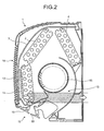
- Fig. 2 is a cross-section of an internal configuration of the indoor equipment.
- an indoor equipment 1 of the air conditioner includes a first intake 18 to take air in a room therein, and an indoor heat exchangers 2, 4, and 12 to cool or heat the air in the room that has been taken therein through the first intake 18.
- the indoor equipment 1 further includes an outlet 10 to return the air that is heat-exchanged by the heat exchangers 2, 4, and 12 in the room, a fan 15 to take air in through the first intake 18 and to blow out the heat-exchanged air to the room from the outlet 10, a gas adsorption filter 11 that is arranged at a position between the indoor heat exchanger 12 and the first intake 18 and near the indoor heat exchanger 12 on an upper stream side in an air flow path, a ventilator 13 that is arranged on one side of the indoor equipment 1, and a prefilter 3 that is arranged inside the indoor equipment 1 from a front part toward an upper part, and that removes impurities such as dust and dirt from the air that is led to the indoor heat exchangers 12, 2, and 4 through the first intake 18, as main components. Because the first intake 18, the indoor heat exchangers 12, 2, and 4, the outlet 10, the fan 15, and the prefilter 3 are well-known techniques, the explanations thereof are omitted herein.
- Fig. 3 is a front view of a configuration of the ventilator.
- an opening 9 is formed long in the horizontal direction above the gas adsorption filter 11, and the ventilator 13 includes a duct 20 having a discharge fan 5 at an end.
- the discharge fan 5 communicates on a downstream side thereof with air outside the room in which the indoor equipment 1 is installed.
- the ventilator 13 functions as a discharge mechanism that discharges atmosphere inside the indoor equipment 1 of the air conditioner to the outside.
- the gas adsorption filter 11 is held in a case (frame) as a holder, and has a function of absorbing and removing harmful substances such as a foul odor component and VOC included in air taken. It is not necessary to particularly limit the arrangement of the ventilator 13 from the point of view of the discharge of atmosphere inside the indoor equipment 1 to the outside. However, it is preferable that the opening 9 be arranged at a position at least higher than the gas adsorption filter 11 so that ascending gas molecules that have been desorbed from the gas adsorption filter 11 are efficiently discharged, from the view point of bearing a part of a filter regenerating function.
- the heat exchangers 12, 2, and 4 are used as heat sources that conduct heat to the gas adsorption filter 11. Therefore, as well as being arranged on the inside of the first intake 18 for the function thereof, the gas adsorption filter 11 is preferably arranged as close to the heat exchangers 12, 2 and 4 as possible.
- louver 19 of the outlet 10 Prior to bringing the heat exchangers 12, 2 and 4 to high temperatures by means of the heat sources, a louver 19 of the outlet 10 is closed, and the fan 15 is run at a low speed.
- the louver 19 is not necessarily be required to be closed, it is preferable that the louver 19 be closed to prevent the gas component desorbed and concentrated in the indoor equipment 1 from leaking, and to perform the discharge of the gas components efficiently by enhancing the hermeticity inside the indoor equipment 1 to make the pressure inside the indoor equipment negative.
- the fan 15 be run to exchange heat to some extent to prevent failure of the air conditioning system because if very little heat exchange is executed when the heat exchangers 12, 2, and 4 are set to high temperatures, a large quantity of a liquid-phase refrigerant flows into an expansion valve, and thus there is a possibility of causing malfunction such as abnormal noise.
- the output of the fan 15 be the minimum output within an allowable range of a refrigerant system load of the air conditioner.
- a refrigerant gas at a high temperature is fed to the heat exchangers 12, 2, and 4, and the heat exchangers 12, 2, and 4 are heated to high temperatures, for example, a temperature about 70C° ⁇ 10C°, within an allowable range for control of a compressor (not shown) and the expansion valve included in the air conditioner.
- gas adsorption filter 11 gas components that have been adsorbed are desorbed, thereby regenerating the gas adsorption filter 11.
- the effect can be obtained even with a temperature that can normally be set to the indoor equipment 1 with a remote control or the like as a filter regeneration temperature.
- the temperature is set to the highest temperature allowable as an air conditioning system, more gas molecules are likely to be desorbed from the gas adsorption filter, and therefore it is preferable.
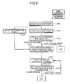
- Fig. 8 is a flowchart of a specific filter regeneration control.
- the air conditioner is started (Step S101), and then stopped (Step S102).
- a total operating time since last filter regeneration control is checked, in most cases, by means of a timer integrated in a computer program that is executed on a computer of a control device. It is then determined whether the total time has exceeded a predetermined time, for example, 125 hours (Step S103). If not exceeded, it is determined that the regeneration control is not necessary, and the control is ended.
- a predetermined time for example, 125 hours
- Step S104 When the total time has exceeded the predetermined time, the fan of the indoor equipment is rotated at a slow speed, and a discharge fan of the ventilator is run (Step S104). Thereafter, a heating-up control is executed to heat the heat exchangers to high temperatures (Step S105). If possible, a temperature inside the indoor equipment and the duration of the filter regeneration control are measured (Step S106). When the duration has exceeded a predetermined time, for example, 1 hour, it is determined that sufficient filter regeneration has been performed, to end the control. When the filter regeneration is to be executed forcibly irrespective of the total operating time since the last filter regeneration control, a mode for forcibly executing the filter regeneration can be set independently from the flow of the control (Step S107).
- the filter regeneration control can be executable by adding the procedure above mentioned to a computer program for a control computer that is usually included in an air conditioner.
- a filter regeneration function for a gas adsorption filter can be given to an air conditioner having a ventilator, without changing the configuration thereof.
- the present invention is characterized such that a second intake 7 (see Figs. 1 , 3, and 4 ) is arranged at a front part of the duct 20 constituting the ventilator 13 in addition to the configuration according to the above embodiment. Moreover, a damper (rotating opening/shutting door) 21 is arranged in the second intake 7. When the damper 21 is open, air is taken also through the second intake 7, which is formed when the damper 21 is open, and a function as a normal ventilator in which pressure drop is low and that can exhaust air in large volume is obtained. When the damper 21 is closed, to efficiently discharge gas molecules that are desorbed from the gas adsorption filter 11 and concentrated inside the indoor equipment 1, air is taken through an opening 22 that is arranged above the gas adsorption filter 11.
- the gas adsorption filter 11 when the gas adsorption filter 11 is arranged between the second intake 7 and the discharge fan 5, a strong flow of air is generated between the second intake 7 and the discharge fan 5, and as a result, the desorbed gas components can be discharged efficiently.
- the second intake 7 is arranged to generate such an air flow.
- a heater is used as a heat source to conduct heat to the gas adsorption filter 11.
- various heaters are placed on a filter holder 31.
- an electrically-heated wire (resistance wire) 34 such as a nichrome wire and a canthal wire is run throughout a surface of a filter holder 33.
- another type of heater such as a PTC (positive temperature coefficient) heater, and an elastomer heater can be attached on the filter holder 33.
- the gas adsorption filter 11 is directly heated up, and gas components can be desorbed efficiently.
- a heater is arranged on the filter holder 31 or 33 as a heat source to regenerate the gas adsorption filter 11
- the filter holder 31 or 33 which are conventionally arranged, with a heater
- a large-scale structure is not required, and the cost therefore can also be low.
- this arrangement does not increase airflow resistance of the gas adsorption filter 11, the need for design modification (upsizing of a fan or a motor) associated with this arrangement can be eliminated.
- the heater can be used together with the heated heat exchangers 12, 2, and 4.
- the gas adsorption filter 11 can take various forms such as a sheet form, a pleats form, a honeycomb form, and a corrugated form.
- materials of the filter using a synthetic fiber such as polypropylene, polyester, and a polyamide-containing synthetic fiber, or a natural fiber such as cellulose and rayon as a base, one that carries thereon an adsorbent such as activated carbon and zeolite, one itself having a high adsorption effect such as an activated carbon fiber and polyacrylic acid, or one formed by directly shaping an inorganic porous material of clay mineral such as cordierite and sepiolite into the above forms can be used. It is preferable that the material have a property that at least odorous components are desorbed when heat of a heat source is applied. It is because removal of odorous components is the foremost requirement for the gas adsorption filter 11.
- the air conditioner and the filter regeneration control method for the air conditioner according to the present invention are useful as an air conditioner including a discharge mechanism that discharges atmosphere inside the indoor equipment of the air conditioner to outside of a room in which the indoor equipment is installed, and useful for control thereof.
Landscapes
- Engineering & Computer Science (AREA)
- Chemical & Material Sciences (AREA)
- Combustion & Propulsion (AREA)
- Mechanical Engineering (AREA)
- General Engineering & Computer Science (AREA)
- Physics & Mathematics (AREA)
- Thermal Sciences (AREA)
- Chemical Kinetics & Catalysis (AREA)
- General Chemical & Material Sciences (AREA)
- Air Filters, Heat-Exchange Apparatuses, And Housings Of Air-Conditioning Units (AREA)
- Air Conditioning Control Device (AREA)
- Disinfection, Sterilisation Or Deodorisation Of Air (AREA)
Claims (7)
- Klimaanlage, umfassend:einen Gasadsorptionsfilter (1 1 ; 32), der schädliche Gasanteile in Luft adsorbiert, die durch einen ersten Einlass (18) in die Innenanlage strömt,einen Filterhalter (31 ; 33), der den Filter (1 1 ; 32) zwischen dem ersten Einlass (18) und einem Wärmetauscher (2, 4, 12) hält, eine Wärmequelle, die Wärme zum Filter (1 1 ; 32) leitet, undeinen Entleerungsmechanismus (13), der ein Rohr (20) umfasst, das an einem Ende einen Entleerungslüfter (5) aufweist, der Luft aus einer Innenanlage (1) der Klimaanlage in die äußere Umgebung eines Raumes, in dem die Innenanlage (1) installiert ist, durch das genannte Rohr (20) hinaustreibt, das innen durch den genannten Entleerungsmechanismus (13) begrenzt ist,dadurch gekennzeichnet, dass der genannte Entleerungsmechanismus (13) umfasst: einen zweiten Einlass (7), der an einem Vorderteil des genannten Rohrs (20) angeordnet ist, und einen Schieber (21), der im genannten zweiten Einlass (7) angeordnet ist, um auf Wunsch eine Luftströmung durch den genannten zweiten Einlass (7) zu ermöglichen.
- Klimaanlage nach Patentanspruch 1, in der die Wärmequelle ein Heizelement (34) ist, das an einer Oberfläche des Filterhalters (31 ; 33) angeordnet ist.
- Klimaanlage nach Patentanspruch 1 , in der die Wärmequelle ein Wärmetauscher (2, 4, 12) ist und eine Steuereinheit aufweist, die den Wärmetauscher (2, 4, 12) auf hohe Temperatur regelt und eine Luftklappe (19) schließt und einen Lüfter (15) dazu veranlasst, mit geringer Geschwindigkeit zu rotieren.
- Klimaanlage nach Patentanspruch 1 , in der der Gasadsorptionsfilter (11; 32) zwischen dem zweiten Einlass (7) und dem Entleerungsmechanismus (13) angeordnet ist.
- Klimaanlage nach irgendeinem der Patentansprüche 1 bis 3, in der eine Öffnung (9) des Entleerungsmechanismus (13) innerhalb der Innenanlage (1) an einer Stelle angeordnet ist, die mindestens höher gelegen ist, als der Filter (1 1 ; 32).
- Klimaanlage nach irgendeinem der Patentansprüche 1 bis 3, in der ein Werkstoff des Filters (1 1 , 32) ein Werkstoff ist, von dem mindestens Geruchskomponenten durch die Wärme der Heizquelle desorbiert werden.
- Filterregenerationssteuerverfahren für eine Klimaanlage mit einem Entleerungsmechanismus (13), der Luft aus einer Innenanlage (1) der Klimaanlage in die äußere Umgebung eines Raumes, in dem die Innenanlage (1) installiert ist, hinaustreibt, wobei in der Klimaanlage ein Gasadsorptionsfilter (11 , 32), der schädliche Gasanteile der Luft adsorbiert, die durch einen ersten Einlass (18) in die Innenanlage (1) strömt, von einem Filterhalter (31; 33) zwischen dem ersten Einlass (18) und einem Wärmetauscher (2, 4, 12) gehalten wird, wobei das Filterregenerationssteuerverfahren umfasst:Steuerung eines Lüfters (15) der Innenanlage (1) derart, dass er mit niedriger Geschwindigkeit rotiert;Steuerung zur Betätigung des Entleerungsmechanismus (13), und Steuerung derart, dass der Wärmetauscher (2, 4, 12) auf eine Temperatur gebracht wird, die gleich oder höher ist, als eine höchste im Normalbetrieb einstellbare Temperatur,dadurch gekennzeichnet, dass der genannte Schritt der Überwachung zur Betätigung des Entleerungsmechanismus (13) die wahlweise Ermöglichung einer Luftströmung durch einen zweiten Einlass (7) des genannten Entleerungsmechanismus (13) umfasst.
Applications Claiming Priority (2)
| Application Number | Priority Date | Filing Date | Title |
|---|---|---|---|
| JP2006267917A JP5101070B2 (ja) | 2006-09-29 | 2006-09-29 | 空気調和装置、および空気調和装置のフィルタ再生制御方法 |
| PCT/JP2007/068538 WO2008041543A1 (en) | 2006-09-29 | 2007-09-25 | Air conditioner and filter regeneration control method for air conditioner |
Publications (3)
| Publication Number | Publication Date |
|---|---|
| EP2068090A1 EP2068090A1 (de) | 2009-06-10 |
| EP2068090A4 EP2068090A4 (de) | 2011-12-21 |
| EP2068090B1 true EP2068090B1 (de) | 2013-09-25 |
Family
ID=39268404
Family Applications (1)
| Application Number | Title | Priority Date | Filing Date |
|---|---|---|---|
| EP07828355.3A Ceased EP2068090B1 (de) | 2006-09-29 | 2007-09-25 | Klimaanlage und filterregenerationssteuerverfahren für eine klimaanlage |
Country Status (3)
| Country | Link |
|---|---|
| EP (1) | EP2068090B1 (de) |
| JP (1) | JP5101070B2 (de) |
| WO (1) | WO2008041543A1 (de) |
Families Citing this family (3)
| Publication number | Priority date | Publication date | Assignee | Title |
|---|---|---|---|---|
| JP6044201B2 (ja) * | 2012-09-06 | 2016-12-14 | 株式会社富士通ゼネラル | 脱臭機 |
| CN103691218A (zh) * | 2013-11-16 | 2014-04-02 | 冯晓宏 | 过滤器清洁单元、自清洁空气净化设备及其使用方法 |
| CN113932317A (zh) * | 2021-10-20 | 2022-01-14 | 海信(山东)空调有限公司 | 空气处理装置以及空调器室内机 |
Family Cites Families (12)
| Publication number | Priority date | Publication date | Assignee | Title |
|---|---|---|---|---|
| JPH02128030A (ja) | 1988-11-05 | 1990-05-16 | Nippon Denso Co Ltd | トイレ用脱臭装置 |
| JPH03233237A (ja) * | 1990-02-08 | 1991-10-17 | Matsushita Electric Ind Co Ltd | 空気調和機およびその脱臭フィルターの再生方法 |
| DE4030144C1 (de) * | 1990-09-24 | 1992-04-23 | Mercedes-Benz Aktiengesellschaft, 7000 Stuttgart, De | |
| JP3141659B2 (ja) * | 1993-12-02 | 2001-03-05 | 松下電器産業株式会社 | 脱臭ユニットおよび脱臭機能付空気調和機 |
| JPH10290829A (ja) | 1997-04-18 | 1998-11-04 | Daikin Ind Ltd | 空気清浄用吸着体の再生機、空気清浄装置及び空気清浄システム |
| JP2001276196A (ja) * | 2000-04-03 | 2001-10-09 | Matsushita Electric Ind Co Ltd | 空気調和機と脱臭用フィルターの利用方法 |
| JP4297625B2 (ja) * | 2001-03-23 | 2009-07-15 | 東芝キヤリア株式会社 | 空気調和機 |
| DE10130731A1 (de) * | 2001-06-20 | 2003-01-09 | Gerd Gaiser | Adsorptions-Innenraumfilter mit zyklischer Regenerierung für Kraftfahrzeuge |
| FI20031207L (fi) * | 2003-05-13 | 2005-02-08 | Hydrocell Ltd Oy | Suodatusmenetelmä ja suodatinlaite |
| ITTO20030810A1 (it) * | 2003-10-15 | 2004-01-13 | Novaengineering S A S Di Mario | Davanzale attrezzato per il condizionamento, la qualita' dell'aria ilrisparmio energetico e la domotica. |
| JP2005265362A (ja) * | 2004-03-22 | 2005-09-29 | Matsushita Electric Ind Co Ltd | 空気調和機 |
| JP2005321114A (ja) * | 2004-05-06 | 2005-11-17 | Matsushita Electric Ind Co Ltd | 空気調和機 |
-
2006
- 2006-09-29 JP JP2006267917A patent/JP5101070B2/ja not_active Expired - Fee Related
-
2007
- 2007-09-25 EP EP07828355.3A patent/EP2068090B1/de not_active Ceased
- 2007-09-25 WO PCT/JP2007/068538 patent/WO2008041543A1/ja not_active Ceased
Also Published As
| Publication number | Publication date |
|---|---|
| WO2008041543A1 (en) | 2008-04-10 |
| JP2008089209A (ja) | 2008-04-17 |
| JP5101070B2 (ja) | 2012-12-19 |
| EP2068090A1 (de) | 2009-06-10 |
| EP2068090A4 (de) | 2011-12-21 |
Similar Documents
| Publication | Publication Date | Title |
|---|---|---|
| EP2358459B1 (de) | Luftreiniger mit entfeuchtungsfunktion | |
| US8366803B2 (en) | Air cleaner having regenerative filter, and method for regenerative of air cleaner filter | |
| KR20170063088A (ko) | 반도체 생산현장의 voc 가스 제거 기능을 갖는 공기 정화장치 | |
| CN108139095A (zh) | 气体过滤系统和方法 | |
| JP2011247566A (ja) | デシカント空調機 | |
| JP2000107545A (ja) | 活性炭フィルタを備えた空調装置 | |
| EP2068090B1 (de) | Klimaanlage und filterregenerationssteuerverfahren für eine klimaanlage | |
| KR101590578B1 (ko) | 물리적 이산화탄소 흡착제를 이용한 승용차용 이산화탄소 흡착 장치 | |
| JP5290782B2 (ja) | 循環型換気システムにおける空気中汚染物質除去装置 | |
| EP0715878B1 (de) | Luftfilter mit Regenerierungsverfahren | |
| JP5039600B2 (ja) | 空気調和機 | |
| JP2010139190A (ja) | 空調機の外気導入装置 | |
| KR101970766B1 (ko) | 차량용 공조 장치 | |
| KR101584112B1 (ko) | 차량용 공기 청정기 | |
| JP5185648B2 (ja) | 空気調和機 | |
| KR100494587B1 (ko) | 차량용 공기정화장치 | |
| JP6092733B2 (ja) | 設備機器 | |
| JP2006266608A (ja) | Voc除去機能付きレンジフード | |
| JP5192840B2 (ja) | 空気調和機 | |
| JP5192839B2 (ja) | 空気調和機の脱臭フィルタ再生方法 | |
| JP5039599B2 (ja) | 空気調和機 | |
| JP3834972B2 (ja) | 空気清浄装置 | |
| KR200387748Y1 (ko) | 공기정화겸용 실외공기유입장치 | |
| JP4897391B2 (ja) | 室内空気清浄化システム | |
| JP2009192130A (ja) | 空気調和機 |
Legal Events
| Date | Code | Title | Description |
|---|---|---|---|
| PUAI | Public reference made under article 153(3) epc to a published international application that has entered the european phase |
Free format text: ORIGINAL CODE: 0009012 |
|
| 17P | Request for examination filed |
Effective date: 20090319 |
|
| AK | Designated contracting states |
Kind code of ref document: A1 Designated state(s): ES GB IT |
|
| AX | Request for extension of the european patent |
Extension state: AL BA HR MK RS |
|
| A4 | Supplementary search report drawn up and despatched |
Effective date: 20111121 |
|
| RIC1 | Information provided on ipc code assigned before grant |
Ipc: F24F 3/16 20060101ALI20111115BHEP Ipc: F24F 11/02 20060101ALI20111115BHEP Ipc: F24F 1/00 20110101AFI20111115BHEP Ipc: F24F 11/04 20060101ALI20111115BHEP |
|
| DAX | Request for extension of the european patent (deleted) | ||
| GRAP | Despatch of communication of intention to grant a patent |
Free format text: ORIGINAL CODE: EPIDOSNIGR1 |
|
| INTG | Intention to grant announced |
Effective date: 20130416 |
|
| GRAS | Grant fee paid |
Free format text: ORIGINAL CODE: EPIDOSNIGR3 |
|
| GRAA | (expected) grant |
Free format text: ORIGINAL CODE: 0009210 |
|
| RIN1 | Information on inventor provided before grant (corrected) |
Inventor name: TANAKA, DAISUKE Inventor name: KOJIMA, SUSUMU |
|
| AK | Designated contracting states |
Kind code of ref document: B1 Designated state(s): ES GB IT |
|
| REG | Reference to a national code |
Ref country code: GB Ref legal event code: FG4D |
|
| PG25 | Lapsed in a contracting state [announced via postgrant information from national office to epo] |
Ref country code: ES Free format text: LAPSE BECAUSE OF FAILURE TO SUBMIT A TRANSLATION OF THE DESCRIPTION OR TO PAY THE FEE WITHIN THE PRESCRIBED TIME-LIMIT Effective date: 20130925 |
|
| PLBE | No opposition filed within time limit |
Free format text: ORIGINAL CODE: 0009261 |
|
| STAA | Information on the status of an ep patent application or granted ep patent |
Free format text: STATUS: NO OPPOSITION FILED WITHIN TIME LIMIT |
|
| GBPC | Gb: european patent ceased through non-payment of renewal fee |
Effective date: 20131225 |
|
| 26N | No opposition filed |
Effective date: 20140626 |
|
| PG25 | Lapsed in a contracting state [announced via postgrant information from national office to epo] |
Ref country code: GB Free format text: LAPSE BECAUSE OF NON-PAYMENT OF DUE FEES Effective date: 20131225 |
|
| PGFP | Annual fee paid to national office [announced via postgrant information from national office to epo] |
Ref country code: IT Payment date: 20230810 Year of fee payment: 17 |
|
| PG25 | Lapsed in a contracting state [announced via postgrant information from national office to epo] |
Ref country code: IT Free format text: LAPSE BECAUSE OF NON-PAYMENT OF DUE FEES Effective date: 20240925 |