EP2068110B1 - Système de verrouillage pour une arme à plusieurs canons - Google Patents
Système de verrouillage pour une arme à plusieurs canons Download PDFInfo
- Publication number
- EP2068110B1 EP2068110B1 EP20080168897 EP08168897A EP2068110B1 EP 2068110 B1 EP2068110 B1 EP 2068110B1 EP 20080168897 EP20080168897 EP 20080168897 EP 08168897 A EP08168897 A EP 08168897A EP 2068110 B1 EP2068110 B1 EP 2068110B1
- Authority
- EP
- European Patent Office
- Prior art keywords
- trigger
- lock system
- base part
- intermediate levers
- levers
- Prior art date
- Legal status (The legal status is an assumption and is not a legal conclusion. Google has not performed a legal analysis and makes no representation as to the accuracy of the status listed.)
- Not-in-force
Links
Images


Classifications
-
- F—MECHANICAL ENGINEERING; LIGHTING; HEATING; WEAPONS; BLASTING
- F41—WEAPONS
- F41A—FUNCTIONAL FEATURES OR DETAILS COMMON TO BOTH SMALLARMS AND ORDNANCE, e.g. CANNONS; MOUNTINGS FOR SMALLARMS OR ORDNANCE
- F41A19/00—Firing or trigger mechanisms; Cocking mechanisms
- F41A19/06—Mechanical firing mechanisms, e.g. counterrecoil firing, recoil actuated firing mechanisms
- F41A19/18—Mechanical firing mechanisms, e.g. counterrecoil firing, recoil actuated firing mechanisms for multibarrel guns or multiple guns
- F41A19/19—Mechanical firing mechanisms, e.g. counterrecoil firing, recoil actuated firing mechanisms for multibarrel guns or multiple guns with single-trigger firing possibility
- F41A19/21—Mechanical firing mechanisms, e.g. counterrecoil firing, recoil actuated firing mechanisms for multibarrel guns or multiple guns with single-trigger firing possibility having only one trigger
-
- F—MECHANICAL ENGINEERING; LIGHTING; HEATING; WEAPONS; BLASTING
- F41—WEAPONS
- F41A—FUNCTIONAL FEATURES OR DETAILS COMMON TO BOTH SMALLARMS AND ORDNANCE, e.g. CANNONS; MOUNTINGS FOR SMALLARMS OR ORDNANCE
- F41A17/00—Safety arrangements, e.g. safeties
- F41A17/56—Sear safeties, i.e. means for rendering ineffective an intermediate lever transmitting trigger movement to firing pin, hammer, bolt or sear
- F41A17/58—Sear safeties, i.e. means for rendering ineffective an intermediate lever transmitting trigger movement to firing pin, hammer, bolt or sear automatically operated, i.e. operated by breech opening or closing movement
Definitions
- the invention relates to a lock system for a multi-barreled weapon, in particular a firearm, according to the preamble of claim 1.
- Such a lock system is from the DE 10 2004 041 054 B3 (Starting point for the preamble of independent claim 1) known.
- This also includes two slidably mounted on a Baskülenteil arranged percussion pieces, which are each associated with a rotatable between a holding position and release position locking lever and each cooperating with this trigger bar.
- the trigger mechanism for connecting the trigger and trigger rods consists here of a rocker, which is pivotally hinged to a movable in the Baskülenteil switch piece. The rocker is also displaceable with respect to the changeover piece and is pushed forward by a spring.
- a pendulum mass is arranged, which is connected to the rocker so that the rocker is displaced relative to the Umschalt Faculty both during acceleration and during the deceleration of the weapon, thereby preventing engagement with the trigger rods. Since the trigger rods thus can not be attacked by the rocker during the acceleration and deceleration phase of the weapon, a high level of security against unconscious and unwanted second shot triggering ("doubling") is achieved in the delivery of the first shot.
- the pendulum mass is relatively far above and requires a correspondingly large receiving space.
- the system reacts with a certain delay due to the articulation and design of the pendulum mass, which can lead to problems at lower deduction weights. With small deduction weights, a small deflection of the trigger caused by the recoil can already be sufficient to trigger another shot.
- the DE 197 49 290 C2 and the DE 101 18 046 A1 also show lock systems that should avoid double.
- the object of the invention is to provide a lock system of the type mentioned, which allows a compact design and even at low deduction weights a high Security against unwanted triggering, especially a second shot when firing the intended first shot guaranteed.
- associated intermediate levers are arranged on the displaceable between a front release position and a rear securing position of the main body.
- the trigger also includes a slidable separator which is slidable relative to the trigger between a rear actuating position for connecting the trigger to the intermediate levers and a front separating position for interrupting the connection between the trigger and the intermediate levers.
- the two intermediate levers can actuate the associated trigger rods to trigger a shot, while in the rear securing position of the body, the intermediate levers are spaced from the trigger rods to prevent firing.
- the securing position is taken by the body when the weapon is braked at a conditional by the recoil backward movement of the shoulder of the shooter or rebounds from this back to the front. Then the main body is pressed by the inertial force against the Baskülenteil further back into the securing position, so that there is no connection between the trigger and the trigger bars in this phase and thus no further shot can be delivered.
- the separator arranged on the trigger stops at a backward movement due to the recoil following the delivery of a shot due to its inertial mass and is displaced relative to the trigger in the forward separating position. In the front separating position, the trigger is separated from the intermediate levers, so that no second shot can be triggered in this phase.
- the lock system according to the invention is particularly suitable for low deduction weights and offers a high level of security against the unwanted firing of a second Shooting both during the backward movement caused by the recoil and during the recoil of the weapon from the shoulder of the shooter.
- Another significant advantage of the lock system according to the invention is that it can be easily converted from a Einabzugsystem to a system with two deductions. All you have to do is replace the trigger with a double trigger. Otherwise, no significant changes are required.
- the separator is slidably guided on an upwardly projecting guide pin of the trigger and is pressed by a compression spring in the rear operating position.
- the compression spring is suitably clamped between the separator and a front web at the top of the trigger.
- Additional security can be achieved in a further advantageous embodiment in that in the main body of the intermediate levers associated locking slide are arranged, which are displaceable in the base body slidably between a rear release position and a front locking position.
- the sliding in the main body gate valves are designed so that they initially stop at a conditional by a recoil backward movement of the Baskülenteils due to their inertia and reach within the body in the front locking position. In this blocking position, the intermediate levers are blocked by the pushers, which further security against unintentional triggering of another shot is achieved during the conditional by the recoil backward movement of the weapon.
- the gate valves can react relatively quickly even at lower accelerations and thus prevent unwanted actuation of the intermediate lever in a backward movement of the weapon.
- the arranged within the body locking slide also require only a small space, so that an extremely compact design of the lock system is made possible.
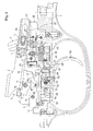
- FIGS. 1 to 5 lock system shown in different positions includes two on a lower Baskülenteil (lock plate) 1 slidably guided, juxtaposed strikes 2 and 3 for the operation of two not shown here firing pin of a multi-barreled weapon, especially a firearm.
- the Schlag Federatione 2 and 3 are each accommodated a striker spring 4 and a corresponding clamping bolt 5.
- the two clamping bolts 5 by a cocking slide, not shown here via a clamping lever 6 from an in FIG. 1 shown rear relaxation position in a FIG. 2 displaced shown front clamping position.
- the two striking pieces 2 and 3 are each a rotatable between a holding position and a release position latching lever 7 and 8 and one cooperating with this trigger bar 9 and 10 assigned.
- the two juxtaposed latching levers 7 and 8 are pivotally connected about a first transverse pin 11 to the Baskülenteil 1 and have upper locking lugs 12 and 13 for holding the hammer 2 and 3 in the rear holding position.
- the locking lever 7 and 8 are acted upon so that the locking lugs 12 and 13 are pushed upwards.
- the two trigger rods 9 and 10 are arranged in the manner of a two-armed lever about a second transverse pin 14 pivotally mounted on the Baskülenteil 1 and have at the bottom of her by a respective compression spring 15 downwardly acted upon the rear lever arm a groove 16 for receiving one at the lower end of the associated Locking lever 7 and 8 arranged pin 17.
- the compression springs 15 are clamped between the Baskülenteil 1 and the front lever arms of the trigger rods 9 and 10.
- the grooves 16 and the pins 17 are matched to one another such that the pins 17 when lifting the rear lever arms of the trigger rods 9 and 10 out of engagement with the grooves 16 of the trigger rods 9 and 10, so that the locking lever 7 and 8 are released and the beaters 2 and 3 can move under the action of the beaters 4 forward.
- FIG. 6 The actuation of the trigger rods 9 and 10 to release the locking lever 7 and 8 via two in FIG. 6 shown in a plan view intermediate lever 18 and 19, which are mounted parallel to each other on a base body 20 about a common transverse axis 21 pivotally.
- the main body 20 is slidably guided on the lower Baskülenteil 1 in the longitudinal direction.
- the two intermediate levers 18 and 19 are separated from each other by a separating web 22 in the front region of the base body 20.
- two locking slides 23 and 24 arranged next to one another are also displaceably guided in the longitudinal direction of the bascule part 1 and thus in the longitudinal direction of the firearm.
- a passage 25 is provided for the tensioning lever 6 in the base body 20.
- Both in the intermediate levers 18 and 19 as well as in the locking slides 23 and 24 are adjustable in height adjusting elements 26 and 27 arranged in the form of grub screws.
- intermediate levers 18 and 19 are designed as a two-armed pivot lever, which at the front end of their seen in the weft direction in front of a bore 28 for the transverse axis 21 front lever arm a forwardly projecting lug 29 and 30 for engagement with the associated trigger rods 9 and 10 included , At the bottom of their front lever arm, the intermediate lever 18 and 19 downwardly projecting projections 31 and 32, respectively.
- the front adjusting element 26 are arranged between the lugs 29 and 30 and the bores 28 for the transverse axis 21 and lie with its lower end on a shoulder 33 of the base body 20. By turning the front adjusting elements 26, the height of the lugs 29 and 30 relative to the base body 20 can be adjusted.
- the intermediate levers 18 and 19 further include at their lying behind the bore 28 rear lever arm a rearwardly projecting lug 34 and 35, which can be undercut by the disposed in the locking slide 23 and 24 rear actuator 27.
- a respective vertical compression spring 36 is clamped between the rear lever arm of the intermediate lever 18 and 19 and the base body 20 .
- the vertical compression spring 36 of the front lever arm of the intermediate lever 18 and 19 and thus the nose 29 and 30 is pressed with the projections 31 and 32 down.
- these compression springs 37 and 38 the locking slide 23 and 24 are pressed backwards in the direction of a rear wall 39 of the base body 20. From the FIGS. 6 and 7 also shows that the intermediate lever 19 is slightly longer than the intermediate lever 18 and the nose 30 are offset with the projection 32 of the intermediate lever 19 relative to the nose 29 and the projection 31 of the intermediate lever 18 to the front.
- the two gate valves 23 and 24 have a slimmer in plan view and the side view raised front portion 40 and a widened in plan view, in side view, however, narrower rear portion 41.
- the front portion 40 of the locking slide 23 and 24 is an in FIG. 7 recognizable slot 42 provided.
- On the inner sides of the two rear portions 41 are located inside projecting lugs 43 for conditioning the clamping lever 6.
- At the front of the widened rear portions 41 are in FIG. 7 recognizable blind holes 44 provided for the compression springs 37 and 38, respectively.
- the main body 20 includes an in.
- Baskülenteils 1 designed as a deduction deduction 52 is rotatably mounted about a rotation axis 53.
- a compression spring 54 which is clamped between the Baskülenteil 1 and a bore 55 in the trigger 52 behind the axis of rotation 53 height-adjustable threaded pin 56, the trigger 52 is pushed forward.
- trigger 52 includes on its upper side an upwardly projecting front web 57 and an upwardly projecting central guide pin 58 in which a transverse bore 59 is arranged for the axis of rotation 53. Behind the transverse bore 59 in the guide pin 58 which is provided at its lower end with a threaded vertical bore 55 for the compression spring 54 and the threaded pin 56 is provided.
- the separator 60 includes a continuous from top to bottom slot 61, which has a greater length than the guide pin 58 but only slightly greater width for sliding guide on the guide pin 58.
- the separator 60 also includes a perpendicular to the slot 61, extending transversely through the separator 60 further slot 62 through which the axis of rotation 53 extends.
- a blind hole 63 At the front end of the separator 60 is a blind hole 63 for one end of a in the FIGS. 1 to 5
- the compression spring 64 is supported on the front web 57 of the trigger 52 from. By the compression spring 64, the separator 60 is thus seen in the weft direction pushed backwards.
- FIG. 1 In the unstressed initial position take the above-described parts of the lock system according to the invention in FIG. 1 shown position.
- the two hammer pieces 2 and 3 bear with a front edge on the latching lugs 12 and 13 of the two locking levers 7 and 8 located in the upper holding position.
- the tensioning lever 6 is located in the rearwardly pivoted position, so that the clamping bolts 5 are in the rear position and the two impact springs 4 are only slightly tensioned.
- the two locking slide 23 and 24 back to the rear wall 39 of the body 20 and this pressed against the force of the compression spring 50 to the rear in the retracted securing position.
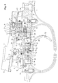
- FIG. 2 the lock system is shown in the cocked position just before the first shot is fired.
- the tensioning lever 6 is pushed forward and the two impact springs 4 stretched.
- the tensioning lever 6 is in the forward position, the base body 20 via the locking slide 23 and 24 is no longer held in the retracted securing position, but pressed by the compression spring 50 forward in the direction of the transverse pin 49 until the in FIG. 2 rear intermediate lever 19 with its further protruding nose 30, the associated trigger bar 10 engages under and with its downwardly projecting projection 32 for resting on the associated threaded pin 66 in the in FIG. 11 the upper bore 65 of the separator 60 passes.
- the nose 29 of the intermediate lever 18, however, is spaced from the associated trigger bar 9 and also the projection 31 of the trigger bar 9 is not on the associated threaded pin 66 of the separator 60 on. Due to the force of the compression springs 37, the locking slides 23 and 24 continue to be pressed against the rear wall 39 of the main body 20. In this rear release position of the locking slide 23 and 24, the rear lugs 34 and 35 of the intermediate levers 18 and 19 are not under attack by the set screws as adjusting elements 27, so that the two intermediate levers 18 and 19 are freely rotatable. If the trigger 52 is actuated in this cocked position, the intermediate lever 19 raises the rear end of the trigger rod 10, whereby the locking lever 8 is released for rotation. This allows the hammer 3 to move forward to deliver a first shot, as shown in FIG FIG. 4 is shown.
- the weapon and thus also the Baskülenteil 1 are first accelerated backwards in the direction of the shooter's shoulder.
- the two gate valves 23 and 24 initially remain due to their inertial mass, so that the rear lugs 34 and 35 of the intermediate lever 18 and 19 according to FIG. 4 get over the control elements 27. In this position, a rotation of the intermediate lever 18 and 19 and thus triggering a further shot is prevented by the voltage applied to the underside of the projections 34 and 35 control elements 27.
- Baskülenteils 1 When caused by the recoil backward movement of Baskülenteils 1 also remains displaceable on the trigger 52 separator 60 due to its inertial mass stand and is pressed against the force of the compression spring 64 against the web 57 in the front release position.
- the threaded pins 66 against the Projections 31 and 32 displaced forward so that the not yet actuated intermediate lever 18 associated threaded pin 66 is spaced from the projection 31 of the intermediate lever 18. This achieves an additional backup.
- the base body 20 continues to move backward due to its inertial mass relative to the bascule part 1 against the force of the compression spring 50 and decreases in the FIG. 5 shown rear position.
- the lugs 29 and 30 of the two intermediate levers 18 and 19 are again spaced from the trigger bars 9 and 10, so that in this phase, even when pivoting the intermediate lever 18 and 19 no further shot can be triggered.
- the lower projections 31 and 32 of the intermediate levers 18 and 19 are spaced from the associated grub screws 66 in the separator, so that there is no connection between the trigger and the intermediate levers 18 and 19.
Landscapes
- Engineering & Computer Science (AREA)
- General Engineering & Computer Science (AREA)
- Toys (AREA)
- Buckles (AREA)
- Portable Nailing Machines And Staplers (AREA)
- Containers And Packaging Bodies Having A Special Means To Remove Contents (AREA)
Claims (15)
- Système de verrouillage pour une arme à plusieurs canons, en particulier pour une arme à canons superposés, comportant au moins deux supports-percuteurs (2, 3) disposés de manière à pouvoir coulisser au niveau d'une pièce à bascule (1), comportant respectivement un levier d'arrêt (7, 8) associé à chaque support-percuteur (2, 3) servant à maintenir ou à libérer des supports-percuteurs (2, 3) et un dispositif de détente, qui est doté de tiges de détente (9, 10) associées aux leviers à crans (7, 8), d'une détente (52) et d'un corps de base (20) pouvant être coulissé par rapport à la partie de bascule (1) du fait de sa masse d'inertie, caractérisé en ce que des leviers intermédiaires (18, 19) associés aux tiges de détente (9, 10) sont disposés au niveau du corps de base (20) pouvant être coulissé entre une positon de déclenchement avant et une position de sécurité arrière, et en ce que la détente (52) est dotée d'une pièce de séparation (60) pouvant en outre être coulissée, laquelle peut être coulissée par rapport à la détente (52) entre une position d'actionnement arrière servant à relier la détente (52) aux leviers intermédiaires (18, 19) et une position de séparation avant servant à séparer la détente (52) des leviers intermédiaires (18, 19) par sa masse d'inertie.
- Système de verrouillage selon la revendication 1, caractérisé en ce que la pièce de séparation (60) est guidée de manière à pouvoir être coulissée sur un tourillon de guidage (58) de la détente (52), faisant saillie vers le haut.
- Système de verrouillage selon la revendication 1 ou 2, caractérisé en ce que la pièce de séparation (60) est pressée par un ressort de compression (64) dans une position d'actionnement arrière.
- Système de verrouillage selon la revendication 3, caractérisé en ce que le ressort de compression (64) est tendu entre la pièce de séparation (60) et une entretoise (57) avant, au niveau du côté supérieur de la détente (52).
- Système de verrouillage selon l'une quelconque des revendications 1 à 4, caractérisé en ce que des éléments d'actionnement (66) pouvant être déplacés destinés à venir en prise avec des parties faisant saillies (31, 32) vers le bas des leviers intermédiaires (18, 19) sont disposés dans la pièce de séparation (60).
- Système de verrouillage selon la revendication 5, caractérisé en ce que les parties faisant saillie (31, 32) des leviers intermédiaires (18, 19) sont décalées les unes par rapport aux autres.
- Système de verrouillage selon l'une quelconque des revendications 1 à 6, caractérisé en ce que les leviers intermédiaires (18, 19) présentent des ergots (29, 30) avant décalés les uns par rapport aux autres destinés à venir en prise avec les tiges de détente (9, 10).
- Système de verrouillage selon l'une quelconque des revendications 2 à 7, caractérisé en ce qu'un alésage transversal (59) pour un axe de rotation (53) de la détente (52) est pratiqué dans le tourillon de guidage (58).
- Système de verrouillage selon la revendication 8, caractérisé en ce qu'un trou oblong (61) pour l'axe de rotation (53) de la détente (52) est prévu dans la pièce de séparation (60).
- Système de verrouillage selon l'une quelconque des revendications 1 à 9, caractérisé en ce que des poussoirs de blocage (23, 24) associés aux leviers intermédiaires (18, 19) sont disposés dans le corps de base (20), lesquels poussoirs de blocage sont guidés de manière à pouvoir être coulissés dans le corps de base (20) et peuvent être coulissés par rapport au corps de base (20) entre une position de libération arrière et une position de blocage avant.
- Système de verrouillage selon la revendication 10, caractérisé en ce que les poussoirs de blocage (23, 24) présentent un élément de réglage (27), qui vient en prise par le bas, dans la position de blocage avant, avec un appendice (34, 35) arrière des leviers de déclenchement (18, 19) afin d'empêcher toute rotation des leviers intermédiaires (18, 19).
- Système de verrouillage selon la revendication 10 ou 11, caractérisé en ce que les poussoirs de blocage (23, 24) sont soumis à l'action de ressorts de compression (37, 38) dans la position de libération arrière.
- Système de verrouillage selon l'une quelconque des revendications 10 à 12, caractérisé en ce que les poussoirs de blocage (23, 24) sont guidés dans le corps de base (20) de manière à pouvoir être coulissés, à travers des trous oblongs (42) et une tige transversale (21).
- Système de verrouillage selon l'une quelconque des revendications 1 à 13, caractérisé en ce que le corps de base (20) est pressé par un ressort de compression (50) dans la position de déclenchement avant.
- Système de verrouillage selon la revendication 14, caractérisé en ce que le corps de base (20) peut être coulissé dans la position de sécurité arrière par un levier de serrage (6) par l'intermédiaire des poussoirs de blocage (23, 24).
Applications Claiming Priority (1)
| Application Number | Priority Date | Filing Date | Title |
|---|---|---|---|
| DE200710059097 DE102007059097B3 (de) | 2007-12-07 | 2007-12-07 | Schlosssystem für eine mehrläufige Waffe |
Publications (3)
| Publication Number | Publication Date |
|---|---|
| EP2068110A2 EP2068110A2 (fr) | 2009-06-10 |
| EP2068110A3 EP2068110A3 (fr) | 2011-03-16 |
| EP2068110B1 true EP2068110B1 (fr) | 2013-01-09 |
Family
ID=40157685
Family Applications (1)
| Application Number | Title | Priority Date | Filing Date |
|---|---|---|---|
| EP20080168897 Not-in-force EP2068110B1 (fr) | 2007-12-07 | 2008-11-12 | Système de verrouillage pour une arme à plusieurs canons |
Country Status (4)
| Country | Link |
|---|---|
| EP (1) | EP2068110B1 (fr) |
| DE (1) | DE102007059097B3 (fr) |
| DK (1) | DK2068110T3 (fr) |
| RU (1) | RU2401966C2 (fr) |
Families Citing this family (6)
| Publication number | Priority date | Publication date | Assignee | Title |
|---|---|---|---|---|
| DE102008021690A1 (de) * | 2008-04-30 | 2009-11-05 | Blaser Finanzholding Gmbh | Spannvorrichtung für ein Schloss eines Gewehrs |
| RU2550104C1 (ru) * | 2014-01-17 | 2015-05-10 | Общество С Ограниченной Ответственностью "Промтехнология" | Предохранительный механизм |
| DE202014100947U1 (de) | 2014-03-03 | 2015-06-09 | L&O Hunting Group GmbH | Handfeuerwaffe mit einem Schlosssystem |
| DE102014102774B3 (de) * | 2014-03-03 | 2014-12-18 | L&O Hunting Group GmbH | Handfeuerwaffe mit einem Schlosssystem |
| DE102015121121A1 (de) | 2015-12-04 | 2017-06-08 | L&O Hunting Group GmbH | Waffenschloss und Handfeuerwaffe mit einem derartigen Waffenschloss |
| DE202015106612U1 (de) | 2015-12-04 | 2017-03-07 | L&O Hunting Group GmbH | Waffenschloss und Handfeuerwaffe mit einem derartigen Waffenschloss |
Family Cites Families (4)
| Publication number | Priority date | Publication date | Assignee | Title |
|---|---|---|---|---|
| GB819800A (en) * | 1954-11-23 | 1959-09-09 | John Eyton Orr | Improvements relating to shot-guns |
| DE19749290C2 (de) * | 1997-11-07 | 2003-02-13 | Blaser Horst Jagdwaffen | Abzugsvorrichtung für doppelläufige Gewehre, bei der das Doppeln vermieden wird |
| DE10118046A1 (de) * | 2001-04-11 | 2002-10-24 | Blaser Horst Jagdwaffen | Schloßsystem für mehrläufige Gewehre |
| DE102004041054B3 (de) * | 2004-08-25 | 2006-03-16 | S.A.T. Swiss Arms Technology Ag | Schlosssystem für eine mehrläufige Waffe |
-
2007
- 2007-12-07 DE DE200710059097 patent/DE102007059097B3/de not_active Expired - Fee Related
-
2008
- 2008-11-12 DK DK08168897T patent/DK2068110T3/da active
- 2008-11-12 EP EP20080168897 patent/EP2068110B1/fr not_active Not-in-force
- 2008-12-04 RU RU2008147794/02A patent/RU2401966C2/ru not_active IP Right Cessation
Also Published As
| Publication number | Publication date |
|---|---|
| DE102007059097B3 (de) | 2009-01-29 |
| RU2008147794A (ru) | 2010-06-10 |
| EP2068110A2 (fr) | 2009-06-10 |
| RU2401966C2 (ru) | 2010-10-20 |
| EP2068110A3 (fr) | 2011-03-16 |
| DK2068110T3 (da) | 2013-04-15 |
Similar Documents
| Publication | Publication Date | Title |
|---|---|---|
| EP2449331B1 (fr) | Protection contre les impacts pour arme à feu | |
| EP0730135A1 (fr) | Mécanisme de détente pour armes à feu sans chien | |
| EP2068110B1 (fr) | Système de verrouillage pour une arme à plusieurs canons | |
| EP1379828B1 (fr) | Systeme de verrouillage pour armes a plusieurs tubes-canons | |
| DE102004041054B3 (de) | Schlosssystem für eine mehrläufige Waffe | |
| EP4224106B1 (fr) | Arme à répétition | |
| EP2916094B1 (fr) | Arme de poing dotée d'un système de verrouillage | |
| EP0437736B1 (fr) | Module de culasse démontable pour fusil | |
| WO2004072571A1 (fr) | Systeme de detente pour armes a feu de poing | |
| EP4224105B1 (fr) | Dispositif de détente d'une arme à feu portative | |
| DE1428774C3 (de) | Abzugsvorrichtung für automatische Feuerwaffen zum Auslösen von Einzel- und Dauerfeuer | |
| EP2078917B1 (fr) | Système de culasse pour une arme à plusieurs canons | |
| EP3176536B1 (fr) | Culasse pour arme et arme de poing dotée d'une telle culasse | |
| EP1387140B1 (fr) | Verrou pour des fusils à plusiers coups | |
| EP2109747B1 (fr) | Bloc de culasse pour une arme à canon basculant | |
| EP2045563B1 (fr) | Mécanisme de mise à feu pour une arme à plusieurs canons | |
| DE3640606C1 (en) | Breech action (bolt) for rifles | |
| EP1597530B1 (fr) | Systeme de detente pour armes a feu de poing | |
| DE202007017125U1 (de) | Schlosssystem für eine mehrläufige Waffe | |
| DE202007013961U1 (de) | Schlosssystem für eine mehrläufige Waffe | |
| EP1821059B1 (fr) | Dispositif de détente pour arme à feu | |
| DE202008000370U1 (de) | Einschloss-System für eine mehrläufige Waffe | |
| DE202004013261U1 (de) | Schlosssystem für eine mehrläufige Waffe | |
| AT502720B1 (de) | Verschlussblock für eine kipplaufwaffe | |
| DE202022100685U1 (de) | Abzugseinrichtung einer Handfeuerwaffe |
Legal Events
| Date | Code | Title | Description |
|---|---|---|---|
| PUAI | Public reference made under article 153(3) epc to a published international application that has entered the european phase |
Free format text: ORIGINAL CODE: 0009012 |
|
| AK | Designated contracting states |
Kind code of ref document: A2 Designated state(s): AT BE BG CH CY CZ DE DK EE ES FI FR GB GR HR HU IE IS IT LI LT LU LV MC MT NL NO PL PT RO SE SI SK TR |
|
| AX | Request for extension of the european patent |
Extension state: AL BA MK RS |
|
| PUAL | Search report despatched |
Free format text: ORIGINAL CODE: 0009013 |
|
| AK | Designated contracting states |
Kind code of ref document: A3 Designated state(s): AT BE BG CH CY CZ DE DK EE ES FI FR GB GR HR HU IE IS IT LI LT LU LV MC MT NL NO PL PT RO SE SI SK TR |
|
| AX | Request for extension of the european patent |
Extension state: AL BA MK RS |
|
| RIC1 | Information provided on ipc code assigned before grant |
Ipc: F41A 17/58 20060101ALI20110208BHEP Ipc: F41A 19/21 20060101AFI20090226BHEP |
|
| 17P | Request for examination filed |
Effective date: 20110430 |
|
| AKX | Designation fees paid |
Designated state(s): AT BE BG CH CY CZ DE DK EE ES FI FR GB GR HR HU IE IS IT LI LT LU LV MC MT NL NO PL PT RO SE SI SK TR |
|
| GRAP | Despatch of communication of intention to grant a patent |
Free format text: ORIGINAL CODE: EPIDOSNIGR1 |
|
| RIC1 | Information provided on ipc code assigned before grant |
Ipc: F41A 19/21 20060101AFI20120525BHEP Ipc: F41A 17/58 20060101ALI20120525BHEP |
|
| GRAS | Grant fee paid |
Free format text: ORIGINAL CODE: EPIDOSNIGR3 |
|
| GRAA | (expected) grant |
Free format text: ORIGINAL CODE: 0009210 |
|
| AK | Designated contracting states |
Kind code of ref document: B1 Designated state(s): AT BE BG CH CY CZ DE DK EE ES FI FR GB GR HR HU IE IS IT LI LT LU LV MC MT NL NO PL PT RO SE SI SK TR |
|
| REG | Reference to a national code |
Ref country code: GB Ref legal event code: FG4D Free format text: NOT ENGLISH |
|
| REG | Reference to a national code |
Ref country code: CH Ref legal event code: EP Ref country code: AT Ref legal event code: REF Ref document number: 592988 Country of ref document: AT Kind code of ref document: T Effective date: 20130115 |
|
| REG | Reference to a national code |
Ref country code: CH Ref legal event code: NV Representative=s name: LUCHS AND PARTNER PATENTANWAELTE, CH |
|
| REG | Reference to a national code |
Ref country code: IE Ref legal event code: FG4D Free format text: LANGUAGE OF EP DOCUMENT: GERMAN |
|
| REG | Reference to a national code |
Ref country code: CH Ref legal event code: NV Representative=s name: LUCHS AND PARTNER PATENTANWAELTE, CH |
|
| REG | Reference to a national code |
Ref country code: DE Ref legal event code: R096 Ref document number: 502008009059 Country of ref document: DE Effective date: 20130307 |
|
| REG | Reference to a national code |
Ref country code: DK Ref legal event code: T3 |
|
| REG | Reference to a national code |
Ref country code: SK Ref legal event code: T3 Ref document number: E 13549 Country of ref document: SK |
|
| PG25 | Lapsed in a contracting state [announced via postgrant information from national office to epo] |
Ref country code: SI Free format text: LAPSE BECAUSE OF FAILURE TO SUBMIT A TRANSLATION OF THE DESCRIPTION OR TO PAY THE FEE WITHIN THE PRESCRIBED TIME-LIMIT Effective date: 20130109 |
|
| REG | Reference to a national code |
Ref country code: NL Ref legal event code: VDEP Effective date: 20130109 |
|
| REG | Reference to a national code |
Ref country code: LT Ref legal event code: MG4D |
|
| PG25 | Lapsed in a contracting state [announced via postgrant information from national office to epo] |
Ref country code: NO Free format text: LAPSE BECAUSE OF FAILURE TO SUBMIT A TRANSLATION OF THE DESCRIPTION OR TO PAY THE FEE WITHIN THE PRESCRIBED TIME-LIMIT Effective date: 20130409 Ref country code: IS Free format text: LAPSE BECAUSE OF FAILURE TO SUBMIT A TRANSLATION OF THE DESCRIPTION OR TO PAY THE FEE WITHIN THE PRESCRIBED TIME-LIMIT Effective date: 20130509 Ref country code: BG Free format text: LAPSE BECAUSE OF FAILURE TO SUBMIT A TRANSLATION OF THE DESCRIPTION OR TO PAY THE FEE WITHIN THE PRESCRIBED TIME-LIMIT Effective date: 20130409 Ref country code: LT Free format text: LAPSE BECAUSE OF FAILURE TO SUBMIT A TRANSLATION OF THE DESCRIPTION OR TO PAY THE FEE WITHIN THE PRESCRIBED TIME-LIMIT Effective date: 20130109 Ref country code: SE Free format text: LAPSE BECAUSE OF FAILURE TO SUBMIT A TRANSLATION OF THE DESCRIPTION OR TO PAY THE FEE WITHIN THE PRESCRIBED TIME-LIMIT Effective date: 20130109 Ref country code: ES Free format text: LAPSE BECAUSE OF FAILURE TO SUBMIT A TRANSLATION OF THE DESCRIPTION OR TO PAY THE FEE WITHIN THE PRESCRIBED TIME-LIMIT Effective date: 20130420 |
|
| PG25 | Lapsed in a contracting state [announced via postgrant information from national office to epo] |
Ref country code: PL Free format text: LAPSE BECAUSE OF FAILURE TO SUBMIT A TRANSLATION OF THE DESCRIPTION OR TO PAY THE FEE WITHIN THE PRESCRIBED TIME-LIMIT Effective date: 20130109 Ref country code: PT Free format text: LAPSE BECAUSE OF FAILURE TO SUBMIT A TRANSLATION OF THE DESCRIPTION OR TO PAY THE FEE WITHIN THE PRESCRIBED TIME-LIMIT Effective date: 20130509 Ref country code: NL Free format text: LAPSE BECAUSE OF FAILURE TO SUBMIT A TRANSLATION OF THE DESCRIPTION OR TO PAY THE FEE WITHIN THE PRESCRIBED TIME-LIMIT Effective date: 20130109 Ref country code: LV Free format text: LAPSE BECAUSE OF FAILURE TO SUBMIT A TRANSLATION OF THE DESCRIPTION OR TO PAY THE FEE WITHIN THE PRESCRIBED TIME-LIMIT Effective date: 20130109 Ref country code: GR Free format text: LAPSE BECAUSE OF FAILURE TO SUBMIT A TRANSLATION OF THE DESCRIPTION OR TO PAY THE FEE WITHIN THE PRESCRIBED TIME-LIMIT Effective date: 20130410 |
|
| PG25 | Lapsed in a contracting state [announced via postgrant information from national office to epo] |
Ref country code: HR Free format text: LAPSE BECAUSE OF FAILURE TO SUBMIT A TRANSLATION OF THE DESCRIPTION OR TO PAY THE FEE WITHIN THE PRESCRIBED TIME-LIMIT Effective date: 20130109 |
|
| PG25 | Lapsed in a contracting state [announced via postgrant information from national office to epo] |
Ref country code: RO Free format text: LAPSE BECAUSE OF FAILURE TO SUBMIT A TRANSLATION OF THE DESCRIPTION OR TO PAY THE FEE WITHIN THE PRESCRIBED TIME-LIMIT Effective date: 20130109 Ref country code: EE Free format text: LAPSE BECAUSE OF FAILURE TO SUBMIT A TRANSLATION OF THE DESCRIPTION OR TO PAY THE FEE WITHIN THE PRESCRIBED TIME-LIMIT Effective date: 20130109 |
|
| PLBE | No opposition filed within time limit |
Free format text: ORIGINAL CODE: 0009261 |
|
| STAA | Information on the status of an ep patent application or granted ep patent |
Free format text: STATUS: NO OPPOSITION FILED WITHIN TIME LIMIT |
|
| PG25 | Lapsed in a contracting state [announced via postgrant information from national office to epo] |
Ref country code: CY Free format text: LAPSE BECAUSE OF FAILURE TO SUBMIT A TRANSLATION OF THE DESCRIPTION OR TO PAY THE FEE WITHIN THE PRESCRIBED TIME-LIMIT Effective date: 20130109 |
|
| 26N | No opposition filed |
Effective date: 20131010 |
|
| REG | Reference to a national code |
Ref country code: DE Ref legal event code: R097 Ref document number: 502008009059 Country of ref document: DE Effective date: 20131010 |
|
| GBPC | Gb: european patent ceased through non-payment of renewal fee |
Effective date: 20131112 |
|
| PG25 | Lapsed in a contracting state [announced via postgrant information from national office to epo] |
Ref country code: MC Free format text: LAPSE BECAUSE OF FAILURE TO SUBMIT A TRANSLATION OF THE DESCRIPTION OR TO PAY THE FEE WITHIN THE PRESCRIBED TIME-LIMIT Effective date: 20130109 |
|
| REG | Reference to a national code |
Ref country code: IE Ref legal event code: MM4A |
|
| PG25 | Lapsed in a contracting state [announced via postgrant information from national office to epo] |
Ref country code: IE Free format text: LAPSE BECAUSE OF NON-PAYMENT OF DUE FEES Effective date: 20131112 |
|
| PG25 | Lapsed in a contracting state [announced via postgrant information from national office to epo] |
Ref country code: GB Free format text: LAPSE BECAUSE OF NON-PAYMENT OF DUE FEES Effective date: 20131112 |
|
| PG25 | Lapsed in a contracting state [announced via postgrant information from national office to epo] |
Ref country code: TR Free format text: LAPSE BECAUSE OF FAILURE TO SUBMIT A TRANSLATION OF THE DESCRIPTION OR TO PAY THE FEE WITHIN THE PRESCRIBED TIME-LIMIT Effective date: 20130109 |
|
| PG25 | Lapsed in a contracting state [announced via postgrant information from national office to epo] |
Ref country code: HU Free format text: LAPSE BECAUSE OF FAILURE TO SUBMIT A TRANSLATION OF THE DESCRIPTION OR TO PAY THE FEE WITHIN THE PRESCRIBED TIME-LIMIT; INVALID AB INITIO Effective date: 20081112 Ref country code: LU Free format text: LAPSE BECAUSE OF NON-PAYMENT OF DUE FEES Effective date: 20131112 |
|
| PG25 | Lapsed in a contracting state [announced via postgrant information from national office to epo] |
Ref country code: MT Free format text: LAPSE BECAUSE OF FAILURE TO SUBMIT A TRANSLATION OF THE DESCRIPTION OR TO PAY THE FEE WITHIN THE PRESCRIBED TIME-LIMIT Effective date: 20130109 |
|
| REG | Reference to a national code |
Ref country code: FR Ref legal event code: PLFP Year of fee payment: 8 |
|
| REG | Reference to a national code |
Ref country code: FR Ref legal event code: PLFP Year of fee payment: 9 |
|
| REG | Reference to a national code |
Ref country code: FR Ref legal event code: PLFP Year of fee payment: 10 |
|
| PGFP | Annual fee paid to national office [announced via postgrant information from national office to epo] |
Ref country code: CZ Payment date: 20181031 Year of fee payment: 11 Ref country code: FI Payment date: 20181120 Year of fee payment: 11 Ref country code: SK Payment date: 20181031 Year of fee payment: 11 Ref country code: DK Payment date: 20181126 Year of fee payment: 11 Ref country code: AT Payment date: 20181120 Year of fee payment: 11 |
|
| PGFP | Annual fee paid to national office [announced via postgrant information from national office to epo] |
Ref country code: FR Payment date: 20181127 Year of fee payment: 11 Ref country code: IT Payment date: 20181122 Year of fee payment: 11 Ref country code: CH Payment date: 20181126 Year of fee payment: 11 Ref country code: BE Payment date: 20181122 Year of fee payment: 11 |
|
| PGFP | Annual fee paid to national office [announced via postgrant information from national office to epo] |
Ref country code: DE Payment date: 20190110 Year of fee payment: 11 |
|
| REG | Reference to a national code |
Ref country code: DE Ref legal event code: R119 Ref document number: 502008009059 Country of ref document: DE |
|
| REG | Reference to a national code |
Ref country code: FI Ref legal event code: MAE |
|
| REG | Reference to a national code |
Ref country code: DK Ref legal event code: EBP Effective date: 20191130 |
|
| REG | Reference to a national code |
Ref country code: CH Ref legal event code: PL |
|
| PG25 | Lapsed in a contracting state [announced via postgrant information from national office to epo] |
Ref country code: LI Free format text: LAPSE BECAUSE OF NON-PAYMENT OF DUE FEES Effective date: 20191130 Ref country code: CH Free format text: LAPSE BECAUSE OF NON-PAYMENT OF DUE FEES Effective date: 20191130 Ref country code: FI Free format text: LAPSE BECAUSE OF NON-PAYMENT OF DUE FEES Effective date: 20191112 Ref country code: CZ Free format text: LAPSE BECAUSE OF NON-PAYMENT OF DUE FEES Effective date: 20191112 |
|
| REG | Reference to a national code |
Ref country code: SK Ref legal event code: MM4A Ref document number: E 13549 Country of ref document: SK Effective date: 20191112 |
|
| REG | Reference to a national code |
Ref country code: AT Ref legal event code: MM01 Ref document number: 592988 Country of ref document: AT Kind code of ref document: T Effective date: 20191112 |
|
| REG | Reference to a national code |
Ref country code: BE Ref legal event code: MM Effective date: 20191130 |
|
| PG25 | Lapsed in a contracting state [announced via postgrant information from national office to epo] |
Ref country code: SK Free format text: LAPSE BECAUSE OF NON-PAYMENT OF DUE FEES Effective date: 20191112 |
|
| PG25 | Lapsed in a contracting state [announced via postgrant information from national office to epo] |
Ref country code: DK Free format text: LAPSE BECAUSE OF NON-PAYMENT OF DUE FEES Effective date: 20191130 Ref country code: IT Free format text: LAPSE BECAUSE OF NON-PAYMENT OF DUE FEES Effective date: 20191112 Ref country code: DE Free format text: LAPSE BECAUSE OF NON-PAYMENT OF DUE FEES Effective date: 20200603 Ref country code: FR Free format text: LAPSE BECAUSE OF NON-PAYMENT OF DUE FEES Effective date: 20191130 |
|
| PG25 | Lapsed in a contracting state [announced via postgrant information from national office to epo] |
Ref country code: BE Free format text: LAPSE BECAUSE OF NON-PAYMENT OF DUE FEES Effective date: 20191130 Ref country code: AT Free format text: LAPSE BECAUSE OF NON-PAYMENT OF DUE FEES Effective date: 20191112 |