EP2068357A1 - Corps de couvercle et récipient recevant des substrats - Google Patents
Corps de couvercle et récipient recevant des substrats Download PDFInfo
- Publication number
- EP2068357A1 EP2068357A1 EP07828756A EP07828756A EP2068357A1 EP 2068357 A1 EP2068357 A1 EP 2068357A1 EP 07828756 A EP07828756 A EP 07828756A EP 07828756 A EP07828756 A EP 07828756A EP 2068357 A1 EP2068357 A1 EP 2068357A1
- Authority
- EP
- European Patent Office
- Prior art keywords
- door structure
- casing
- container body
- locking mechanism
- rotator
- Prior art date
- Legal status (The legal status is an assumption and is not a legal conclusion. Google has not performed a legal analysis and makes no representation as to the accuracy of the status listed.)
- Granted
Links
Images


Classifications
-
- B—PERFORMING OPERATIONS; TRANSPORTING
- B65—CONVEYING; PACKING; STORING; HANDLING THIN OR FILAMENTARY MATERIAL
- B65D—CONTAINERS FOR STORAGE OR TRANSPORT OF ARTICLES OR MATERIALS, e.g. BAGS, BARRELS, BOTTLES, BOXES, CANS, CARTONS, CRATES, DRUMS, JARS, TANKS, HOPPERS, FORWARDING CONTAINERS; ACCESSORIES, CLOSURES, OR FITTINGS THEREFOR; PACKAGING ELEMENTS; PACKAGES
- B65D55/00—Accessories for container closures not otherwise provided for
- B65D55/02—Locking devices; Means for discouraging or indicating unauthorised opening or removal of closure
- B65D55/14—Applications of locks, e.g. of permutation or key-controlled locks
-
- H—ELECTRICITY
- H10—SEMICONDUCTOR DEVICES; ELECTRIC SOLID-STATE DEVICES NOT OTHERWISE PROVIDED FOR
- H10P—GENERIC PROCESSES OR APPARATUS FOR THE MANUFACTURE OR TREATMENT OF DEVICES COVERED BY CLASS H10
- H10P72/00—Handling or holding of wafers, substrates or devices during manufacture or treatment thereof
- H10P72/10—Handling or holding of wafers, substrates or devices during manufacture or treatment thereof using carriers specially adapted therefor, e.g. front opening unified pods [FOUP]
-
- B—PERFORMING OPERATIONS; TRANSPORTING
- B65—CONVEYING; PACKING; STORING; HANDLING THIN OR FILAMENTARY MATERIAL
- B65D—CONTAINERS FOR STORAGE OR TRANSPORT OF ARTICLES OR MATERIALS, e.g. BAGS, BARRELS, BOTTLES, BOXES, CANS, CARTONS, CRATES, DRUMS, JARS, TANKS, HOPPERS, FORWARDING CONTAINERS; ACCESSORIES, CLOSURES, OR FITTINGS THEREFOR; PACKAGING ELEMENTS; PACKAGES
- B65D85/00—Containers, packaging elements or packages, specially adapted for particular articles or materials
-
- B—PERFORMING OPERATIONS; TRANSPORTING
- B65—CONVEYING; PACKING; STORING; HANDLING THIN OR FILAMENTARY MATERIAL
- B65D—CONTAINERS FOR STORAGE OR TRANSPORT OF ARTICLES OR MATERIALS, e.g. BAGS, BARRELS, BOTTLES, BOXES, CANS, CARTONS, CRATES, DRUMS, JARS, TANKS, HOPPERS, FORWARDING CONTAINERS; ACCESSORIES, CLOSURES, OR FITTINGS THEREFOR; PACKAGING ELEMENTS; PACKAGES
- B65D85/00—Containers, packaging elements or packages, specially adapted for particular articles or materials
- B65D85/30—Containers, packaging elements or packages, specially adapted for particular articles or materials for articles particularly sensitive to damage by shock or pressure
- B65D85/38—Containers, packaging elements or packages, specially adapted for particular articles or materials for articles particularly sensitive to damage by shock or pressure for delicate optical, measuring, calculating or control apparatus
-
- H—ELECTRICITY
- H10—SEMICONDUCTOR DEVICES; ELECTRIC SOLID-STATE DEVICES NOT OTHERWISE PROVIDED FOR
- H10P—GENERIC PROCESSES OR APPARATUS FOR THE MANUFACTURE OR TREATMENT OF DEVICES COVERED BY CLASS H10
- H10P72/00—Handling or holding of wafers, substrates or devices during manufacture or treatment thereof
- H10P72/10—Handling or holding of wafers, substrates or devices during manufacture or treatment thereof using carriers specially adapted therefor, e.g. front opening unified pods [FOUP]
- H10P72/19—Handling or holding of wafers, substrates or devices during manufacture or treatment thereof using carriers specially adapted therefor, e.g. front opening unified pods [FOUP] closed carriers
- H10P72/1914—Handling or holding of wafers, substrates or devices during manufacture or treatment thereof using carriers specially adapted therefor, e.g. front opening unified pods [FOUP] closed carriers characterised by locking systems
-
- B—PERFORMING OPERATIONS; TRANSPORTING
- B65—CONVEYING; PACKING; STORING; HANDLING THIN OR FILAMENTARY MATERIAL
- B65D—CONTAINERS FOR STORAGE OR TRANSPORT OF ARTICLES OR MATERIALS, e.g. BAGS, BARRELS, BOTTLES, BOXES, CANS, CARTONS, CRATES, DRUMS, JARS, TANKS, HOPPERS, FORWARDING CONTAINERS; ACCESSORIES, CLOSURES, OR FITTINGS THEREFOR; PACKAGING ELEMENTS; PACKAGES
- B65D2585/00—Containers, packaging elements or packages specially adapted for particular articles or materials
- B65D2585/68—Containers, packaging elements or packages specially adapted for particular articles or materials for machines, engines, or vehicles in assembled or dismantled form
- B65D2585/86—Containers, packaging elements or packages specially adapted for particular articles or materials for machines, engines, or vehicles in assembled or dismantled form for electrical components
Definitions
- the present invention relates to a door structure for a container body for storing substrates such as semiconductor wafers and the like as well as a substrate storage container.
- a conventional substrate storage container is comprised of a container body for storing a plurality of substrates such as semiconductor wafers in alignment and a door structure to be detachably fitted into the open front portion of the container body.
- This substrate storage container is set to semiconductor wafer processing equipment in a mass-production process of semiconductor parts, and its door structure is automatically opened and closed by a door opening/closing device of the processing equipment, to meet the demands for cleanness (see Patent documents 1 and 2).
- the substrate storage container is basically constructed such that the door structure is opened and closed automatically by the door opening/closing device of the processing equipment, the door structure is manually opened and closed by an operator when a trouble takes place or when a test is carried out.
- the operator detaches the door structure from the container body using a dedicated small tool or detaches the door structure from the container body by turning the opening/closing handle for manual operation, which is previously attached in a pivotable manner on the front side of the door structure.
- the conventional substrate storage container is thus constructed and the door structure is manually detached from the container body using a dedicated small tool or using an opening/closing handle for manual operation.
- a special tool is used, the tool need be provided for each processing stage, and there is a risk of it being lost because it is small.
- an opening/closing handle is used, it is necessary to previously attach the opening/closing handle in a pivotable manner on the front side of the door structure, hence it takes time and labor to do this work and there is also the problem that the configuration is complicated.
- the opening/closing handle Since the opening/closing handle is movable, there is also the problem that particles are prone to arise around the frictionally movable parts due to vibration and impacts during transportation. Moreover, there is more than a small concern that it takes a long time for a drying process of the door structure after washing because washing water is prone to stay around the pivot shaft of the opening/closing handle and hollow parts for operation during washing the door structure.
- the present invention has been devised in view of the above, it is therefore an object of the present invention to provide a door structure and a substrate storage container with which there is less fear that even when the door is manually opened and closed, its parts, accessories and the like are lost, with which particles are unlikely to arise due to vibration, impacts and the like during transportation and with which it does not take long time to dry after washing.
- a door structure that is detachably fitted into an opening portion of a container body for storing substrates, includes: a casing to be fitted to the opening portion of the container body; a locking mechanism provided in the casing for locking the casing by causing an engaging piece to project out from the peripheral wall of the casing in a retractable manner based on rotation of a rotator so as to interfere with the inner periphery of the opening portion of the container body; a cover for enclosing the locking mechanism; and an operational window formed in the cover so as to oppose the rotator.
- the locking mechanism may preferably include: an externally operable rotator that is rotatably supported on the casing of the door structure; a plurality of couplers that are supported by the casing and reciprocate inwards and outwards of the casing as the rotator rotates; and a plurality of engaging pieces that are coupled with individual couplers and project from, and retract into, through-holes in the peripheral wall of the casing by reciprocating movement of the couplers.
- the rotator of the locking mechanism includes a manual operating means in the part opposing the operational window.
- the manual operating means may comprise a finger insertion hole formed in the rotator of the locking mechanism. Also, a finger engaging piece may be formed around the finger insertion hole of the rotator. Also, the manual operating means may comprise an operational bar that is formed with the rotator of the locking mechanism and exposed from the operational window. Also, the manual operating means may comprise knurling formed on the rotator of the locking mechanism.
- a substrate storage container is characterized in that one of the door structures according to Claims 1 through 6 is detachably fitted into the opening portion of a container body for storing substrates.
- the inner periphery of the opening portion of the container body may be formed with a plurality of engaging holes to be interfered by the engaging pieces of the locking mechanism.
- the substrates defined in the scope of the claims may at least include a single or plurality of semiconductor wafers, reclaimed wafers, glass wafers and the like of 200 mm, 300 mm and 450 mm in diameter.
- the container body and substrate storage container are not particularly limited to being transparent, opaque, translucent, of a top open box type, of a front open box type, of a bottom open box type, for in-house, for shipment or the like.
- the number, either single or plural, or removability is not particularly limited.
- the engaging piece of this locking mechanism may include a claw, roller and the like.
- the number, either single or plural, or the shape, of the operational window is not particularly limited.
- the operational window may have an arced, circular, rectangular, polygonal, elliptic or other shape.
- the finger insertion hole (either with a bottom or without bottom) of the manual operating means the finger engaging piece and the operational bar (including a lever etc.), their numbers, either single or plural, and the shape are not particularly limited.
- the locking mechanism when the door structure of the container body for storing substrates is opened and closed manually, it is possible to manually operate the locking mechanism to open and close the door structure by inserting fingers, a rod or the like, into the operational window of the cover and turning the rotator of the locking mechanism.
- the present invention has the effect that there is less fear that even when, for example the door structure is manually opened and closed, its parts, accessories and the like are lost and that particles are prevented from arising in the door structure due to even undergoing vibration, impacts and the like during transportation. Further it is possible to speed up the drying operation of the door structure after washing. Further, since it is possible to hook the fingers etc., properly on the rotator of the locking mechanism when the finger insertion hole is used as a manual operating means, the manual operation is made easy.
- the finger insertion hole as the manual operating means is formed with a finger engaging piece, it is possible to positively transfer the operating force from the fingers etc., to the rotator of the locking mechanism.
- the manual operating means is constructed of knurling formed on the rotator of the locking mechanism, it is possible with a simple configuration to prevent fingers etc., from slipping when the rotator of the locking mechanism is operated.
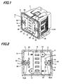
- a substrate storage container of the present embodiment includes a container body 1 for accommodating a plurality of substrates, a door structure 10 to be detachably fitted in a sealing manner into an open front portion 2 of this container body 1.
- This door structure 10 is constructed of a casing 11 detachably fitted into open front portion 2 of container body 1, a plurality of locking mechanisms 14 disposed on the front side of this casing 11 for locking casing 11 by projecting a plurality of engaging claws 21 from the peripheral wall of casing 11 in a retractable manner as each rotary plate 15 is turned so that the claws engage the inner periphery of open front portion 2 of container body 1, a plurality of cover plates 22 attached on the front side of casing 11 to cover individual locking mechanisms 14, and a plurality of operational windows 30 which are each formed in cover plate 22 so as to partially oppose individual rotary plate 15.
- a manual operating means 40 is provided for rotary plate 15 of each locking mechanism 14 at the position opposing operational window 30.
- the substrates are thin round semiconductor wafers (Si wafers and the like) of 300 mm in diameter, and in order to distinguish the crystal orientation and position the semiconductor wafers, part of its periphery is selectively and linearly cut out to form an orientation flat, or part of its periphery is cut out with a substantially narrow groove to form a notch.
- Stored and aligned in container body 1 are 1 to 25 or 1 to 26 substrates.
- container body 1 is injectionmolded using a predetermined molding material into a front open box type having an opening on its front side.
- molding material for this container body 1 include thermoplastic resin such as polycarbonate, cycloolefin polymer, polyether imide, polyether sulfone, polyether ether ketone and the like. This thermoplastic resin is blended with conducive components such as conductive carbon, conductive fibers, metal fibers, conductive high polymers, etc., various antistatic agents, UV absorbers and the like, as appropriate.
- a pair of left and right rear retainers for fitting and holding the rear peripheral part of the substrate are projectively formed on the rear interior side. Pairs of the rear retainers are formed vertically at intervals of a predetermined gap. Further, a pair of left and right teeth that horizontally support substrates at their periphery on both sides are projectively formed on both interior sides of container body 1. Pairs of left and right teeth opposing each other are formed vertically at intervals of a predetermined gap.
- a flat bottom plate of an approximately Y-shape, polygon, triangle or the like is attached and arranged with a plurality of positioning tools having an approximately V-shaped section for positioning to unillustrated processing equipment.
- Attached to the top center of container body 1 is a detachable flange having an approximately rectangular shape, when viewed from top, which is held by an unillustrated transport robot.
- Open front portion 2 of container body 1 is bent and formed to have a step extended outwards, as shown in FIGS. 1 and 2 .
- the flat stepped surface of this step functions to be the seal-forming surface for door structure 10.
- a pair of left and right engaging holes for receiving engaging claws 21 of locking mechanism 14 are hollowed and formed a predetermined distance apart from each other at top and bottom on the inner periphery of open front portion 2 of container body 1 while manual handles to be gripped by the operator are detachably attached in the center of the outer surface of both the left and right side portions of container body 1.
- casing 11 of door structure 10, multiple locking mechanisms 14, multiple cover plates 22 and manual operating means 40 are molded using the same molding material as for container body 1.
- casing 11 is basically formed in a laterally-long rectangular shape having an approximately dish-like section with a central part 12 of an approximately rectangle protruded to the surface side (front side) so as to relatively form hollows on the left and right side portions.
- Locking mechanisms 14 are arranged inside both the left and right hollows while rectangular through-holes are formed at both sides on the top and bottom peripheral walls.
- central part 12 of casing 11 circular suction areas 13 to be suctioned by door opening/closing device of the processing equipment are formed at the top and the bottom on both sides on the front side while an elastic front retainer for fitting and horizontally holding the front edges of substrates is detachably attached on the hollowed interior side.
- a frame-like endless fitting and holding groove having an approximately U-shaped section is formed along the periphery of the interior side of casing 11. Inserted into this fitting and holding groove is an elastically deformable sealing gasket that comes into press-contact with the seal-forming surface of container body 1.
- This sealing gasket is formed endlessly using, for example silicone rubber, fluororubber or the like.
- each locking mechanism 14 includes: a rotary plate 15 that is rotatably supported on the front side of casing 11 and rotationally operated from the outside of door structure 10 by the door opening/closing device of the processing equipment; a pair of coupling plates 19 which each are slidably supported on the front side of casing 11 by a plurality of guide pins and guides and slide vertically inwards and outwards of casing 11 as rotary plate 15 rotates; and a pair of engaging claws 21 which are each axially supported near the through-hole on the peripheral wall of casing 11 and axially coupled by the front end of each coupling plate 19 so as to be projected from and retracted into respective through-holes on the peripheral wall of casing 11 as coupling plates 19 slide.
- Each rotary plate 15 is formed so as to have an approximately convex section while an operational hole 16 having a rectangular shape when viewed from the front, for permitting external operation is hollowed in the circular center portion projected to the front side.
- This rotary plate 15 has a pair of arc slots 17 bored approximately 180° apart from each other along the periphery thereof and also has a pair of flexible bent pieces 18 formed approximately 180° apart on the peripheral edge.
- Each coupling plate 19 as a coupler is provided in the form of a rectangular flat plate, and a cylindrical coupling pin 20 at the end on the front side is fitted in arc slot 17 of rotary plate 15 and coupled therewith.
- the thus constructed coupling plates 19 slide vertically outwards of casing 11 so as to cause engaging claws 21 that will fit to the engaging holes of container body 1 to project out from the through-holes in the peripheral wall.
- the plates slide vertically inwards of casing 11 so as to cause engaging claws 21 to return to their original positions.
- each cover plate 22 is given in a vertical long shape corresponding to either side part of casing 11, and a plurality of flexible engaging pieces 23 that detachably engage casing 11 and the side faces of its central portion are projectively formed.
- This cover plate 22 has an operational opening 24 having a rectangular shape, viewed from the front, which opposes operational hole 16 of rotary plate 15 and communicates therewith. When the operating key of the door opening/closing device is inserted into operational hole 16 of rotary plate 15 through this operational opening 24 and rotated, each locking mechanism 14 is operated from the outside.
- each operational window 30 is formed so that a pair of hollows are arranged in approximately the central portion of each cover plate 22 on the left and right sides of operational opening 24.
- Each operational window 30 has an approximately arc shaped configuration when viewed from the front, partially opposing the front side of rotary plate 15 and functions to allow for manual operation from the outside.
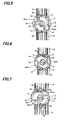
- Manual operating means 40 is formed of, as shown in FIGS. 5 to 7 , a pair of finger insertion holes 41, bored in an approximately sectoral form when viewed from the front, and arranged 180° part from each other in rotary plate 15 at the positions opposing operational windows 30, and finger engagement ribs 42 projectively formed from part of the periphery of each finger insertion hole 41.
- This manual operating means 40 is molded using the same molding material as for container body 1.
- operational window 30 and finger insertion hole 41 are preferably sized conforming to SEMI standard S8 (ergonomics engineering for semiconductor manufacturing equipment) for example.
- finger insertion holes 41 and finger engagement ribs 42 are arranged in rotaryplate 15 at the positions opposing operational windows 30, fingers can be easily inserted so that manual operation will not be hindered. Further, since fingers can be engaged properly when finger insertion holes 41 of manual operating means 40 are used, the manual operation can be made easy. Moreover, use of finger engagement ribs 42 makes it possible to positively transfer the finger's operating force to rotary plate 15.
- FIGS. 9 and 10 show the second embodiment of the present invention.
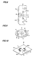
- manual operating means 40 is formed of a pair of operational bars 43 that are projectively formed from the front side of each rotary plate 15 and exposed from operational windows 30 of each cover plate 22.
- Each operational bar 43 is given in the form of a linear short rectangular or square piece and arranged adjacent to the end of each arc slot 17 so as to allow the operator to handle and rotate rotary plate 15 with their fingers.
- Other components are the same as in the above embodiment, so description is omitted.
- FIGS. 11 and 12 show the third embodiment of the present invention.
- manual operating means 40 is formed of a pair of operational bars 43A that are formed 180° apart from each other about the center on the front side of each rotaryplate 15 and is exposed from circular operational windows 30 of each cover plate 22.
- Each operational bar 43A is given as an approximately open V-shaped bent form greater and longer than operational bar 43, and extended radially outwards from the center on the front side of each rotary plate 15 so as to allow the operator to handle and rotate rotaryplate 15 with their fingers.
- Other components are the same as in the above embodiment, so description is omitted.
- each operational bar 43A is greater and longer than operational bar 43, it is obvious that a further improved operability can be obtained.
- FIG. 13 shows the fourth embodiment of the present invention.
- manual operating means 40 is formed by knurling 44 for anti-slipping, which is formed by arranging a plurality of incised ridges side by side or obliquely on the peripheral side of each rotary plate 15 and is exposed from a plurality of rectangular operational windows 30 in each cover plate 22.
- Other components are the same as in the above embodiment, so description is omitted.
Landscapes
- Engineering & Computer Science (AREA)
- Mechanical Engineering (AREA)
- Container, Conveyance, Adherence, Positioning, Of Wafer (AREA)
- Packaging Frangible Articles (AREA)
- Closures For Containers (AREA)
- Packaging Of Annular Or Rod-Shaped Articles, Wearing Apparel, Cassettes, Or The Like (AREA)
Applications Claiming Priority (2)
| Application Number | Priority Date | Filing Date | Title |
|---|---|---|---|
| JP2006275248A JP4841383B2 (ja) | 2006-10-06 | 2006-10-06 | 蓋体及び基板収納容器 |
| PCT/JP2007/069015 WO2008044495A1 (fr) | 2006-10-06 | 2007-09-28 | Corps de couvercle et récipient recevant des substrats |
Publications (3)
| Publication Number | Publication Date |
|---|---|
| EP2068357A1 true EP2068357A1 (fr) | 2009-06-10 |
| EP2068357A4 EP2068357A4 (fr) | 2011-12-28 |
| EP2068357B1 EP2068357B1 (fr) | 2018-07-18 |
Family
ID=39282705
Family Applications (1)
| Application Number | Title | Priority Date | Filing Date |
|---|---|---|---|
| EP07828756.2A Not-in-force EP2068357B1 (fr) | 2006-10-06 | 2007-09-28 | Corps de couvercle et récipient recevant des substrats |
Country Status (7)
| Country | Link |
|---|---|
| US (1) | US8091710B2 (fr) |
| EP (1) | EP2068357B1 (fr) |
| JP (1) | JP4841383B2 (fr) |
| KR (1) | KR101413936B1 (fr) |
| CN (1) | CN101523589B (fr) |
| TW (1) | TW200834786A (fr) |
| WO (1) | WO2008044495A1 (fr) |
Families Citing this family (21)
| Publication number | Priority date | Publication date | Assignee | Title |
|---|---|---|---|---|
| JP5286142B2 (ja) * | 2009-04-10 | 2013-09-11 | 株式会社ディスコ | 加工装置 |
| US8521131B1 (en) | 2010-03-23 | 2013-08-27 | Amazon Technologies, Inc. | Mobile device security |
| CN103354214B (zh) * | 2010-05-07 | 2016-04-06 | 家登精密工业股份有限公司 | 一种具有椭圆门闩结构的前开式圆片盒 |
| CN102263046A (zh) * | 2010-05-26 | 2011-11-30 | 家登精密工业股份有限公司 | 一种具有椭圆门闩结构的前开式圆片盒 |
| TWM410441U (en) * | 2011-02-23 | 2011-08-21 | Hon Hai Prec Ind Co Ltd | Fixing structure of removable electronic device |
| US9965768B1 (en) | 2011-05-19 | 2018-05-08 | Amazon Technologies, Inc. | Location-based mobile advertising |
| KR200465979Y1 (ko) * | 2011-06-08 | 2013-03-20 | 삼성중공업 주식회사 | 도어 |
| JP5715898B2 (ja) | 2011-07-06 | 2015-05-13 | ミライアル株式会社 | 基板収納容器 |
| CN103035559B (zh) * | 2011-09-29 | 2015-04-22 | 中芯国际集成电路制造(北京)有限公司 | 弹性固定轮及包含其的晶圆适配器 |
| TWM425502U (en) * | 2011-10-31 | 2012-03-21 | Hon Hai Prec Ind Co Ltd | Removable electronic device |
| CN104285289B (zh) * | 2012-06-14 | 2016-10-26 | 村田机械株式会社 | 盖开闭装置 |
| WO2014192109A1 (fr) * | 2013-05-29 | 2014-12-04 | ミライアル株式会社 | Récipient de stockage de substrats |
| US8857619B1 (en) * | 2013-09-30 | 2014-10-14 | Taiwan Semiconductor Manufacturing Co., Ltd | Mechanisms for wafer pod and pod door |
| US9184077B2 (en) | 2013-09-30 | 2015-11-10 | Taiwan Semiconductor Manufacturing Co., Ltd | Wafer pod and wafer positioning mechanism thereof |
| JP6591297B2 (ja) * | 2016-01-20 | 2019-10-16 | 信越ポリマー株式会社 | 基板収納容器 |
| US11398395B2 (en) | 2016-12-16 | 2022-07-26 | Entegris, Inc. | Substrate container with latching mechanism having two cam profiles |
| TWI746045B (zh) * | 2020-07-07 | 2021-11-11 | 家登精密工業股份有限公司 | 基板載具鎖扣結構 |
| CN115416974B (zh) * | 2022-09-26 | 2024-08-13 | 重庆工业职业技术学院 | 一种固定资产管理标签及方法 |
| TWI863584B (zh) * | 2023-02-24 | 2024-11-21 | 家登精密工業股份有限公司 | 具有栓鎖穩定機構的門及基板載具 |
| WO2024252868A1 (fr) * | 2023-06-05 | 2024-12-12 | 信越ポリマー株式会社 | Porte pour réceptacle de substrat |
| US20240412994A1 (en) * | 2023-06-06 | 2024-12-12 | Entegris, Inc. | Substrate container, and door locking mechanism thereof |
Family Cites Families (20)
| Publication number | Priority date | Publication date | Assignee | Title |
|---|---|---|---|---|
| US1362647A (en) * | 1916-05-13 | 1920-12-21 | American Hardware Corp | Door and lock therefor |
| US2565669A (en) * | 1950-03-07 | 1951-08-28 | Emma R Dawson | Room occupancy indicator |
| US4490999A (en) * | 1982-09-27 | 1985-01-01 | Castle Nial K | Door lock with indicator |
| US5711427A (en) * | 1996-07-12 | 1998-01-27 | Fluoroware, Inc. | Wafer carrier with door |
| US5915562A (en) * | 1996-07-12 | 1999-06-29 | Fluoroware, Inc. | Transport module with latching door |
| US6010008A (en) * | 1997-07-11 | 2000-01-04 | Fluoroware, Inc. | Transport module |
| JP3556480B2 (ja) * | 1998-08-17 | 2004-08-18 | 信越ポリマー株式会社 | 精密基板収納容器 |
| TW433258U (en) * | 2000-06-23 | 2001-05-01 | Ind Tech Res Inst | Improved door body structure for a pod |
| AU2002227395A1 (en) * | 2000-12-13 | 2002-06-24 | Entergris Cayman Ltd. | System for preventing improper insertion of foup door into foup |
| US6457598B1 (en) * | 2001-03-20 | 2002-10-01 | Prosys Technology Integration, Inc. | Module cover assembly with door latch transmission mechanism for wafer transport module |
| EP1458634A1 (fr) * | 2001-11-27 | 2004-09-22 | Entegris, Inc. | Support de plaquettes a ouverture frontale comportant une mise a la terre realisee par la porte |
| JP4073206B2 (ja) | 2001-12-05 | 2008-04-09 | 信越ポリマー株式会社 | 収納容器の蓋体 |
| US6712213B2 (en) * | 2002-01-15 | 2004-03-30 | Entegris, Inc. | Wafer carrier door and latching mechanism withhourglass shaped key slot |
| US6880718B2 (en) * | 2002-01-15 | 2005-04-19 | Entegris, Inc. | Wafer carrier door and spring biased latching mechanism |
| US6749067B2 (en) * | 2002-01-16 | 2004-06-15 | Entegris, Inc. | Wafer carrier door with form fitting mechanism cover |
| TW534165U (en) * | 2002-09-04 | 2003-05-21 | Ind Tech Res Inst | Latch locking mechanism used in doors of wafer boxes |
| WO2004102655A1 (fr) * | 2003-05-15 | 2004-11-25 | Tdk Corporation | Dispositif propre a dispositif de fermeture/ouverture de boite propre |
| TWI276580B (en) * | 2003-12-18 | 2007-03-21 | Miraial Co Ltd | Lid unit for thin-plate supporting container |
| JP4573566B2 (ja) * | 2004-04-20 | 2010-11-04 | 信越ポリマー株式会社 | 収納容器 |
| US7913437B2 (en) * | 2007-12-06 | 2011-03-29 | Caroline Simmen Domenig | Room occupancy indicator |
-
2006
- 2006-10-06 JP JP2006275248A patent/JP4841383B2/ja active Active
-
2007
- 2007-09-28 CN CN2007800375250A patent/CN101523589B/zh active Active
- 2007-09-28 US US12/444,545 patent/US8091710B2/en active Active
- 2007-09-28 KR KR1020097005092A patent/KR101413936B1/ko active Active
- 2007-09-28 WO PCT/JP2007/069015 patent/WO2008044495A1/fr not_active Ceased
- 2007-09-28 EP EP07828756.2A patent/EP2068357B1/fr not_active Not-in-force
- 2007-10-04 TW TW096137285A patent/TW200834786A/zh unknown
Also Published As
| Publication number | Publication date |
|---|---|
| KR101413936B1 (ko) | 2014-06-30 |
| JP2008098236A (ja) | 2008-04-24 |
| WO2008044495A1 (fr) | 2008-04-17 |
| TW200834786A (en) | 2008-08-16 |
| JP4841383B2 (ja) | 2011-12-21 |
| TWI371816B (fr) | 2012-09-01 |
| EP2068357A4 (fr) | 2011-12-28 |
| CN101523589A (zh) | 2009-09-02 |
| EP2068357B1 (fr) | 2018-07-18 |
| US8091710B2 (en) | 2012-01-10 |
| KR20090075663A (ko) | 2009-07-08 |
| CN101523589B (zh) | 2012-05-16 |
| US20100032339A1 (en) | 2010-02-11 |
Similar Documents
| Publication | Publication Date | Title |
|---|---|---|
| US8091710B2 (en) | Door structure and substrate storage container | |
| US5988392A (en) | Shipping container | |
| KR100575910B1 (ko) | 정밀 기판 수납 용기 | |
| EP1152455B1 (fr) | Récipient de transport et procédé d'ouverture et de fermeture du couvercle | |
| JPH1070184A (ja) | ウェハー容器及びそのためのドア | |
| JP5318800B2 (ja) | 基板収納容器 | |
| EP1411006B1 (fr) | Couvercle pour contenant de feuilles et contenant de feuilles | |
| JP4668179B2 (ja) | 基板収納容器 | |
| JP4851445B2 (ja) | 薄板搬送容器の開閉構造 | |
| JP4647417B2 (ja) | 基板収納容器の蓋体開閉方法 | |
| JP5686699B2 (ja) | 蓋体及び基板収納容器 | |
| JP4073206B2 (ja) | 収納容器の蓋体 | |
| CN1169696C (zh) | 具有闭锁门的输送组件 | |
| JP4482656B2 (ja) | ウエハ等精密基板収納容器 | |
| JP4999414B2 (ja) | 基板の取り扱い装置及び基板の取り扱い方法 | |
| JP5268860B2 (ja) | 基板収納容器 | |
| JP2012004530A (ja) | 収納容器 | |
| KR101139385B1 (ko) | 도어 잠금 장치를 구비한 웨이퍼 운송 용기 | |
| KR102006383B1 (ko) | 웨이퍼용 풉 오프너 | |
| KR200179367Y1 (ko) | 탈부착이 용이한 컴퓨터본체의 프론트커버 | |
| GB2438727A (en) | Housing device with removable cover for an electronic apparatus |
Legal Events
| Date | Code | Title | Description |
|---|---|---|---|
| PUAI | Public reference made under article 153(3) epc to a published international application that has entered the european phase |
Free format text: ORIGINAL CODE: 0009012 |
|
| 17P | Request for examination filed |
Effective date: 20090330 |
|
| AK | Designated contracting states |
Kind code of ref document: A1 Designated state(s): AT BE BG CH CY CZ DE DK EE ES FI FR GB GR HU IE IS IT LI LT LU LV MC MT NL PL PT RO SE SI SK TR |
|
| AX | Request for extension of the european patent |
Extension state: AL BA HR MK RS |
|
| RBV | Designated contracting states (corrected) |
Designated state(s): DE FR GB |
|
| A4 | Supplementary search report drawn up and despatched |
Effective date: 20111124 |
|
| RIC1 | Information provided on ipc code assigned before grant |
Ipc: H01L 21/673 20060101AFI20111118BHEP Ipc: B65D 55/14 20060101ALI20111118BHEP Ipc: B65D 85/86 20060101ALI20111118BHEP Ipc: B65D 85/00 20060101ALI20111118BHEP |
|
| DAX | Request for extension of the european patent (deleted) | ||
| 17Q | First examination report despatched |
Effective date: 20160318 |
|
| GRAP | Despatch of communication of intention to grant a patent |
Free format text: ORIGINAL CODE: EPIDOSNIGR1 |
|
| STAA | Information on the status of an ep patent application or granted ep patent |
Free format text: STATUS: GRANT OF PATENT IS INTENDED |
|
| INTG | Intention to grant announced |
Effective date: 20180207 |
|
| GRAS | Grant fee paid |
Free format text: ORIGINAL CODE: EPIDOSNIGR3 |
|
| GRAA | (expected) grant |
Free format text: ORIGINAL CODE: 0009210 |
|
| STAA | Information on the status of an ep patent application or granted ep patent |
Free format text: STATUS: THE PATENT HAS BEEN GRANTED |
|
| AK | Designated contracting states |
Kind code of ref document: B1 Designated state(s): DE FR GB |
|
| REG | Reference to a national code |
Ref country code: GB Ref legal event code: FG4D |
|
| REG | Reference to a national code |
Ref country code: DE Ref legal event code: R096 Ref document number: 602007055436 Country of ref document: DE |
|
| REG | Reference to a national code |
Ref country code: FR Ref legal event code: PLFP Year of fee payment: 12 |
|
| REG | Reference to a national code |
Ref country code: DE Ref legal event code: R082 Ref document number: 602007055436 Country of ref document: DE Representative=s name: DOMPATENT VON KREISLER SELTING WERNER - PARTNE, DE |
|
| REG | Reference to a national code |
Ref country code: DE Ref legal event code: R097 Ref document number: 602007055436 Country of ref document: DE |
|
| PLBE | No opposition filed within time limit |
Free format text: ORIGINAL CODE: 0009261 |
|
| STAA | Information on the status of an ep patent application or granted ep patent |
Free format text: STATUS: NO OPPOSITION FILED WITHIN TIME LIMIT |
|
| 26N | No opposition filed |
Effective date: 20190423 |
|
| PGFP | Annual fee paid to national office [announced via postgrant information from national office to epo] |
Ref country code: FR Payment date: 20190926 Year of fee payment: 13 |
|
| PGFP | Annual fee paid to national office [announced via postgrant information from national office to epo] |
Ref country code: GB Payment date: 20190925 Year of fee payment: 13 |
|
| PGFP | Annual fee paid to national office [announced via postgrant information from national office to epo] |
Ref country code: DE Payment date: 20200925 Year of fee payment: 14 |
|
| GBPC | Gb: european patent ceased through non-payment of renewal fee |
Effective date: 20200928 |
|
| PG25 | Lapsed in a contracting state [announced via postgrant information from national office to epo] |
Ref country code: FR Free format text: LAPSE BECAUSE OF NON-PAYMENT OF DUE FEES Effective date: 20200930 |
|
| PG25 | Lapsed in a contracting state [announced via postgrant information from national office to epo] |
Ref country code: GB Free format text: LAPSE BECAUSE OF NON-PAYMENT OF DUE FEES Effective date: 20200928 |
|
| REG | Reference to a national code |
Ref country code: DE Ref legal event code: R119 Ref document number: 602007055436 Country of ref document: DE |
|
| PG25 | Lapsed in a contracting state [announced via postgrant information from national office to epo] |
Ref country code: DE Free format text: LAPSE BECAUSE OF NON-PAYMENT OF DUE FEES Effective date: 20220401 |