EP2068744B1 - Dentalhandstück mit widerlagervorrichtung - Google Patents
Dentalhandstück mit widerlagervorrichtung Download PDFInfo
- Publication number
- EP2068744B1 EP2068744B1 EP07805444A EP07805444A EP2068744B1 EP 2068744 B1 EP2068744 B1 EP 2068744B1 EP 07805444 A EP07805444 A EP 07805444A EP 07805444 A EP07805444 A EP 07805444A EP 2068744 B1 EP2068744 B1 EP 2068744B1
- Authority
- EP
- European Patent Office
- Prior art keywords
- dental handpiece
- drill
- abutment
- connecting rod
- immobilizing
- Prior art date
- Legal status (The legal status is an assumption and is not a legal conclusion. Google has not performed a legal analysis and makes no representation as to the accuracy of the status listed.)
- Active
Links
Images



Classifications
-
- A—HUMAN NECESSITIES
- A61—MEDICAL OR VETERINARY SCIENCE; HYGIENE
- A61C—DENTISTRY; APPARATUS OR METHODS FOR ORAL OR DENTAL HYGIENE
- A61C1/00—Dental machines for boring or cutting ; General features of dental machines or apparatus, e.g. hand-piece design
- A61C1/08—Machine parts specially adapted for dentistry
- A61C1/082—Positioning or guiding, e.g. of drills
-
- A—HUMAN NECESSITIES
- A61—MEDICAL OR VETERINARY SCIENCE; HYGIENE
- A61C—DENTISTRY; APPARATUS OR METHODS FOR ORAL OR DENTAL HYGIENE
- A61C5/00—Filling or capping teeth
- A61C5/40—Implements for surgical treatment of the roots or nerves of the teeth; Nerve needles; Methods or instruments for medication of the roots
- A61C5/44—Means for controlling working depth, e.g. supports or boxes with depth-gauging means, stop positioners or files with adjustably-mounted handles
-
- A—HUMAN NECESSITIES
- A61—MEDICAL OR VETERINARY SCIENCE; HYGIENE
- A61B—DIAGNOSIS; SURGERY; IDENTIFICATION
- A61B1/00—Instruments for performing medical examinations of the interior of cavities or tubes of the body by visual or photographical inspection, e.g. endoscopes; Illuminating arrangements therefor
- A61B1/24—Instruments for performing medical examinations of the interior of cavities or tubes of the body by visual or photographical inspection, e.g. endoscopes; Illuminating arrangements therefor for the mouth, i.e. stomatoscopes, e.g. with tongue depressors; Instruments for opening or keeping open the mouth
-
- A—HUMAN NECESSITIES
- A61—MEDICAL OR VETERINARY SCIENCE; HYGIENE
- A61B—DIAGNOSIS; SURGERY; IDENTIFICATION
- A61B90/00—Instruments, implements or accessories specially adapted for surgery or diagnosis and not covered by any of the groups A61B1/00 - A61B50/00, e.g. for luxation treatment or for protecting wound edges
- A61B90/03—Automatic limiting or abutting means, e.g. for safety
- A61B2090/033—Abutting means, stops, e.g. abutting on tissue or skin
- A61B2090/036—Abutting means, stops, e.g. abutting on tissue or skin abutting on tissue or skin
Definitions
- the present invention relates to handpieces used by dentists and dental surgeons. More particularly, the invention relates to a dental handpiece for carrying a drill and drive relative movement in a direction of penetration to achieve a piercing in the maxillary or mandibular bone of a patient to insert a Dental implant.
- the practitioner crosses with his drill several bone areas of different densities.
- the practitioner must indeed cross areas of cortical bone surface and spongy bone areas deeper.
- the cortical bone being more difficult to drill, the practitioner is then required to apply a large axial force on the dental handpiece when drilling the bone areas on the surface.
- the practitioner does not instantly reduce the axial force on the dental handpiece, and this may lead to exceeding the originally planned drilling depth. This accidental overshoot may result in nerve dissection and partial or complete desensitization of the surrounding area.
- a first solution to avoid this accidental cutting of the dental nerve has been to use a dental handpiece provided with a drill having a plurality of markings or annular grooves along its length. The practitioner then monitors the penetration of the drill by reading these markings or annular grooves. However, the presence of blood and / or saliva in the vicinity of the working area of the drill prevents reliable reading of the markings of the drill. Such a solution is therefore not reliable.
- Such a handpiece is described in particular in the document FR 2,831,050 .
- the abutment means attached to the dental handpiece have a large size that may interfere with the practitioner during its operation.
- the practitioner will not be able to access certain areas to be treated from the patient's mouth, which is difficult to access. This discomfort of the practitioner may also result in unnecessary pain for the patient, or in a lack of precision of the surgical operation thus performed.
- these abutment means are difficult to remove or impossible to disassemble, and they thus interfere with the practitioner during other operations where it does not need stop means.
- the abutment means of such handpieces complicate cleaning operations of the various elements constituting them, by disassembly often long and laborious which encourages the practitioner to sometimes only partially or superficially clean the dental handpieces.
- a handpiece such as that described in the document US 6,213,770 , which comprises abutment means made removable by means of a reversible engagement such as a snap.
- abutment means made removable by means of a reversible engagement such as a snap.
- a first problem proposed by the present invention is to design reliable stop means, easily cleanable, compact, easily and quickly adaptable to a dental handpiece to make reliable drilling operations performed with a drill without abutment shoulder , and which also allow the easy use of a drill comprising a stop shoulder or the use of a surgical guide with drilling barrels.
- the invention aims to limit the size of the abutment means, so as not to hinder the practitioner when it does not need to use the abutment means.
- the invention also seeks to design quick and simple abutment means to be mounted on the dental handpiece, requiring very little modification of the dental handpiece for mounting them and can not be fixed on and detached from the dental handpiece only when it is not in operation.
- the practitioner is thus allowed several modes of use that he can choose at will: either he will adapt the stop means to use a drill with or without a stop shoulder, or he will reduce the size of the dental handpiece by removing at least a part of the abutment means when it does not need it, to then use a stop shoulder drill, or a drilling guns surgical guide with a drill without abutment shoulder.
- the guide support may be fully detachable from the dental handpiece, to remove any protruding member on the dental handpiece. This gives a minimum space to the dental handpiece so as not to interfere with the practitioner when it does not need the stop means.
- the female cavity is made in the vicinity of the head and is shaped to allow engagement of the male protrusion in a direction of engagement substantially perpendicular to the direction of penetration, and to prohibit any extraction of the male outgrowth according to any other direction than the commitment direction.
- Such fixing means allow mounting and fixing the abutment means on the dental handpiece by a simple rapid movement of translation, and without the use of tools.
- the retention of the male protuberance in the female cavity is thus done by the only connection of the head to the distal end of the body, without requiring any other part.
- the locking means and the fixing means are very simple, have only few parts and are also economically feasible on existing dental handpieces without requiring special adaptation.
- the female cavity is a groove and the male protrusion is a rib.
- the dental handpiece comprises a body 2 with a proximal end 2a and a distal end 2b, and a removable head 3 intended to be connected to the distal end 2b body, adapted to hold a drill.
- the dental handpiece has a drill 1 without abutment shoulder.
- the dental handpiece can drive the drill 1 in relative movement in a direction of penetration II.
- the dental handpiece comprises abutment means 4, fixed on the dental handpiece by fastening means 5, and for limiting the depth of penetration of the drill 1 into the body of a patient.
- the guide support 8 is completely detachable from the dental handpiece, which allows to minimize the size of the dental handpiece when the abutment means 4 are useless.
- the fixing means 5 of the abutment means 4 on the dental handpiece comprise a female cavity 90 made in the dental handpiece in the vicinity of the head 3 (FIG. figure 2 ).
- the fixing means 5 also comprise a male protrusion 100 ( Figures 3 and 4 ), integral with the abutment means 4, shaped to penetrate and be retained in the female cavity 90.
- the dental handpiece comprises locking means 50, which selectively prohibit the separation of the male protrusion 100 and the female cavity 90, and which are actuated by the single assembly movement of the head 3 on the body 2.
- the locking means 50 are simple in design and use and are necessary and sufficient to prevent inadvertent and accidental disassembly of the abutment means 4 when the practitioner uses his dental handpiece to operate a patient.
- the female cavity 90 is shaped to allow the engagement of the male protuberance 100 in a direction of engagement III-III substantially perpendicular to the direction of penetration II, and to prohibit any extraction of the male protrusion 100 in any other direction that the commitment direction III-III.
- Such fastening means 5 make it possible to mount the support 8 of the abutment means 4 by a simple axial translational movement illustrated by the arrow 11 on the figure 7 .
- the mounting of the abutment means 4 on the dental handpiece can therefore be performed by the practitioner, simply and quickly and without the use of tools.
- the head 3 is removable, and can be removably attached to the distal end 2b of the body 2 by axial engagement in the distal end 2b of the body 2.
- the transmission shaft 30 is housed in part in the body 2 and partly in the head 3, in a known manner.
- the female cavity 90 is formed on the head 3, along a length L1, axially oriented in the engagement direction III-I11 and open at its proximal end 9a.
- the locking means 50 comprise an abutment face 51 disposed at the distal end 2b of the body 2.
- the locking means 50 (abutment face 51) seal the proximal end 9a of the female cavity 90 ( figure 2 ), thus preventing any risk of output of the male outgrowth 100 out of the female cavity 90.
- the locking means 50 are actuated by the only necessary and sufficient movement of assembly of the head 3 on the body 2.
- the female cavity 90 is made both partly in the head 3 and in the body 2, the assembly of the head 3 and the body 2 forming a closed female cavity 90 adapted to retain the male protrusion 100.
- the male protuberance is then held simultaneously in the head 3 and in the body 2.
- the female cavity 90 and the male protrusion 100 are a groove 9 and a rib 10 which have trapezoidal cross-sections of complementary shapes for performing a dovetail assembly.
- the trapezoidal cross-sections of complementary shapes of the groove 9 and the rib 10 make it possible to reliably immobilize the abutment means 4 with respect to the dental handpiece.
- Rib 10 ( figure 4 ) abutment means 4 develops along a length L2 equal to or slightly less than the length L1 ( figure 2 ) of the groove 9, which makes it possible to completely immobilize the guide support 8 in the groove 9 as illustrated in FIG. figure 1 .
- the groove 9 developing in a direction substantially perpendicular to the direction of penetration II, and the bearing surface 6a of the abutment body 6 being substantially perpendicular to the direction of penetration II, the forces occurring on the abutment means 4 do not are not likely to move in translation in the direction of engagement III-III the rib 10 in the groove 9.
- the forces exerted on the abutment means have substantially direction the direction of penetration II and are therefore perpendicular to the direction of engagement III-III in which is oriented the groove 9. These forces can not work to cause a displacement of the rib 10 in the groove 9.
- the dovetail assembly of the groove 9 and the rib 10 prevents any movement of the abutment means 4 other than a translation in the axial direction of engagement III-III in which the groove 9 develops. .
- the abutment means have been detached from the dental handpiece to allow the use without discomfort of a drill 12 with abutment shoulder. We see that no space is added to the dental handpiece when the abutment means have been detached therefrom. Once the abutment means detached from the dental handpiece, the dental handpiece has no protruding element in the vicinity of its head 3.
- the practitioner can thus use without discomfort a drill 12 with a stop shoulder, or a drill 1 without abutment shoulder in combination with a surgical guide.
- the groove 9 is apparent and against undercut due to its trapezoidal cross section in the dental handpiece.
- the dental handpiece comprises fluid projection means 13.
- the fluid projection means 13 comprise a spray jumper 14 provided with a line 15 capable of projecting a fluid in the vicinity of the working zone of the drill bit 1 or 12 in at least one jet of fluid substantially parallel to the drill bit 1 or 12.
- the abutment body 6 comprises a distal section 6b of annular shape and of small radial thickness, intended to surround the drill 1.
- a connecting bridge 6c extends from the distal section 6b in order to connect it to the connecting section 7 .
- the abutment body 6 comprises a light 6d which is in correspondence with the trajectory of the jet of fluid ( figure 1 ).
- the use of the abutment means 4 is thus made compatible with the use of fluid projection means to enable the practitioner to work properly with good vision of the work zone of the drill and in good hygienic conditions.
- the abutment means 4 are adjustable and allow several depths P of penetration of the drill 1 into the body of a patient ( figure 1 ).
- connection section 7 comprises a longitudinal connecting rod 7a while the guide support 8 comprises a guide sleeve 8a, in which can slide the longitudinal connecting rod 7a.
- Locking means 16 make it possible to prevent any translation of the longitudinal connecting rod 7a into the guide sleeve 8a.
- the locking means 16 comprise a plurality of transverse notches 17 distributed over the length of the longitudinal connecting rod 7a.
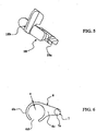
- a blocking slide 18, shown in more detail on the figure 5 has a distal end 18a shaped to engage in the transverse notches 17 of the longitudinal connecting rod 7a.
- the locking slide 18 is intended to be mounted in a housing 8b of the guide support 8 to slide laterally towards and away from the longitudinal connecting rod 7a between a locking position in which its distal end 18a is engaged in a transversal notch 17 of the longitudinal connecting rod 7a and a release position in which the distal end 18a of the locking slide 18 is away from the longitudinal connecting rod 7a.
- a helical spring 19 is provided to permanently return the locking slide 18 in its locking position.
- the blocking slide 18 comprises gripping means 18b by a user. As illustrated on the figure 1 , the gripping means 18b allow the user to operate the blocking slide 18 in translation in the direction and direction defined by the arrow 20. The blocking slide 18 is thus operated from its blocking position to its release position against the restoring force exerted by the helical spring 19.
- the distal end 18a is then withdrawn away from the transverse detents 17 of the longitudinal connecting rod 7a which can then be moved in the guide sleeve 8a in a movement bilateral translation illustrated by the double arrow 21 to adjust the penetration depth P of the drill 1.
- the locking slide 18 is returned to its locking position by the helical spring 19 to maintain the chosen penetration depth P.
- the guide sleeve 8a has an internal bore 80a of complementary cross section in the form of the cross section of the longitudinal connecting rod 7a.
- the cross sections of the longitudinal connecting rod 7a and the internal bore 80a of the guide sleeve 8a prevent any relative rotational movement therebetween.
- the cross section of the longitudinal connecting rod 7a is circular with a flat.
Landscapes
- Health & Medical Sciences (AREA)
- Oral & Maxillofacial Surgery (AREA)
- Dentistry (AREA)
- Epidemiology (AREA)
- Life Sciences & Earth Sciences (AREA)
- Animal Behavior & Ethology (AREA)
- General Health & Medical Sciences (AREA)
- Public Health (AREA)
- Veterinary Medicine (AREA)
- Engineering & Computer Science (AREA)
- Biomedical Technology (AREA)
- Neurology (AREA)
- Neurosurgery (AREA)
- Nuclear Medicine, Radiotherapy & Molecular Imaging (AREA)
- Surgery (AREA)
- Dental Tools And Instruments Or Auxiliary Dental Instruments (AREA)
Claims (11)
- Zahnärztliches Handstück, das es erlaubt, einen Bohrer (1, 12) zu halten und in Bewegung relativ zu einer Richtung des Eindringens (I-I) anzutreiben, enthaltend:- einen Körper (2) mit einer proximalen Extremität (2a) und einer distalen Extremität (2b) des Körpers,- einen demontierbaren Kopf (3), der mit der distalen Extremität (2b) des Körpers verbunden ist und ausgebildet ist, den Bohrer (1, 12) zu halten,- Anschlagmittel (4), die durch Befestigungsmittel (5) am zahnärztlichen Handstück befestigt sind und gestatten, die Eindringtiefe des Bohrers (1, 12) in den Körper eines Patienten zu begrenzen,wobei die Anschlagmittel (4) enthalten:- einen Anschlagkörper (6) mit einer Anschlagfläche (6a), die ausgebildet ist, am Ende des Eindringens des Bohrers (1, 12) in den Körper des Patienten gegen den Körper des Patienten in Anschlag zu gelangen,- ein Verbindungsteil (7), das am Anschlagkörper (6) angebracht ist und sich in einer Richtung (II-II) erstreckt, die im wesentlichen senkrecht zur Anschlagfläche (6a) ist,- eine Führungshalterung (8), die an dem zahnärztlichen Handstück einen Vorsprung bildet und ausgebildet ist, das Verbindungsteil (7) zu halten und von dem mindestens ein vorspringender Abschnitt ein angesetztes Teil ist, das in lösbarer Weise an dem zahnärztlichen Handstück befestigt ist,dadurch gekennzeichnet, dass:- die Befestigungsmittel (5) eine Ausnehmung (90) aufweisen, die in dem zahnärztlichen Handstück ausgebildet ist,- die Befestigungsmittel (5) einen Vorsprung (100) aufweisen, der an den Anschlagmitteln (4) angebracht ist und dazu ausgebildet ist, in die Ausnehmung (90) einzudringen und in ihr gehalten zu werden,- das zahnärztliche Handstück Mittel zum Verriegeln (50) aufweist, die selektiv eine Trennung des Vorsprunges (100) und der Ausnehmung (90) verbieten und die durch die einzige Montagebewegung des Kopfes (3) gegenüber dem Körper (2) betätigt werden.
- Zahnärztliches Handstück nach Anspruch 1, dadurch gekennzeichnet, dass die Ausnehmung (90) in Nachbarschaft zu dem Kopf (3) ausgebildet ist und dazu eingerichtet ist, einen Eingriff des Vorsprunges (100) in einer Eingriffsrichtung (III-III) zu gestatten, die im wesentlichen senkrecht zur Eindringrichtung (I-I) ist und um jegliches Herausziehen des Vorsprunges (100) in jeder anderen Richtung als der Eingriffsrichtung (III-III) zu verbieten.
- Zahnärztliches Handstück nach einem der Ansprüche 1 oder 2, dadurch gekennzeichnet,
dass die Führungshalterung (8) vollständig von dem zahnärztlichen Handstück lösbar ist. - Zahnärztliches Handstück nach irgendeinem der Ansprüche 1 bis 3, dadurch gekennzeichnet,
dass:- der Kopf (3) in lösbarer Weise an der distalen Extremität (2b) des Körpers (2) befestigt ist, durch axialen Eingriff in die distale Extremität (2b) des Körpers (2),- die Ausnehmung (90) an dem Kopf (3) ausgebildet ist und axial in der Eingriffsrichtung (III-III) ausgerichtet ist und an ihrer proximalen Extremität (9a) offen ist,- die Mittel zum Verriegeln (50) eine Anschlagfacette (51) aufweisen, die an der distalen Extremität (2b) des Körpers (2) anbeordnet ist, die die proximale Extremität (9a) der Ausnehmung (90) füllt, wenn der Kopf (3) an den Körper (2) montiert ist,- der Vorsprung (100) der Fixationsmittel (5) sich längs einer Länge (L2) erstreckt, die gleich oder geringfügig kleiner als die Länge (L1) der Ausnehmung (90) ist. - Zahnärztliches Handstück nach irgendeinem der Ansprüche 1 bis 4, dadurch gekennzeichnet,
dass die Ausnehmung (90) eine Rille (9) ist und dass der Vorsprung (100) eine Rippe (10) ist. - Zahnärztliches Handstück nach Anspruch 5, dadurch gekennzeichnet,
dass die Rille (9) und die Rippe (10) trapezförmige Querschnitte mit komplementären Formen haben, die es erlauben, eine Montage mit einem Schwalbenschwanz auszuführen. - Zahnärztliches Handstück nach irgendeinem der Ansprüche 1 bis 6, dadurch gekennzeichnet,
dass:- das zahnärztliche Handstück Mittel zum Projektieren von Fluid (13) aufweist, die ausgebildet sind, ein Fluid in der Nähe der Arbeitszone des Bohrers (1, 12) zu projektieren mit mindestens einem Fluidstrahl, der im wesentlichen parallel zu dem Bohrer (1, 12) ist,- der Anschlagkörper (6) eine Beleuchtung (6d) aufweist, in Korrespondenz mit der Trajectorie des Fluidstrahles. - Zahnärztliches Handstück nach irgendeinem der Ansprüche 1 bis 7, dadurch gekennzeichnet, dass:- das Verbindungsteil (7) einen längs verlaufenden Verbindungsschaft (7a) aufweist,- die Führungshalterung (8) einen Führungsstutzen (8a) aufweist, in welchem der längs verlaufende Verbindungsschaft (7a) gleiten kann,- die Mittel zum Blockieren (16) es gestatten, jegliche Verschiebung des sich längs erstreckenden Verbindungsschaftes (7a) in dem Führungsstutzen (8a) zu unterbinden.
- Zahnärztliches Handstück nach Anspruch 8, dadurch gekennzeichnet, dass:- der Führungsstutzen (8a) eine innere Bohrung (80a) mit einem Querschnitt aufweist, der zur Form des Querschnittes des längs verlaufenden Verbindungsschaftes (7a) komplementär ist,- die Querschnitte des längs verlaufenden Verbindungsschaftes (7a) und der inneren Bohrung (80a) des Führungsstutzens (8a) jegliche relative Drehbewegung zwischen ihnen verhindern.
- Zahnärztliches Handstück nach einem der Ansprüche 8 oder 9, dadurch gekennzeichnet, dass die Mittel zum Blockieren (16) aufweisen:- eine Vielzahl von quer verlaufenden Rasten (17), die längs der Länge des sich längs erstreckenden Verbindungsschaftes (7a) verteilt sind,- einen Blockierschieber (18) an der distalen Extremität (18a), der ausgebildet ist, in die quer verlaufenden Rasten (17) des längs verlaufenden Verbindungsschaftes (7a) einzugreifen, und geeignet ist für ein seitliches Gleiten in Richtung und im Abstand zu dem sich längs erstreckenden Verbindungsschaftes (7a) in einem Sitz (8b) der Führungshalterung (8) zwischen einer Position des Blockierens, in welcher seine distale Extremität (18a) in der quer verlaufenden Raste (17) des längs verlaufenden Verbindungsschaftes (7a) in Eingriff steht und in einer Position der Freigabe, in welcher die distale Extremität (18a) des Blockierungsschiebers (18) im Abstand zu dem sich längs erstreckenden Führungsschaft (7a) ist.
- Zahnärztliches Handstück nach Anspruch 10,
dadurch gekennzeichnet, dass:- eine schraubenförmige Feder (19) den Blockierschieber (18) permanent in seine Position des Blockierens drückt,- der Blockierungsschieber (18) Greifmittel (18b) für einen Benutzer aufweist, die ihm gestatten, den Blockierschieber (18) aus seiner Position des Blockierens in eine Position der Freigabe zu manövrieren, gegen die Federkraft, die von der schraubenförmigen Feder (19) ausgeübt wird.
Applications Claiming Priority (2)
| Application Number | Priority Date | Filing Date | Title |
|---|---|---|---|
| FR0654131A FR2906707B1 (fr) | 2006-10-06 | 2006-10-06 | Piece a main dentaire a dispositif de butee |
| PCT/IB2007/054045 WO2008041198A1 (fr) | 2006-10-06 | 2007-10-04 | Piece a main dentaire a dispositif de butee |
Publications (2)
| Publication Number | Publication Date |
|---|---|
| EP2068744A1 EP2068744A1 (de) | 2009-06-17 |
| EP2068744B1 true EP2068744B1 (de) | 2012-05-02 |
Family
ID=38068400
Family Applications (1)
| Application Number | Title | Priority Date | Filing Date |
|---|---|---|---|
| EP07805444A Active EP2068744B1 (de) | 2006-10-06 | 2007-10-04 | Dentalhandstück mit widerlagervorrichtung |
Country Status (5)
| Country | Link |
|---|---|
| US (1) | US8109762B2 (de) |
| EP (1) | EP2068744B1 (de) |
| AT (1) | ATE555739T1 (de) |
| FR (1) | FR2906707B1 (de) |
| WO (1) | WO2008041198A1 (de) |
Families Citing this family (17)
| Publication number | Priority date | Publication date | Assignee | Title |
|---|---|---|---|---|
| FR2925289B1 (fr) * | 2007-12-20 | 2011-01-21 | Anthogyr Sa | Dispositif de centrage et de guidage d'un foret de piece a main dentaire |
| WO2010025191A1 (en) * | 2008-08-29 | 2010-03-04 | Zimmer Dental, Inc. | Dental drill guide system |
| CA2724093A1 (en) * | 2009-12-17 | 2011-06-17 | Straumann Holding Ag | Dental tools for guided surgery |
| FR2962896B1 (fr) * | 2010-07-26 | 2012-08-03 | Gerald Blouin | Accessoire de nettoyage pour systeme de vision et ensemble de nettoyage correspondant |
| US9468504B2 (en) | 2013-02-27 | 2016-10-18 | B & D Dental Corporation | Dental cutting system and method with remote cutting guide |
| USD708330S1 (en) * | 2013-03-07 | 2014-07-01 | DigitalPrep Technologies, Inc. | Dental handpiece |
| CN103169543B (zh) * | 2013-03-18 | 2015-10-28 | 李凤强 | 用于根管治疗仪的机用扩大针定位器 |
| USD713034S1 (en) * | 2013-05-03 | 2014-09-09 | DigitalPrep Technologies, Inc. | Dental handpiece |
| US10993729B1 (en) * | 2014-07-02 | 2021-05-04 | Insurgical, Inc. | Sterile ready-to-use surgical tool and attachment system |
| US20160000449A1 (en) * | 2014-07-02 | 2016-01-07 | Peter M. Aman | Sterile ready-to-use surgical tool and attachment system |
| US11896449B2 (en) * | 2016-11-19 | 2024-02-13 | Sohail M. Ebrahimi | Snapon adjustable implant surgical drill stop and surgical guide |
| US12402894B2 (en) * | 2019-08-14 | 2025-09-02 | Versah, LLC | Universal keyless guided surgery system |
| US20220114243A1 (en) | 2020-01-24 | 2022-04-14 | Alitheon, Inc. | Data control using digital fingerprints |
| US20210390285A1 (en) | 2020-06-16 | 2021-12-16 | Alitheon, Inc. | Temporal-spatial digital fingerprinting |
| US20220086008A1 (en) | 2020-09-15 | 2022-03-17 | Alitheon, Inc. | System for authenticating physical objects using digital fingerprints |
| US20230380891A1 (en) * | 2022-05-26 | 2023-11-30 | Biosense Webster (Israel) Ltd. | Port and depth stop and tip features for transseptal puncture apparatus |
| CN115252192B (zh) * | 2022-09-06 | 2023-09-22 | 江苏诺圣医疗科技有限公司 | 一种牙科种植机用定位装置 |
Family Cites Families (8)
| Publication number | Priority date | Publication date | Assignee | Title |
|---|---|---|---|---|
| DE1084870B (de) * | 1958-01-09 | 1960-07-07 | Dr Reinmar Binder | Vorrichtung zum maschinellen Aufbereiten der Wurzelkanaele von Zaehnen |
| US3346959A (en) * | 1964-02-25 | 1967-10-17 | David S Fridge | Dental paralleling handpiece |
| US3838517A (en) * | 1973-04-09 | 1974-10-01 | B Michnick | Combination depth stop and gauge assembly for a dental drill |
| US4571183A (en) * | 1982-10-06 | 1986-02-18 | Syntex (U.S.A.) Inc. | Vibratory endodontic device |
| JPS62201151A (ja) * | 1986-03-03 | 1987-09-04 | 株式会社中西歯科器械製作所 | 歯科処置工具の案内装置 |
| AT388283B (de) * | 1987-08-24 | 1989-05-26 | Buermoos Dentalwerk | Zahnaerztliches handstueck |
| DE19831568A1 (de) * | 1998-07-14 | 2000-01-20 | Kaltenbach & Voigt | Handstück für ärztliche oder zahnärztliche Zwecke mit einer einstellbaren Anschlagvorrichtung |
| FR2831050A1 (fr) | 2001-10-19 | 2003-04-25 | Anthogyr Sa | Piece a main equipee d'une butee de profondeur pour les operations de percage |
-
2006
- 2006-10-06 FR FR0654131A patent/FR2906707B1/fr not_active Expired - Fee Related
-
2007
- 2007-10-04 WO PCT/IB2007/054045 patent/WO2008041198A1/fr not_active Ceased
- 2007-10-04 EP EP07805444A patent/EP2068744B1/de active Active
- 2007-10-04 US US12/444,175 patent/US8109762B2/en active Active
- 2007-10-04 AT AT07805444T patent/ATE555739T1/de active
Also Published As
| Publication number | Publication date |
|---|---|
| US8109762B2 (en) | 2012-02-07 |
| ATE555739T1 (de) | 2012-05-15 |
| US20100047737A1 (en) | 2010-02-25 |
| FR2906707B1 (fr) | 2009-11-06 |
| EP2068744A1 (de) | 2009-06-17 |
| WO2008041198A1 (fr) | 2008-04-10 |
| FR2906707A1 (fr) | 2008-04-11 |
Similar Documents
| Publication | Publication Date | Title |
|---|---|---|
| EP2068744A1 (de) | Dentalhandstück mit widerlagervorrichtung | |
| EP2222243B1 (de) | Vorrichtung zur zentrierung und führung einer bohrkrone eines zahnärztlichen handinstruments | |
| EP2548535B1 (de) | Chirurgisches Instrument zur Entfernung einer Prothese | |
| EP2023840B1 (de) | Dynamometrisches werkzeug zur medizinischen verwendung | |
| FR2801189A1 (fr) | Implant pour raccourcissement osseux, et en particulier, metatarsien | |
| FR2861574A1 (fr) | Systeme de raccordement pour instrument chirurgical | |
| EP2047879A1 (de) | Sicherheitseinrichtung für eine Spritzvorrichtung | |
| EP2865353A1 (de) | Zahnprothesenanordnung, die ein Zahnimplantat und eine feste Zahnprothese umfasst | |
| EP3419530B1 (de) | Vorrichtung zur sterilen kopplung eines perkutanen chirurgischen instruments und antriebswerkzeug und verfahren zur durchführung solch einer kopplung | |
| EP1675523A1 (de) | Handstück für zahnmedizinische oder chirurgische verwendung mit arretiermechanismus | |
| WO2010061124A1 (fr) | Dispositif d'aide a la pose d'implants dentaires | |
| FR3041239A1 (fr) | Dispositif pour le couplage sterile d'un instrument chirurgical percutane et d'un outil d'entrainement et methode pour realiser un tel couplage | |
| FR3033692A1 (fr) | Prothese dentaire plurale transfixee | |
| EP1642541B1 (de) | Vorrichtung zur Entnahme und Implantation von Haartransplantat | |
| WO2008034980A1 (fr) | Contre-angle tournevis universel pour implantologie | |
| WO2008007018A1 (fr) | Dispositif de butee reglable pour instrument de dentisterie | |
| CH666804A5 (fr) | Tete de contre-angle ou de turbine d'une piece a main dentaire. | |
| WO2012010794A1 (fr) | Implant dentaire et dispositif d'entrainement en rotation dudit implant dentaire | |
| FR2913327A1 (fr) | Instrument de guidage orthopedique, broche et procede | |
| EP3868327B1 (de) | Anordnung für die geführte dentalchirurgie | |
| FR3079131A1 (fr) | Dispositif d'assistance au forage d'un puits pour implant dentaire | |
| CH632145A5 (fr) | Piece a main dentaire. | |
| FR3125735A1 (fr) | Porte-outil pour outil modulaire | |
| EP3431034B1 (de) | Unterelement für zahnärztliches oder chirurgisches handstück, zahnärztliches oder chirurgisches handstück und entsprechendes montageverfahren | |
| EP3763317B1 (de) | Bohrschablone für dentale implantologie |
Legal Events
| Date | Code | Title | Description |
|---|---|---|---|
| PUAI | Public reference made under article 153(3) epc to a published international application that has entered the european phase |
Free format text: ORIGINAL CODE: 0009012 |
|
| 17P | Request for examination filed |
Effective date: 20090331 |
|
| AK | Designated contracting states |
Kind code of ref document: A1 Designated state(s): AT BE BG CH CY CZ DE DK EE ES FI FR GB GR HU IE IS IT LI LT LU LV MC MT NL PL PT RO SE SI SK TR |
|
| GRAP | Despatch of communication of intention to grant a patent |
Free format text: ORIGINAL CODE: EPIDOSNIGR1 |
|
| DAX | Request for extension of the european patent (deleted) | ||
| GRAS | Grant fee paid |
Free format text: ORIGINAL CODE: EPIDOSNIGR3 |
|
| GRAA | (expected) grant |
Free format text: ORIGINAL CODE: 0009210 |
|
| AK | Designated contracting states |
Kind code of ref document: B1 Designated state(s): AT BE BG CH CY CZ DE DK EE ES FI FR GB GR HU IE IS IT LI LT LU LV MC MT NL PL PT RO SE SI SK TR |
|
| REG | Reference to a national code |
Ref country code: GB Ref legal event code: FG4D Free format text: NOT ENGLISH |
|
| REG | Reference to a national code |
Ref country code: AT Ref legal event code: REF Ref document number: 555739 Country of ref document: AT Kind code of ref document: T Effective date: 20120515 Ref country code: CH Ref legal event code: EP |
|
| REG | Reference to a national code |
Ref country code: IE Ref legal event code: FG4D Free format text: LANGUAGE OF EP DOCUMENT: FRENCH |
|
| REG | Reference to a national code |
Ref country code: DE Ref legal event code: R096 Ref document number: 602007022468 Country of ref document: DE Effective date: 20120628 |
|
| REG | Reference to a national code |
Ref country code: CH Ref legal event code: NV Representative=s name: ZIMMERLI, WAGNER & PARTNER AG |
|
| REG | Reference to a national code |
Ref country code: NL Ref legal event code: VDEP Effective date: 20120502 |
|
| REG | Reference to a national code |
Ref country code: LT Ref legal event code: MG4D Effective date: 20120502 |
|
| PG25 | Lapsed in a contracting state [announced via postgrant information from national office to epo] |
Ref country code: SE Free format text: LAPSE BECAUSE OF FAILURE TO SUBMIT A TRANSLATION OF THE DESCRIPTION OR TO PAY THE FEE WITHIN THE PRESCRIBED TIME-LIMIT Effective date: 20120502 Ref country code: PL Free format text: LAPSE BECAUSE OF FAILURE TO SUBMIT A TRANSLATION OF THE DESCRIPTION OR TO PAY THE FEE WITHIN THE PRESCRIBED TIME-LIMIT Effective date: 20120502 Ref country code: LT Free format text: LAPSE BECAUSE OF FAILURE TO SUBMIT A TRANSLATION OF THE DESCRIPTION OR TO PAY THE FEE WITHIN THE PRESCRIBED TIME-LIMIT Effective date: 20120502 Ref country code: FI Free format text: LAPSE BECAUSE OF FAILURE TO SUBMIT A TRANSLATION OF THE DESCRIPTION OR TO PAY THE FEE WITHIN THE PRESCRIBED TIME-LIMIT Effective date: 20120502 Ref country code: CY Free format text: LAPSE BECAUSE OF FAILURE TO SUBMIT A TRANSLATION OF THE DESCRIPTION OR TO PAY THE FEE WITHIN THE PRESCRIBED TIME-LIMIT Effective date: 20120502 Ref country code: IS Free format text: LAPSE BECAUSE OF FAILURE TO SUBMIT A TRANSLATION OF THE DESCRIPTION OR TO PAY THE FEE WITHIN THE PRESCRIBED TIME-LIMIT Effective date: 20120902 |
|
| PG25 | Lapsed in a contracting state [announced via postgrant information from national office to epo] |
Ref country code: LV Free format text: LAPSE BECAUSE OF FAILURE TO SUBMIT A TRANSLATION OF THE DESCRIPTION OR TO PAY THE FEE WITHIN THE PRESCRIBED TIME-LIMIT Effective date: 20120502 Ref country code: SI Free format text: LAPSE BECAUSE OF FAILURE TO SUBMIT A TRANSLATION OF THE DESCRIPTION OR TO PAY THE FEE WITHIN THE PRESCRIBED TIME-LIMIT Effective date: 20120502 Ref country code: GR Free format text: LAPSE BECAUSE OF FAILURE TO SUBMIT A TRANSLATION OF THE DESCRIPTION OR TO PAY THE FEE WITHIN THE PRESCRIBED TIME-LIMIT Effective date: 20120803 Ref country code: PT Free format text: LAPSE BECAUSE OF FAILURE TO SUBMIT A TRANSLATION OF THE DESCRIPTION OR TO PAY THE FEE WITHIN THE PRESCRIBED TIME-LIMIT Effective date: 20120903 |
|
| PG25 | Lapsed in a contracting state [announced via postgrant information from national office to epo] |
Ref country code: DK Free format text: LAPSE BECAUSE OF FAILURE TO SUBMIT A TRANSLATION OF THE DESCRIPTION OR TO PAY THE FEE WITHIN THE PRESCRIBED TIME-LIMIT Effective date: 20120502 Ref country code: CZ Free format text: LAPSE BECAUSE OF FAILURE TO SUBMIT A TRANSLATION OF THE DESCRIPTION OR TO PAY THE FEE WITHIN THE PRESCRIBED TIME-LIMIT Effective date: 20120502 Ref country code: NL Free format text: LAPSE BECAUSE OF FAILURE TO SUBMIT A TRANSLATION OF THE DESCRIPTION OR TO PAY THE FEE WITHIN THE PRESCRIBED TIME-LIMIT Effective date: 20120502 Ref country code: EE Free format text: LAPSE BECAUSE OF FAILURE TO SUBMIT A TRANSLATION OF THE DESCRIPTION OR TO PAY THE FEE WITHIN THE PRESCRIBED TIME-LIMIT Effective date: 20120502 Ref country code: SK Free format text: LAPSE BECAUSE OF FAILURE TO SUBMIT A TRANSLATION OF THE DESCRIPTION OR TO PAY THE FEE WITHIN THE PRESCRIBED TIME-LIMIT Effective date: 20120502 Ref country code: RO Free format text: LAPSE BECAUSE OF FAILURE TO SUBMIT A TRANSLATION OF THE DESCRIPTION OR TO PAY THE FEE WITHIN THE PRESCRIBED TIME-LIMIT Effective date: 20120502 |
|
| PG25 | Lapsed in a contracting state [announced via postgrant information from national office to epo] |
Ref country code: IT Free format text: LAPSE BECAUSE OF FAILURE TO SUBMIT A TRANSLATION OF THE DESCRIPTION OR TO PAY THE FEE WITHIN THE PRESCRIBED TIME-LIMIT Effective date: 20120502 |
|
| PLBE | No opposition filed within time limit |
Free format text: ORIGINAL CODE: 0009261 |
|
| STAA | Information on the status of an ep patent application or granted ep patent |
Free format text: STATUS: NO OPPOSITION FILED WITHIN TIME LIMIT |
|
| 26N | No opposition filed |
Effective date: 20130205 |
|
| BERE | Be: lapsed |
Owner name: ANTHOGYR Effective date: 20121031 |
|
| PG25 | Lapsed in a contracting state [announced via postgrant information from national office to epo] |
Ref country code: ES Free format text: LAPSE BECAUSE OF FAILURE TO SUBMIT A TRANSLATION OF THE DESCRIPTION OR TO PAY THE FEE WITHIN THE PRESCRIBED TIME-LIMIT Effective date: 20120813 |
|
| REG | Reference to a national code |
Ref country code: DE Ref legal event code: R097 Ref document number: 602007022468 Country of ref document: DE Effective date: 20130205 |
|
| PG25 | Lapsed in a contracting state [announced via postgrant information from national office to epo] |
Ref country code: MC Free format text: LAPSE BECAUSE OF NON-PAYMENT OF DUE FEES Effective date: 20121031 |
|
| GBPC | Gb: european patent ceased through non-payment of renewal fee |
Effective date: 20121004 |
|
| REG | Reference to a national code |
Ref country code: IE Ref legal event code: MM4A |
|
| PG25 | Lapsed in a contracting state [announced via postgrant information from national office to epo] |
Ref country code: BG Free format text: LAPSE BECAUSE OF FAILURE TO SUBMIT A TRANSLATION OF THE DESCRIPTION OR TO PAY THE FEE WITHIN THE PRESCRIBED TIME-LIMIT Effective date: 20120802 Ref country code: GB Free format text: LAPSE BECAUSE OF NON-PAYMENT OF DUE FEES Effective date: 20121004 Ref country code: IE Free format text: LAPSE BECAUSE OF NON-PAYMENT OF DUE FEES Effective date: 20121004 Ref country code: BE Free format text: LAPSE BECAUSE OF NON-PAYMENT OF DUE FEES Effective date: 20121031 |
|
| PG25 | Lapsed in a contracting state [announced via postgrant information from national office to epo] |
Ref country code: MT Free format text: LAPSE BECAUSE OF FAILURE TO SUBMIT A TRANSLATION OF THE DESCRIPTION OR TO PAY THE FEE WITHIN THE PRESCRIBED TIME-LIMIT Effective date: 20120502 |
|
| REG | Reference to a national code |
Ref country code: CH Ref legal event code: NV Representative=s name: WAGNER PATENT AG, CH |
|
| PG25 | Lapsed in a contracting state [announced via postgrant information from national office to epo] |
Ref country code: TR Free format text: LAPSE BECAUSE OF FAILURE TO SUBMIT A TRANSLATION OF THE DESCRIPTION OR TO PAY THE FEE WITHIN THE PRESCRIBED TIME-LIMIT Effective date: 20120502 |
|
| PG25 | Lapsed in a contracting state [announced via postgrant information from national office to epo] |
Ref country code: LU Free format text: LAPSE BECAUSE OF NON-PAYMENT OF DUE FEES Effective date: 20121004 |
|
| PG25 | Lapsed in a contracting state [announced via postgrant information from national office to epo] |
Ref country code: HU Free format text: LAPSE BECAUSE OF FAILURE TO SUBMIT A TRANSLATION OF THE DESCRIPTION OR TO PAY THE FEE WITHIN THE PRESCRIBED TIME-LIMIT Effective date: 20071004 |
|
| REG | Reference to a national code |
Ref country code: FR Ref legal event code: PLFP Year of fee payment: 9 |
|
| REG | Reference to a national code |
Ref country code: FR Ref legal event code: PLFP Year of fee payment: 10 |
|
| REG | Reference to a national code |
Ref country code: FR Ref legal event code: PLFP Year of fee payment: 11 |
|
| REG | Reference to a national code |
Ref country code: FR Ref legal event code: PLFP Year of fee payment: 12 |
|
| PGFP | Annual fee paid to national office [announced via postgrant information from national office to epo] |
Ref country code: DE Payment date: 20211020 Year of fee payment: 15 |
|
| REG | Reference to a national code |
Ref country code: DE Ref legal event code: R119 Ref document number: 602007022468 Country of ref document: DE |
|
| P01 | Opt-out of the competence of the unified patent court (upc) registered |
Effective date: 20230519 |
|
| PG25 | Lapsed in a contracting state [announced via postgrant information from national office to epo] |
Ref country code: DE Free format text: LAPSE BECAUSE OF NON-PAYMENT OF DUE FEES Effective date: 20230503 |
|
| REG | Reference to a national code |
Ref country code: CH Ref legal event code: U11 Free format text: ST27 STATUS EVENT CODE: U-0-0-U10-U11 (AS PROVIDED BY THE NATIONAL OFFICE) Effective date: 20251101 |
|
| PGFP | Annual fee paid to national office [announced via postgrant information from national office to epo] |
Ref country code: AT Payment date: 20251022 Year of fee payment: 19 |
|
| PGFP | Annual fee paid to national office [announced via postgrant information from national office to epo] |
Ref country code: FR Payment date: 20251029 Year of fee payment: 19 |
|
| PGFP | Annual fee paid to national office [announced via postgrant information from national office to epo] |
Ref country code: CH Payment date: 20251101 Year of fee payment: 19 |