EP2070059B1 - Alimentation directe de documents avec cassette amovible - Google Patents
Alimentation directe de documents avec cassette amovible Download PDFInfo
- Publication number
- EP2070059B1 EP2070059B1 EP07814667A EP07814667A EP2070059B1 EP 2070059 B1 EP2070059 B1 EP 2070059B1 EP 07814667 A EP07814667 A EP 07814667A EP 07814667 A EP07814667 A EP 07814667A EP 2070059 B1 EP2070059 B1 EP 2070059B1
- Authority
- EP
- European Patent Office
- Prior art keywords
- document
- bulk
- acceptor
- feeder module
- module
- Prior art date
- Legal status (The legal status is an assumption and is not a legal conclusion. Google has not performed a legal analysis and makes no representation as to the accuracy of the status listed.)
- Active
Links
Images






Classifications
-
- G—PHYSICS
- G07—CHECKING-DEVICES
- G07D—HANDLING OF COINS OR VALUABLE PAPERS, e.g. TESTING, SORTING BY DENOMINATIONS, COUNTING, DISPENSING, CHANGING OR DEPOSITING
- G07D11/00—Devices accepting coins; Devices accepting, dispensing, sorting or counting valuable papers
- G07D11/10—Mechanical details
- G07D11/14—Inlet or outlet ports
-
- G—PHYSICS
- G07—CHECKING-DEVICES
- G07D—HANDLING OF COINS OR VALUABLE PAPERS, e.g. TESTING, SORTING BY DENOMINATIONS, COUNTING, DISPENSING, CHANGING OR DEPOSITING
- G07D11/00—Devices accepting coins; Devices accepting, dispensing, sorting or counting valuable papers
- G07D11/40—Device architecture, e.g. modular construction
-
- B—PERFORMING OPERATIONS; TRANSPORTING
- B65—CONVEYING; PACKING; STORING; HANDLING THIN OR FILAMENTARY MATERIAL
- B65H—HANDLING THIN OR FILAMENTARY MATERIAL, e.g. SHEETS, WEBS, CABLES
- B65H2301/00—Handling processes for sheets or webs
- B65H2301/30—Orientation, displacement, position of the handled material
- B65H2301/31—Features of transport path
- B65H2301/312—Features of transport path for transport path involving at least two planes of transport forming an angle between each other
- B65H2301/3123—S-shaped
-
- B—PERFORMING OPERATIONS; TRANSPORTING
- B65—CONVEYING; PACKING; STORING; HANDLING THIN OR FILAMENTARY MATERIAL
- B65H—HANDLING THIN OR FILAMENTARY MATERIAL, e.g. SHEETS, WEBS, CABLES
- B65H2403/00—Power transmission; Driving means
- B65H2403/90—Machine drive
- B65H2403/94—Other features of machine drive
- B65H2403/942—Bidirectional powered handling device
-
- B—PERFORMING OPERATIONS; TRANSPORTING
- B65—CONVEYING; PACKING; STORING; HANDLING THIN OR FILAMENTARY MATERIAL
- B65H—HANDLING THIN OR FILAMENTARY MATERIAL, e.g. SHEETS, WEBS, CABLES
- B65H2404/00—Parts for transporting or guiding the handled material
- B65H2404/60—Other elements in face contact with handled material
- B65H2404/63—Oscillating, pivoting around an axis parallel to face of material, e.g. diverting means
- B65H2404/632—Wedge member
-
- B—PERFORMING OPERATIONS; TRANSPORTING
- B65—CONVEYING; PACKING; STORING; HANDLING THIN OR FILAMENTARY MATERIAL
- B65H—HANDLING THIN OR FILAMENTARY MATERIAL, e.g. SHEETS, WEBS, CABLES
- B65H2405/00—Parts for holding the handled material
- B65H2405/30—Other features of supports for sheets
- B65H2405/33—Compartmented support
- B65H2405/332—Superposed compartments
- B65H2405/3322—Superposed compartments discharge tray superposed to feed tray
-
- Y—GENERAL TAGGING OF NEW TECHNOLOGICAL DEVELOPMENTS; GENERAL TAGGING OF CROSS-SECTIONAL TECHNOLOGIES SPANNING OVER SEVERAL SECTIONS OF THE IPC; TECHNICAL SUBJECTS COVERED BY FORMER USPC CROSS-REFERENCE ART COLLECTIONS [XRACs] AND DIGESTS
- Y10—TECHNICAL SUBJECTS COVERED BY FORMER USPC
- Y10T—TECHNICAL SUBJECTS COVERED BY FORMER US CLASSIFICATION
- Y10T29/00—Metal working
- Y10T29/49—Method of mechanical manufacture
- Y10T29/49002—Electrical device making
-
- Y—GENERAL TAGGING OF NEW TECHNOLOGICAL DEVELOPMENTS; GENERAL TAGGING OF CROSS-SECTIONAL TECHNOLOGIES SPANNING OVER SEVERAL SECTIONS OF THE IPC; TECHNICAL SUBJECTS COVERED BY FORMER USPC CROSS-REFERENCE ART COLLECTIONS [XRACs] AND DIGESTS
- Y10—TECHNICAL SUBJECTS COVERED BY FORMER USPC
- Y10T—TECHNICAL SUBJECTS COVERED BY FORMER US CLASSIFICATION
- Y10T29/00—Metal working
- Y10T29/49—Method of mechanical manufacture
- Y10T29/49718—Repairing
- Y10T29/49721—Repairing with disassembling
Definitions
- Banknote validators that accept banknotes in bulk can be incorporated, for example, into table-top counting machines or integral systems such as deposit automatic teller machines (ATMs). Such machines typically are designed initially to process bundles of banknotes. Some bill validators arc designed to handle one bill at a time.
- ATMs deposit automatic teller machines
- US 2005/0116407 relates to a paper sheets processor. Different paper sheets such as banknotes and paper moneys are inserted into a plurality of insertion parts. The paper sheets inserted into the respective insertion parts are run out one by one, and carried on the same carrying route. The run-out paper sheet is judged during the carriage thereof. According to the judgment result, a carrying destination thereof is determined, and then the paper sheet is carried and accommodated into the determined carrying destination.
- Different paper sheets such as banknotes and paper moneys are inserted into a plurality of insertion parts.
- the paper sheets inserted into the respective insertion parts are run out one by one, and carried on the same carrying route.
- the run-out paper sheet is judged during the carriage thereof. According to the judgment result, a carrying destination thereof is determined, and then the paper sheet is carried and accommodated into the determined carrying destination.
- the present disclosure relates, in one aspect, to an apparatus that includes a bulk document feeder module adapted for connection to a document acceptor.
- the bulk document feeder module is operable, when attached to the document acceptor, to feed one document at a time, from a bundle of documents, to the document acceptor.
- the bulk document feeder module can include a document transport mechanism, a portion of which includes a removable cartridge.
- the cartridge can be removable, for example, to enable clearing of a jam in a document path.
- the apparatus can include a tray to receive a bundle of documents.
- the tray can be mounted adjacent a front of the bulk document feeder, which is operable to strip one document at a time from the bundle of documents in the tray and to feed the stripped document to the document acceptor.
- the bulk document feeder module is mechanically and electrically connected to the document acceptor and includes first and second document paths, a transport mechanism to move a document along one of the document paths depending on whether the document is traveling through the bulk document feeder module in a first direction or a second direction, one or more sensors to detect a status of a document in the bulk document feeder module, and a processor to communicate with the document acceptor, to monitor the sensors, and to control the transport mechanism.
- the bulk document feeder module also includes a diverter having a first position and a second position. When a document is transported in the first direction through the bulk note feeder module, the diverter is operable to move to the second position, and when a document is transported in the second direction, the diverter remains in the first position.
- the diverter can form part of the removable cartridge.
- a related aspect is for a method of upgrading a document validator.
- the method includes attaching a bulk document feeder module to the document validator, and mechanically and electrically connecting the bulk document feeder module to an acceptor unit of the document validator.
- the method includes replacing a harness connecting the document validator to a host system to provide power and communication lines to the bulk document feeder module.
- the method also can include removing a bezel adjacent a document entry of the acceptor unit and mounting an input/output tray adjacent a document entry of the bulk document feeder module.
- Another related aspect is for a method of clearing a jam in a bulk document feeder module connected to a document acceptor module installed in safe.
- the method includes detaching a document input tray, withdrawing a removable cartridge from the bulk document feeder module through an opening in a wall of the safe, clearing a jammed object from the bulk document feeder module, and re-installing the cartridge and the input tray in place in a reversed sequence.
- an apparatus in another aspect, includes a document validator operable to detect automatically whether a bulk document feeder module is coupled to the document validator.
- the validator is operable to operate the bulk document feeder module if it detects one and is adapted to operate as a stand-alone document validator if not.
- an apparatus includes a bulk document feeder module that includes a document separator having a tensioned belt operable to contact an idler wheel when no document is present and having a high-friction wheel. Friction of the high-friction wheel on one side of a document is higher than the friction of the belt on the other side of the document when a document is present between the belt and the wheel.
- the present disclosure relates to a document handling apparatus that includes a bulk document feeder module with a removable cartridge.
- the module is retrofitable to be adapted to a standard bill validator so that, with minimum change to the original validator, notes can be fed from a bundle into the validator, which then processes the notes one at a time.
- the present disclosure facilitates adapting a bulk document feeder module to an existing MEI, Inc. Cashflow series validator unit.
- banknotes are used as an example of documents with which the bulk feeder module can be used.
- the module can be used with other types of documents as well, including, for example, printed coupons, intended to be processed by the acceptor module.
- the term "document” includes a substantially flat sheet of value including, but not limited to, banknotes, bank drafts, bills, checks, paper currency, security documents, printed coupons and other similar paper objects of value.
- a "bundle" of banknotes or other documents is not meant to imply that the banknotes or other documents are fastened together. Rather, a bundle of banknotes or other documents includes any pile of banknotes or other documents stacked one atop another.
- the validator unit includes an acceptor module 3 with control means (e.g., a microprocessor) and validation means (e.g., sensors and associated circuitry), as well as a cash box (sometimes referred to as a cassette) 4 with a stacker mechanism, all of which may be installed in a chassis 5.
- control means e.g., a microprocessor
- validation means e.g., sensors and associated circuitry
- a cash box sometimes referred to as a cassette
- stacker mechanism e.g., stacker mechanism
- a validator unit In a typical installation of the retail industry, for example, a validator unit often is installed in a safe, and bills are inserted one-by-one through a bezel (not shown) attached to the door that leads the bill to the validator unit.
- the safe includes a host system that manages the operation of the safe to which the bill validator is connected.
- the safe is a generally secure enclosure that includes a secure access door and may contain several bill acceptors with or without a bulk feeder (described below).
- One aspect of the disclosure addresses replacing the standard bezel for the validator unit with a tray that facilitates feeding a bulk of banknotes into the validator unit one note at a time.
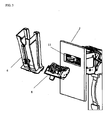
- a tray 6 replaces the standard bezel attached to the door 1 of the safe, and a bulk feeder module 7 (see FIG. 2B ) is mounted behind the door, between the original validator unit and the door.
- the bulk feeder module 7 is connected to the standard bezel connector and the validator unit mechanically and electrically.
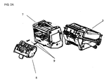
- FIG. 2A Another aspect of the disclosure addresses removal of jammed bills by providing a removable portion of the bill path in the form of a cartridge 8 (see FIG. 2A ) that comprises part of the transport mechanism of the bulk feeder module 7.
- the cartridge 8 can be made sufficiently small that it can be removed through a small opening 11 of the door 1 or a wall of a safe (see FIG. 3 ), while maintaining the cash stored in the cash box 4 secured within the safe, without having to open the door of the safe.
- the opening 11 is smaller than the validator unit or the acceptor module 3 so that they cannot be removed from the safe through the opening. Removal of the cartridge allows a jammed document to be cleared by an operator who does not have the authority to open the door to the safe.
- the input tray 6 has two levels that define two bins.
- the lower bin 12 is for an input bundle of notes and the upper bin 13 is for rejected notes.
- the notes are manually deposited in, or withdrawn from, the appropriate bin by an operator such as a cashier.
- a rotatable protective cover can be included over the upper bin 13 to reduce the likelihood of removal of notes by unauthorized persons.
- the bulk feeder module 7 includes control means comprising a microprocessor and sensors, as well as driving circuitry for a transport motor (see FIG. 16 ), and a set of light emitting diodes (LEDs) and a buzzer to provide a human-machine interface that also includes means (e.g., keypad) for entering information.
- control means comprising a microprocessor and sensors, as well as driving circuitry for a transport motor (see FIG. 16 ), and a set of light emitting diodes (LEDs) and a buzzer to provide a human-machine interface that also includes means (e.g., keypad) for entering information.
- the bulk feeder module 7 is connected to the acceptor module 3 via an electric connection that provides power to the module and a serial communication link (RS232) coupled to the processor in the acceptor module.
- RS232 serial communication link
- the synchronized operation of the bulk feeder with the validator unit is achieved via a communication protocol between the control means (e.g., microprocessor) in the bulk feeder module 7 and control means (e.g., microprocessor) of the acceptor module.
- the acceptor module 3 serving as the master unit, transmits commands to the bulk note feeder 7, and the bulk note feeder (serving as the slave unit) responds.
- the bulk note feeder 7 includes a processor for communicating with the acceptor module, for monitoring its sensors, and for controlling its motor.
- the motor in the bulk note feeder module 7 has a tachometric wheel for monitoring the distance a note travels.
- the bulk note feeder 7 has three sensors: a first (bunch) sensor 20 for detecting the presence of a bundle of notes, a second (reject) sensor 21 for detecting the progress of a note being rejected (returned), and a third (progress) sensor 22 for monitoring the transport of a note through the bulk note feeder.
- the sensors 20, 21, 22 are used to monitor the position of the banknote along the document path in the bulk feeder module 7.
- the reject sensor 21, in combination with the start sensor 20, also is used to detect the presence or absence of the cartridge 8.
- the sensors can be implemented, for example, as optical sensors using prisms and light pipes, light sources and corresponding detectors.
- the general mode of operation of the sensors is based upon continuity of an optical path that is disrupted when the cartridge 8 is removed or when a document intersects the optical beam.
- the sensors are operated under control of the processor in the control means of the feeder module 7, and their status is communicated to the control means of the acceptor unit 3 upon request from the acceptor unit's control means.
- the acceptor module 3 continuously polls the bulk note feeder 7 to retrieve the status of the various sensors 20, 21, 22 and the motor.
- the bulk note feeder module 7 has at least the following two operating modes: an accept document mode and a reject document mode.
- the process of accepting a document begins when a bundle of notes is inserted into, or placed on, the input bin 12 of tray 6.
- the acceptor module 3 communicates with the bulk note feeder 7 and, through a polling process of the sensors, detects that the bunch sensor 20 has been activated. When that happens, the acceptor module 3 starts its transport motor and commands the bulk note feeder 7 to turn on its motor. This causes a note to be stripped from the bundle in the tray 6 and fed through the bulk note feeder 7 into the acceptor module 3. Any subsequent note is prevented from moving past the acceptor module's start sensor (that is, a subsequent note is prevented from entering the acceptor module) by turning off the bulk note feeder's motor.
- the stripped note continues to travel through the acceptor module 3, which checks and determines the note's denomination and authenticity, and is transported to the acceptor module's escrow position where it is processed and then accepted for movement into the cassette 4 or returned via the bulk note feeder's reject path according to a command from the host system. If the note is accepted and additional notes are present in the bulk note feeder 7, then the acceptor module 3 turns on its transport motor and commands the bulk note feeder 7 to turn on its motor. A note staged at the acceptor module's start sensor is brought into the acceptor module; at that time, any subsequent notes are prevented from entering the acceptor module.
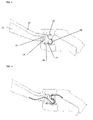
- FIG. 6 shows the path of the note inserted in the bulk feeder 7 going to the acceptor unit 3.
- the bulk feeder 7 includes a passive diverter 15 (see FIGS. 4 , 9 and 10 ) to direct rejected notes to the reject bin 13 of the input/output tray 6.
- the diverter can be active or tensioned.
- the diverter 15 When at rest, the diverter 15 is in a reject position, and is lifted by an incoming note to configure the document path to feed the note to the acceptor unit 3.
- the diverter 15 returns to the rest position by gravity once the note has cleared the location.
- the diverter 15 is attached to the removable cartridge 8. When a note is rejected, it is returned back through the entry slot of the acceptor module 3, and the diverter 15 configures the document path to return the note to the reject bin 13.
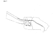
- FIG. 7 shows the path of a rejected note being returned.
- the acceptor module 3 commands the bulk note feeder 7 to turn on its motor in reverse for a short distance or until the progress sensor 22 becomes clear. This ensures that any note in the bulk note feeder 7 has moved back away from the diverter gate 15. This allows the diverter gate 15 to drop, thereby opening the bulk note feeder's reject path.
- the acceptor module 3 then turns on its transport motor in reverse and commands the bulk note feeder 7 to turn on its own motor in reverse so that the note is returned via the bulk note feeder's reject path.
- the bulk note feeder's reject sensor 21 is used to monitor the progress of the rejected note.
- the bulk note feeder module 7 includes a document transport mechanism.
- one end of the bundle of notes is lifted against a feeder pulley 19 by a feeder pinch arm 14 (see FIG. 4 ).
- the feeder pinch arm 14 applies pressure when notes are inserted into the tray 6 and retracts when the module 7 is in the note reject mode and when the input tray is emptied.
- the feeder pulley 19 pulls the banknote on top of the stack using friction.
- the note(s) is fed between a high friction drive pulley 18 and one or more stripper belts 17.
- the stripper belts are tensioned by a belt tensioner 16 which prevents any other notes from sticking to the top banknote.
- the high friction pulley 18 maximizes the traction on the top note while the belts 17 act like a band brake resisting the movement with lower friction on the opposite side of the document.
- the friction differential allows multiple notes to be separated while allowing the top note to move forward along the transport path.
- the diverter gate 15 FIGS. 4 , 9 and 10
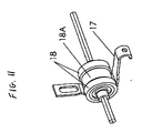
- the banknote separator includes two drive points on a drum-like arrangement.
- One such drive point is shown in FIG. 11 .
- the belt 17 is either stationary and under tension, as in the preferred implementation, or may be driven backwards in an alternate implementation.
- the feeder pulley 19 intermittently or continuously pushes the bundle into the high friction wheel and belt interface.
- the higher friction of the drive wheel 18 relative to the friction of the belt 17 allows the drive wheel to drive a document around the drum.
- the friction of the belt 17 in relation to the friction of the documents allows the belt to prevent forward movement of any additional documents that are in contact with the belt when a previous document is currently occupying the drive wheel.
- An idler wheel 18A, or sleeve keeps the belt 17 relatively tangent to the drive wheels 18 in order to provide a good pinch point for drawing the documents in.
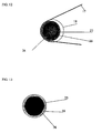
- the idler wheel 25 is mounted on an eccentric section of the drum arrangement. This causes the belt 17 to vibrate the bundle and eases the separation of sticky banknotes.
- the vibration of the idler wheel 25 and the belt 17 is achieved by a non-circular, substantially polygonal-like shaft spinning in a non-circular, substantially polygonal-like sleeve on the idler wheel.
- the idler wheel 25 is maintained idle by the friction of the belt 17.
- the idler wheel spins with the shaft.
- the bulk note feeder 7 also includes circuitry to produce an audible alarm and includes a green (or other color) LED that, under control of the acceptor module 3, indicate various conditions of the system. Such conditions include whether or not the system is enabled, whether or not the cassette or cartridge is installed, whether a fault was detected, or whether a banknote jam exists.
- the tray 6 is installed into openings in the door or outer wall 1 of the safe (see FIG. 3 ) because it allows easy access to other elements of the system such as the cartridge 8 and provides easy access to clear a jam and to perform other maintenance service in the bulk note feeder module without opening the safe. In that case, it is desirable to provide openings large enough to insert a banknote, but not too large to prevent unauthorized access to cash through these openings.
- the tray can be connected to apertures located in a wall inside of the safe other than the door or outside walls or an aperture in a bracket connected to the bulk note feeder module.
- a standard note acceptor unit may include a connector designed to provide power and control lines to an active bezel that includes, for example, flashing LEDs.
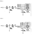
- a pin allocation of an MEI Cashflow SC66/83 bill validator unit is illustrated in FIG. 14 .
- the four lines labeled OEM_BEZEL_n can be reconfigured for the bulk note feeder module 7 as illustrated in FIG. 15 .
- pins 1 and 2 can be used to provide power
- pins 3 and 4 can be used for transmitting and receiving data (TXD and RXD) of a universal asynchronous receiver/transmitter (UART) for the serial communication between the bulk feeder 7 and the acceptor module 3.
- TXD and RXD universal asynchronous receiver/transmitter
- the acceptor module 3 auto-detects the presence of the bulk note feeder. For example, in a particular implementation, when the bulk banknote feeder is powered up, it periodically transmits a synchronization character to the bill validator unit. When the bill validator unit detects the character, it completes the synchronization process, and communication between the two devices begins. If the bulk note feeder 7 is not attached to the acceptor module 3, the acceptor module operates as a standard bill acceptor. The acceptor module 3 preferably maintains a copy of the bulk note feeder's processor code. When a bulk note feeder module 7 is detected, the acceptor module 3 verifies the processor's code for controlling the module and, if necessary, replaces it by downloading program code for the feeder module to memory in the module 7.
- the bulk note feeder 7 can be retrofitted in the field by replacing the system harness that connects the bill validator to the host system.
- the new harness routes the communication signals and power lines to the front bezel connector, as illustrated in FIG. 16 .
- the bulk note feeder 7 can be attached to the acceptor module 3 using two screws 9 or other mounting means (see FIG. 2 ).
- the communications cable 23 is attached between the acceptor module's front bezel connector and the bulk note feeder (see FIG. 5 ).
- the connection to the bezel connector, located at the front of the acceptor module 3, is convenient because of its proximity to the bulk note feeder 7, which implies a relatively short connection.
- the bulk note feeder 7 can be connected at the rear of the acceptor module 3 or at the rear of the interface module.
- Removing the cartridge 8 from the bulk note feeder 7 allows access to the bulk note feeder's note path for purposes of clearing any jammed notes.
- the input/output tray 6 is removed from the door 1 of the safe, and the cartridge 8 is detached and withdrawn from the feeder module 7 through the small opening 11 in the door or wall of the safe (see FIG. 3 ).
- the jammed object can be cleared from the bulk document feeder module, and the cartridge and the input tray are re-installed in place in a reversed sequence.
Landscapes
- Physics & Mathematics (AREA)
- General Physics & Mathematics (AREA)
- Sheets, Magazines, And Separation Thereof (AREA)
- Pile Receivers (AREA)
- Controlling Sheets Or Webs (AREA)
Claims (23)
- Appareil comprenant un module d'alimentation de documents en vrac adapté pour être connecté à un dispositif d'acceptation de documents, dans lequel le module d'alimentation de documents en vrac est capable de fonctionner, lorsqu'il est attaché au dispositif d'acceptation de documents, pour alimenter un document à la fois, depuis un paquet de documents, vers le dispositif d'acceptation de documents,
caractérisé en ce que le dispositif d'acceptation de documents comprend un processeur, et le module d'alimentation de documents en vrac comprend un processeur électriquement couplé au processeur du dispositif d'acceptation de documents. - Appareil selon la revendication 1, dans lequel le module d'alimentation de documents en vrac comprend un mécanisme de transport de documents, dont une portion inclut une cartouche amovible.
- Appareil selon la revendication 2, dans lequel la cartouche est amovible pour permettre de dégager un coincement dans un trajet de documents.
- Appareil selon la revendication 1, incluant des connexions électriques entre le module d'alimentation de documents en vrac et le dispositif d'acceptation de documents, dans lequel les connexions incluent des moyens pour fournir une puissance au module d'alimentation de documents en vrac et des moyens pour communiquer avec le module d'alimentation de documents en vrac
- Appareil selon la revendication 1, dans lequel le module d'alimentation de documents en vrac est capable de fonctionner pour faire office de module esclave du dispositif d'acceptation de documents, lequel est capable de fonctionner pour faire office de module maître.
- Appareil selon la revendication 1, dans lequel les moyens de communication sont capables de fonctionner en accord avec un protocole de communication série.
- Appareil selon la revendication 1, dans lequel le processeur du module d'alimentation de documents en vrac comprend un microprocesseur et une mémoire programme, et dans lequel le dispositif d'acceptation de documents est capable de fonctionner pour télécharger vers la mémoire programme un programme afin de commander le module d'alimentation de documents en vrac.
- Appareil selon la revendication 1, dans lequel le module d'alimentation de documents en vrac comprend une pluralité de capteurs pour détecter un état d'un document dans le trajet de documents.
- Appareil selon la revendication 8, dans lequel les capteurs comprennent des capteurs optiques.
- Appareil selon la revendication 2, dans lequel le mécanisme de transport de documents comprend un moteur qui est capable de fonctionner pour être mis en marche ou arrêté par un ordre du dispositif d'acceptation de documents.
- Appareil selon la revendication 1 ou 2, capable de fonctionner pour transporter un document en sens inverse si le document est rejeté par le dispositif d'acceptation de documents, dans lequel l'appareil inclut un plateau monté adjacent à une partie frontale du module d'alimentation de documents en vrac, le plateau ayant un premier réceptacle pour des documents à envoyer au dispositif d'acceptation de documents et un second réceptacle pour des documents rejetés par le dispositif d'acceptation de documents, et dans lequel le module d'alimentation de documents en vrac inclut un aiguillage pour envoyer les documents rejetés vers le réceptacle de rej et.
- Appareil selon la revendication 1 ou 2, comprenant un plateau pour recevoir un paquet de documents, dans lequel le plateau est monté adjacent à une partie frontale du module d'alimentation de documents en vrac, qui est capable de fonctionner pour isoler un document à la fois depuis le paquet de documents dans le plateau et pour alimenter le document isolé vers le dispositif d'acceptation de documents.
- Appareil selon la revendication 2, comprenant une chambre forte ayant une porte avec une ouverture, dans lequel le module d'alimentation de documents en vrac et le dispositif d'acceptation de documents sont situés à l'intérieur de la chambre forte, et dans lequel la cartouche est amovible à travers l'ouverture dans la porte de la chambre forte sans devoir ouvrir la porte.
- Appareil selon la revendication 13, dans lequel la taille de l'ouverture dans la porte de la chambre forte est suffisamment petite pour que ni le module d'alimentation de documents en vrac ni le dispositif d'acceptation de documents puisse être enlevé hors de la chambre forte à travers l'ouverture.
- Appareil selon les revendications 1 ou 2, dans lequel le module d'alimentation de documents en vrac est connecté mécaniquement et électriquement au dispositif d'acceptation de documents et comprend :un premier trajet de documents et un second trajet de documents,un mécanisme de transport pour déplacer un document le long de l'un des trajets de documents selon que le document circule à travers le module d'alimentation de documents en vrac dans une première direction ou dans une seconde direction,un ou plusieurs capteurs pour détecter un état d'un document dans le module d'alimentation de documents en vrac,un aiguillage ayant une première position et une seconde position telles que, quand un document est transporté dans la première direction à travers le module d'alimentation de documents en vrac l'aiguillage est capable de fonctionner pour se déplacer à la seconde position et, quand un document est transporté dans la seconde direction, l'aiguillage reste dans la première position, etun processeur pour communiquer avec le dispositif d'acceptation de documents, pour surveiller les capteurs, et pour commander le mécanisme de transport.
- Appareil selon la revendication 15, comprenant un plateau d'entrée/sortie détachable pour recevoir des documents, dans lequel le plateau est attaché adjacent à une entrée pour un trajet de documents dans le module d'alimentation de documents en vrac.
- Appareil selon la revendication 16, dans lesquels le premier trajet de documents est destiné au transport d'un document depuis un réceptacle d'entrée du plateau vers le dispositif d'acceptation de documents, et le second trajet de documents est destiné au transport d'un document depuis le dispositif d'acceptation de documents vers un réceptacle de sortie du plateau.
- Appareil selon la revendication 16, dans lequel le plateau est attaché à une paroi d'une chambre forte qui abrite le dispositif d'acceptation de documents et le module d'alimentation de documents en vrac.
- Appareil selon la revendication 2, dans lequel le module d'alimentation de documents en vrac comprend :un premier trajet de documents et un second trajet de documents,un mécanisme de transport pour déplacer un document le long de l'un des trajets de documents selon que le document circule à travers le module d'alimentation de documents en vrac dans une première direction ou dans une seconde direction,un aiguillage ayant une première position et une seconde position telles que, quand un document est transporté dans la première direction à travers le module d'alimentation de documents en vrac, l'aiguillage est capable de fonctionner pour se déplacer à la seconde position, et quand un document est transporté dans la seconde direction, l'aiguillage reste dans la première position,dans lequel l'aiguillage fait partie de la cartouche amovible.
- Procédé pour améliorer un validateur de documents, le procédé comprenant les opérations consistant à attacher un module d'alimentation de documents en vrac sur le validateur de documents, et à connecter mécaniquement et électriquement le module d'alimentation de documents en vrac sur une unité d'acceptation du validateur de documents, caractérisé par les opérations consistant à enlever un cache adjacent à une entrée de documents de l'unité d'acceptation et à monter un plateau d'entrée/sortie adjacent à une entrée de documents du module d'alimentation de documents en vrac.
- Procédé selon la revendication 20, comprenant en outre l'opération consistant à remplacer un faisceau qui connecte le validateur de documents à un système hôte pour amener les lignes de puissance et de communication au module d'alimentation de documents en vrac.
- Procédé pour dégager un coincement dans un module d'alimentation de documents en vrac connecté à un module d'acceptation de documents installé dans une chambre forte, le procédé comprenant les opérations suivantes :on détache un plateau d'entrée de documents ;on extrait une cartouche amovible hors du module d'alimentation de documents en vrac à travers une ouverture dans une paroi de la chambre forte,on dégage un objet coincé hors du module d'alimentation de documents en vrac, eton réinstalle la cartouche et le plateau d'entrée en place dans une séquence inverse,dans lequel la paroi est une porte de la chambre forte.
- Appareil ou procédé selon l'une quelconque des revendications précédentes, adapté pour être utilisé avec des billets de banque.
Priority Applications (1)
| Application Number | Priority Date | Filing Date | Title |
|---|---|---|---|
| EP10176133A EP2254096B1 (fr) | 2006-09-05 | 2007-09-04 | Alimentation directe de documents avec cassette amovible |
Applications Claiming Priority (2)
| Application Number | Priority Date | Filing Date | Title |
|---|---|---|---|
| US82451206P | 2006-09-05 | 2006-09-05 | |
| PCT/US2007/077549 WO2008030819A1 (fr) | 2006-09-05 | 2007-09-04 | Alimentation directe de documents à cartouche amovible |
Related Child Applications (1)
| Application Number | Title | Priority Date | Filing Date |
|---|---|---|---|
| EP10176133.6 Division-Into | 2010-09-10 |
Publications (2)
| Publication Number | Publication Date |
|---|---|
| EP2070059A1 EP2070059A1 (fr) | 2009-06-17 |
| EP2070059B1 true EP2070059B1 (fr) | 2010-12-01 |
Family
ID=38832953
Family Applications (2)
| Application Number | Title | Priority Date | Filing Date |
|---|---|---|---|
| EP07814667A Active EP2070059B1 (fr) | 2006-09-05 | 2007-09-04 | Alimentation directe de documents avec cassette amovible |
| EP10176133A Active EP2254096B1 (fr) | 2006-09-05 | 2007-09-04 | Alimentation directe de documents avec cassette amovible |
Family Applications After (1)
| Application Number | Title | Priority Date | Filing Date |
|---|---|---|---|
| EP10176133A Active EP2254096B1 (fr) | 2006-09-05 | 2007-09-04 | Alimentation directe de documents avec cassette amovible |
Country Status (6)
| Country | Link |
|---|---|
| US (1) | US8662490B2 (fr) |
| EP (2) | EP2070059B1 (fr) |
| AT (1) | ATE490524T1 (fr) |
| DE (1) | DE602007010962D1 (fr) |
| ES (2) | ES2391624T3 (fr) |
| WO (1) | WO2008030819A1 (fr) |
Cited By (1)
| Publication number | Priority date | Publication date | Assignee | Title |
|---|---|---|---|---|
| EP3587314A1 (fr) | 2018-06-28 | 2020-01-01 | Innovative Technology Limited | Dispositif d'alimentation accepteur de billets de banque |
Families Citing this family (15)
| Publication number | Priority date | Publication date | Assignee | Title |
|---|---|---|---|---|
| DE202009016832U1 (de) | 2009-11-18 | 2010-03-04 | Mei, Inc. | Modulare Transporteinheit für eine Dokumentenhandhabungsvorrichtung |
| CN102275765B (zh) * | 2011-05-06 | 2013-08-21 | 广州广电运通金融电子股份有限公司 | 薄片类介质捆扎装置 |
| US9390594B2 (en) * | 2011-10-03 | 2016-07-12 | Tidel Engineering, L.P. | Note validator security |
| CN103514661B (zh) * | 2013-10-18 | 2015-09-02 | 上海古鳌电子科技股份有限公司 | 清分扎把一体机 |
| WO2016138540A1 (fr) * | 2015-02-27 | 2016-09-01 | Ahmed Sherif N | Biseau de reconnaissance |
| JP2016224759A (ja) * | 2015-06-01 | 2016-12-28 | 沖電気工業株式会社 | 媒体整理装置 |
| USD1019785S1 (en) | 2018-08-03 | 2024-03-26 | Aristocrat Technologies, Inc. | Gaming machine |
| USD917621S1 (en) | 2018-08-03 | 2021-04-27 | Aristocrat Technologies Australia Pty Limited | Gaming machine |
| US11195369B2 (en) | 2020-05-05 | 2021-12-07 | Aristocrat Technologies, Inc. | Electronic gaming machine with access door |
| US12175829B2 (en) | 2020-09-24 | 2024-12-24 | Aristocrat Technologies, Inc. | Mounting assembly for an electronic gaming machine |
| USD1040551S1 (en) | 2021-03-18 | 2024-09-03 | Aristocrat Technologies, Inc. | Gaming machine bench |
| US11995938B2 (en) | 2021-07-29 | 2024-05-28 | Aristocrat Technologies, Inc. (ATI) | Bill validator mount for electronic gaming machines |
| US11833436B2 (en) | 2021-09-30 | 2023-12-05 | Aristocrat Technologies, Inc. | Door locking assembly for a button deck of an electronic gaming machine |
| US20240386769A1 (en) * | 2021-11-05 | 2024-11-21 | Crane Payment Innovations, Inc. | Jam clearance mechanism for banknote feeder |
| JP2025169550A (ja) * | 2024-05-01 | 2025-11-14 | 日本金銭機械株式会社 | 紙葉分離搬送装置、及び紙葉取扱装置 |
Family Cites Families (34)
| Publication number | Priority date | Publication date | Assignee | Title |
|---|---|---|---|---|
| US806650A (en) * | 1904-10-15 | 1905-12-05 | Int Harvester Co | Feeding mechanism for flax-brakes. |
| US3926201A (en) * | 1972-11-17 | 1975-12-16 | Harry Selig Katz | Method of making a disposable dental floss tooth pick |
| JPS5949682A (ja) * | 1982-09-16 | 1984-03-22 | 株式会社東芝 | 区分集積装置 |
| US4500084A (en) * | 1983-07-27 | 1985-02-19 | Technitrol, Inc. | Stripper mechanism for document separating apparatus |
| KR940011424B1 (ko) * | 1985-06-17 | 1994-12-15 | 가부시기가이샤 히다찌세이사꾸쇼 | 지폐류의 취급장치 및 그 취급방법 |
| US4889220A (en) * | 1986-08-06 | 1989-12-26 | Oki Electric Industry Co., Ltd. | Automatic money depositing apparatus |
| JPS63177289A (ja) * | 1987-01-19 | 1988-07-21 | 株式会社東芝 | 紙葉類処理装置 |
| US5295196A (en) * | 1990-02-05 | 1994-03-15 | Cummins-Allison Corp. | Method and apparatus for currency discrimination and counting |
| US6959800B1 (en) | 1995-12-15 | 2005-11-01 | Cummins-Allison Corp. | Method for document processing |
| US5815592A (en) * | 1990-02-05 | 1998-09-29 | Cummins-Allison Corp. | Method and apparatus for discriminating and counting documents |
| US6913130B1 (en) * | 1996-02-15 | 2005-07-05 | Cummins-Allison Corp. | Method and apparatus for document processing |
| US6868954B2 (en) * | 1990-02-05 | 2005-03-22 | Cummins-Allison Corp. | Method and apparatus for document processing |
| US6866134B2 (en) * | 1992-05-19 | 2005-03-15 | Cummins-Allison Corp. | Method and apparatus for document processing |
| US5394992A (en) * | 1993-06-08 | 1995-03-07 | Brandt, Inc. | Document sorter |
| JPH0737138A (ja) * | 1993-07-16 | 1995-02-07 | Toshiba Corp | 貨幣処理装置 |
| US5704491A (en) * | 1995-07-21 | 1998-01-06 | Cummins-Allison Corp. | Method and apparatus for discriminating and counting documents |
| US6220419B1 (en) * | 1994-03-08 | 2001-04-24 | Cummins-Allison | Method and apparatus for discriminating and counting documents |
| US5687963A (en) | 1994-11-14 | 1997-11-18 | Cummison-Allison Corp. | Method and apparatus for discriminating and counting documents |
| DE69513492T3 (de) * | 1994-05-20 | 2010-12-16 | Fujitsu Ltd., Kawasaki | Vorrichtung zur verarbeitung und verwaltung von blattpapier |
| US6880692B1 (en) * | 1995-12-15 | 2005-04-19 | Cummins-Allison Corp. | Method and apparatus for document processing |
| US6721442B1 (en) * | 1998-03-17 | 2004-04-13 | Cummins-Allison Corp. | Color scanhead and currency handling system employing the same |
| GB9906582D0 (en) * | 1999-03-22 | 1999-05-19 | Rue De Int Ltd | Sheet handling system |
| US6398000B1 (en) * | 2000-02-11 | 2002-06-04 | Cummins-Allison Corp. | Currency handling system having multiple output receptacles |
| JP4266495B2 (ja) | 2000-06-12 | 2009-05-20 | グローリー株式会社 | 紙幣処理機 |
| CA2323377C (fr) * | 2000-10-17 | 2008-04-22 | Cashcode Company Inc. | Programme de validation avec liaison d'alimentation amovible |
| JP3916035B2 (ja) * | 2000-11-24 | 2007-05-16 | 日立オムロンターミナルソリューションズ株式会社 | 紙幣取扱装置 |
| US7516832B2 (en) * | 2003-08-20 | 2009-04-14 | Ellenby Technologies, Inc. | Two door electronic safe |
| CA2357922A1 (fr) * | 2001-09-28 | 2003-03-28 | Cashcode Company Inc. | Chargeur de billets de banque |
| US6875259B2 (en) * | 2002-02-26 | 2005-04-05 | Siemens Vdo Automotive, Inc. | Low cost combined air cleaner and resonator assembly |
| US20050116407A1 (en) * | 2002-08-30 | 2005-06-02 | Fujitsu Limited | Paper sheets processor |
| DE602004015615D1 (de) | 2003-08-01 | 2008-09-18 | Cummins Allison Corp | Einrichtung und verfahren zum verarbeiten von banknoten |
| ITTO20031011A1 (it) * | 2003-12-16 | 2005-06-17 | Cts Electronics S R L Ora Cts Elect Ronicis Spa | Apparecchiatura per il deposito automatico di banconote. |
| US8348043B2 (en) * | 2004-07-30 | 2013-01-08 | Fire King Security Products, Llc | Apparatus having a bill validator and a method of servicing the apparatus |
| CA2516555A1 (fr) * | 2005-08-19 | 2007-02-19 | Cashcode Company Inc. | Appareil de validation de billets de banque avec dispositif d'alimentation en billets de banque par piles |
-
2007
- 2007-09-04 EP EP07814667A patent/EP2070059B1/fr active Active
- 2007-09-04 ES ES10176133T patent/ES2391624T3/es active Active
- 2007-09-04 DE DE602007010962T patent/DE602007010962D1/de active Active
- 2007-09-04 ES ES07814667T patent/ES2357170T3/es active Active
- 2007-09-04 AT AT07814667T patent/ATE490524T1/de not_active IP Right Cessation
- 2007-09-04 WO PCT/US2007/077549 patent/WO2008030819A1/fr not_active Ceased
- 2007-09-04 US US12/439,916 patent/US8662490B2/en active Active
- 2007-09-04 EP EP10176133A patent/EP2254096B1/fr active Active
Cited By (1)
| Publication number | Priority date | Publication date | Assignee | Title |
|---|---|---|---|---|
| EP3587314A1 (fr) | 2018-06-28 | 2020-01-01 | Innovative Technology Limited | Dispositif d'alimentation accepteur de billets de banque |
Also Published As
| Publication number | Publication date |
|---|---|
| US8662490B2 (en) | 2014-03-04 |
| ES2391624T3 (es) | 2012-11-28 |
| DE602007010962D1 (de) | 2011-01-13 |
| EP2254096B1 (fr) | 2012-07-25 |
| EP2254096A1 (fr) | 2010-11-24 |
| WO2008030819A1 (fr) | 2008-03-13 |
| EP2070059A1 (fr) | 2009-06-17 |
| US20100289208A1 (en) | 2010-11-18 |
| ATE490524T1 (de) | 2010-12-15 |
| ES2357170T3 (es) | 2011-04-19 |
Similar Documents
| Publication | Publication Date | Title |
|---|---|---|
| EP2070059B1 (fr) | Alimentation directe de documents avec cassette amovible | |
| CN100416614C (zh) | 纸币处理装置 | |
| JP5042559B2 (ja) | 紙葉類取扱装置 | |
| US20070296202A1 (en) | Document handling apparatus | |
| AU2017261558B2 (en) | Banknote storing device and banknote handling machine | |
| CN101311972A (zh) | 纸币处理装置 | |
| KR101761483B1 (ko) | 매체 보관함 및 금융기기 | |
| EP0308060A2 (fr) | Méthode et dispositif pour le traitement automatique de documents de valeur | |
| JP2009042920A (ja) | 紙葉類識別機の異常紙葉類早期検出方法 | |
| KR101343679B1 (ko) | 지폐분리장치 및 그 방법과 지폐입출금방법 | |
| EP2950280A1 (fr) | Appareil de traitement de billets | |
| JP3751519B2 (ja) | 紙幣処理装置 | |
| US20140166684A1 (en) | Selective bunch presentation | |
| JP3288952B2 (ja) | 硬貨処理機 | |
| JP3336226B2 (ja) | 硬貨処理機 | |
| CN108475451B (zh) | 纸张类处理装置 | |
| KR20160139758A (ko) | 매체 수납 방출 장치 및 이를 포함하는 매체 처리 장치 | |
| JP7827807B1 (ja) | 紙葉類処理装置および搬送中継部材 | |
| JPH10307946A (ja) | 紙幣処理機 | |
| CN102459044A (zh) | 用于存入一张或多张有价票券的设备 | |
| JPH0581507A (ja) | 紙幣自動支払い装置 | |
| JPH08161580A (ja) | 紙幣収納装置 | |
| WO2018061130A1 (fr) | Dispositif et procédé de manipulation de feuilles de papier | |
| JP2005259084A (ja) | 紙葉類取扱装置の構築方法、及び紙葉類カセット | |
| JP2014052961A (ja) | 硬貨処理機および硬貨処理方法 |
Legal Events
| Date | Code | Title | Description |
|---|---|---|---|
| PUAI | Public reference made under article 153(3) epc to a published international application that has entered the european phase |
Free format text: ORIGINAL CODE: 0009012 |
|
| 17P | Request for examination filed |
Effective date: 20090403 |
|
| AK | Designated contracting states |
Kind code of ref document: A1 Designated state(s): AT BE BG CH CY CZ DE DK EE ES FI FR GB GR HU IE IS IT LI LT LU LV MC MT NL PL PT RO SE SI SK TR |
|
| AX | Request for extension of the european patent |
Extension state: AL BA HR MK RS |
|
| RIN1 | Information on inventor provided before grant (corrected) |
Inventor name: PHILLIPS, CARL ALEXANDER Inventor name: WOOD, KENNETH B. Inventor name: SNIDER, JOHN D. Inventor name: CLAUSER, ROBERT J. Inventor name: ZOLADZ, EDWARD M. |
|
| 17Q | First examination report despatched |
Effective date: 20090728 |
|
| R17C | First examination report despatched (corrected) |
Effective date: 20090728 |
|
| GRAP | Despatch of communication of intention to grant a patent |
Free format text: ORIGINAL CODE: EPIDOSNIGR1 |
|
| GRAS | Grant fee paid |
Free format text: ORIGINAL CODE: EPIDOSNIGR3 |
|
| GRAA | (expected) grant |
Free format text: ORIGINAL CODE: 0009210 |
|
| AK | Designated contracting states |
Kind code of ref document: B1 Designated state(s): AT BE BG CH CY CZ DE DK EE ES FI FR GB GR HU IE IS IT LI LT LU LV MC MT NL PL PT RO SE SI SK TR |
|
| AX | Request for extension of the european patent |
Extension state: AL BA HR MK RS |
|
| REG | Reference to a national code |
Ref country code: GB Ref legal event code: FG4D |
|
| REG | Reference to a national code |
Ref country code: CH Ref legal event code: EP |
|
| REG | Reference to a national code |
Ref country code: IE Ref legal event code: FG4D |
|
| REF | Corresponds to: |
Ref document number: 602007010962 Country of ref document: DE Date of ref document: 20110113 Kind code of ref document: P |
|
| REG | Reference to a national code |
Ref country code: NL Ref legal event code: VDEP Effective date: 20101201 |
|
| REG | Reference to a national code |
Ref country code: ES Ref legal event code: FG2A Ref document number: 2357170 Country of ref document: ES Kind code of ref document: T3 Effective date: 20110419 |
|
| PG25 | Lapsed in a contracting state [announced via postgrant information from national office to epo] |
Ref country code: LT Free format text: LAPSE BECAUSE OF FAILURE TO SUBMIT A TRANSLATION OF THE DESCRIPTION OR TO PAY THE FEE WITHIN THE PRESCRIBED TIME-LIMIT Effective date: 20101201 |
|
| LTIE | Lt: invalidation of european patent or patent extension |
Effective date: 20101201 |
|
| PG25 | Lapsed in a contracting state [announced via postgrant information from national office to epo] |
Ref country code: SI Free format text: LAPSE BECAUSE OF FAILURE TO SUBMIT A TRANSLATION OF THE DESCRIPTION OR TO PAY THE FEE WITHIN THE PRESCRIBED TIME-LIMIT Effective date: 20101201 Ref country code: SE Free format text: LAPSE BECAUSE OF FAILURE TO SUBMIT A TRANSLATION OF THE DESCRIPTION OR TO PAY THE FEE WITHIN THE PRESCRIBED TIME-LIMIT Effective date: 20101201 Ref country code: CY Free format text: LAPSE BECAUSE OF FAILURE TO SUBMIT A TRANSLATION OF THE DESCRIPTION OR TO PAY THE FEE WITHIN THE PRESCRIBED TIME-LIMIT Effective date: 20101201 Ref country code: FI Free format text: LAPSE BECAUSE OF FAILURE TO SUBMIT A TRANSLATION OF THE DESCRIPTION OR TO PAY THE FEE WITHIN THE PRESCRIBED TIME-LIMIT Effective date: 20101201 Ref country code: NL Free format text: LAPSE BECAUSE OF FAILURE TO SUBMIT A TRANSLATION OF THE DESCRIPTION OR TO PAY THE FEE WITHIN THE PRESCRIBED TIME-LIMIT Effective date: 20101201 Ref country code: AT Free format text: LAPSE BECAUSE OF FAILURE TO SUBMIT A TRANSLATION OF THE DESCRIPTION OR TO PAY THE FEE WITHIN THE PRESCRIBED TIME-LIMIT Effective date: 20101201 Ref country code: BG Free format text: LAPSE BECAUSE OF FAILURE TO SUBMIT A TRANSLATION OF THE DESCRIPTION OR TO PAY THE FEE WITHIN THE PRESCRIBED TIME-LIMIT Effective date: 20110301 Ref country code: LV Free format text: LAPSE BECAUSE OF FAILURE TO SUBMIT A TRANSLATION OF THE DESCRIPTION OR TO PAY THE FEE WITHIN THE PRESCRIBED TIME-LIMIT Effective date: 20101201 |
|
| PG25 | Lapsed in a contracting state [announced via postgrant information from national office to epo] |
Ref country code: GR Free format text: LAPSE BECAUSE OF FAILURE TO SUBMIT A TRANSLATION OF THE DESCRIPTION OR TO PAY THE FEE WITHIN THE PRESCRIBED TIME-LIMIT Effective date: 20110302 |
|
| PG25 | Lapsed in a contracting state [announced via postgrant information from national office to epo] |
Ref country code: CZ Free format text: LAPSE BECAUSE OF FAILURE TO SUBMIT A TRANSLATION OF THE DESCRIPTION OR TO PAY THE FEE WITHIN THE PRESCRIBED TIME-LIMIT Effective date: 20101201 Ref country code: IS Free format text: LAPSE BECAUSE OF FAILURE TO SUBMIT A TRANSLATION OF THE DESCRIPTION OR TO PAY THE FEE WITHIN THE PRESCRIBED TIME-LIMIT Effective date: 20110401 Ref country code: BE Free format text: LAPSE BECAUSE OF FAILURE TO SUBMIT A TRANSLATION OF THE DESCRIPTION OR TO PAY THE FEE WITHIN THE PRESCRIBED TIME-LIMIT Effective date: 20101201 Ref country code: EE Free format text: LAPSE BECAUSE OF FAILURE TO SUBMIT A TRANSLATION OF THE DESCRIPTION OR TO PAY THE FEE WITHIN THE PRESCRIBED TIME-LIMIT Effective date: 20101201 Ref country code: PT Free format text: LAPSE BECAUSE OF FAILURE TO SUBMIT A TRANSLATION OF THE DESCRIPTION OR TO PAY THE FEE WITHIN THE PRESCRIBED TIME-LIMIT Effective date: 20110401 |
|
| PG25 | Lapsed in a contracting state [announced via postgrant information from national office to epo] |
Ref country code: RO Free format text: LAPSE BECAUSE OF FAILURE TO SUBMIT A TRANSLATION OF THE DESCRIPTION OR TO PAY THE FEE WITHIN THE PRESCRIBED TIME-LIMIT Effective date: 20101201 Ref country code: SK Free format text: LAPSE BECAUSE OF FAILURE TO SUBMIT A TRANSLATION OF THE DESCRIPTION OR TO PAY THE FEE WITHIN THE PRESCRIBED TIME-LIMIT Effective date: 20101201 Ref country code: PL Free format text: LAPSE BECAUSE OF FAILURE TO SUBMIT A TRANSLATION OF THE DESCRIPTION OR TO PAY THE FEE WITHIN THE PRESCRIBED TIME-LIMIT Effective date: 20101201 |
|
| PLBE | No opposition filed within time limit |
Free format text: ORIGINAL CODE: 0009261 |
|
| STAA | Information on the status of an ep patent application or granted ep patent |
Free format text: STATUS: NO OPPOSITION FILED WITHIN TIME LIMIT |
|
| PG25 | Lapsed in a contracting state [announced via postgrant information from national office to epo] |
Ref country code: DK Free format text: LAPSE BECAUSE OF FAILURE TO SUBMIT A TRANSLATION OF THE DESCRIPTION OR TO PAY THE FEE WITHIN THE PRESCRIBED TIME-LIMIT Effective date: 20101201 |
|
| 26N | No opposition filed |
Effective date: 20110902 |
|
| REG | Reference to a national code |
Ref country code: DE Ref legal event code: R097 Ref document number: 602007010962 Country of ref document: DE Effective date: 20110902 |
|
| PG25 | Lapsed in a contracting state [announced via postgrant information from national office to epo] |
Ref country code: MC Free format text: LAPSE BECAUSE OF NON-PAYMENT OF DUE FEES Effective date: 20110930 |
|
| REG | Reference to a national code |
Ref country code: CH Ref legal event code: PL |
|
| REG | Reference to a national code |
Ref country code: IE Ref legal event code: MM4A |
|
| REG | Reference to a national code |
Ref country code: FR Ref legal event code: ST Effective date: 20120531 |
|
| PG25 | Lapsed in a contracting state [announced via postgrant information from national office to epo] |
Ref country code: LI Free format text: LAPSE BECAUSE OF NON-PAYMENT OF DUE FEES Effective date: 20110930 Ref country code: CH Free format text: LAPSE BECAUSE OF NON-PAYMENT OF DUE FEES Effective date: 20110930 Ref country code: IE Free format text: LAPSE BECAUSE OF NON-PAYMENT OF DUE FEES Effective date: 20110904 |
|
| PG25 | Lapsed in a contracting state [announced via postgrant information from national office to epo] |
Ref country code: FR Free format text: LAPSE BECAUSE OF NON-PAYMENT OF DUE FEES Effective date: 20110930 |
|
| PG25 | Lapsed in a contracting state [announced via postgrant information from national office to epo] |
Ref country code: MT Free format text: LAPSE BECAUSE OF FAILURE TO SUBMIT A TRANSLATION OF THE DESCRIPTION OR TO PAY THE FEE WITHIN THE PRESCRIBED TIME-LIMIT Effective date: 20101201 |
|
| PG25 | Lapsed in a contracting state [announced via postgrant information from national office to epo] |
Ref country code: LU Free format text: LAPSE BECAUSE OF NON-PAYMENT OF DUE FEES Effective date: 20110904 |
|
| PG25 | Lapsed in a contracting state [announced via postgrant information from national office to epo] |
Ref country code: TR Free format text: LAPSE BECAUSE OF FAILURE TO SUBMIT A TRANSLATION OF THE DESCRIPTION OR TO PAY THE FEE WITHIN THE PRESCRIBED TIME-LIMIT Effective date: 20101201 |
|
| PG25 | Lapsed in a contracting state [announced via postgrant information from national office to epo] |
Ref country code: HU Free format text: LAPSE BECAUSE OF FAILURE TO SUBMIT A TRANSLATION OF THE DESCRIPTION OR TO PAY THE FEE WITHIN THE PRESCRIBED TIME-LIMIT Effective date: 20101201 |
|
| REG | Reference to a national code |
Ref country code: DE Ref legal event code: R082 Ref document number: 602007010962 Country of ref document: DE Representative=s name: PETERREINS SCHLEY PATENT- UND RECHTSANWAELTE P, DE Ref country code: DE Ref legal event code: R082 Ref document number: 602007010962 Country of ref document: DE Representative=s name: PETERREINS SCHLEY PATENT- UND RECHTSANWAELTE, DE |
|
| P01 | Opt-out of the competence of the unified patent court (upc) registered |
Effective date: 20230420 |
|
| PGFP | Annual fee paid to national office [announced via postgrant information from national office to epo] |
Ref country code: DE Payment date: 20250702 Year of fee payment: 19 |
|
| PGFP | Annual fee paid to national office [announced via postgrant information from national office to epo] |
Ref country code: IT Payment date: 20250825 Year of fee payment: 19 |
|
| PGFP | Annual fee paid to national office [announced via postgrant information from national office to epo] |
Ref country code: GB Payment date: 20250703 Year of fee payment: 19 |
|
| PGFP | Annual fee paid to national office [announced via postgrant information from national office to epo] |
Ref country code: ES Payment date: 20251015 Year of fee payment: 19 |