EP2070433B1 - Sportschuh mit Blockiervorrichtung - Google Patents
Sportschuh mit Blockiervorrichtung Download PDFInfo
- Publication number
- EP2070433B1 EP2070433B1 EP08021317A EP08021317A EP2070433B1 EP 2070433 B1 EP2070433 B1 EP 2070433B1 EP 08021317 A EP08021317 A EP 08021317A EP 08021317 A EP08021317 A EP 08021317A EP 2070433 B1 EP2070433 B1 EP 2070433B1
- Authority
- EP
- European Patent Office
- Prior art keywords
- pivot
- collar
- rocker
- blocking
- boot according
- Prior art date
- Legal status (The legal status is an assumption and is not a legal conclusion. Google has not performed a legal analysis and makes no representation as to the accuracy of the status listed.)
- Active
Links
Images


Classifications
-
- A—HUMAN NECESSITIES
- A43—FOOTWEAR
- A43B—CHARACTERISTIC FEATURES OF FOOTWEAR; PARTS OF FOOTWEAR
- A43B5/00—Footwear for sporting purposes
- A43B5/04—Ski or like boots
- A43B5/0427—Ski or like boots characterised by type or construction details
- A43B5/047—Ski or like boots characterised by type or construction details provided with means to improve walking with the skiboot
- A43B5/0474—Ski or like boots characterised by type or construction details provided with means to improve walking with the skiboot having a walk/ski position
Definitions
- the invention relates to a sports shoe which comprises a lower part, called bottom shell and a high part called necklace.
- the invention relates in particular to devices for blocking and then unblocking the movement of the collar relative to the bottom of the shell.
- the locking device is located in the dorsal zone of the shoe and interacts between the collar portion and the bottom shell portion of the boot via a pivoting piece mounted on a pivot.
- This tilting piece made integral with the collar, in particular with the aid of its pivot, is provided to be able to occupy alternately two determined angular positions, one to oppose the pivoting of the collar relative to the shell bottom in the antero direction. -post and the other, to let the collar free to rotate in this direction.
- the tilting piece has a bearing zone at the end of a free arm which extends downwardly below its pivot and in correspondence of a stop means which is provided with the bottom of the shell .
- the locking device described in this document is particularly bulky because the collar comprises a cover which covers the device.
- the pivot of the tilting piece is in a central position midway between the bearing zone and the upper part which is connected to the means for actuation.
- the present invention aims to overcome the disadvantages of the prior art.
- the present invention aims to provide a locking device which ensures a good distribution of forces without risk of damaging the parts constituting it.
- the present invention also aims to provide a locking device that is well integrated in the shoe.
- the present invention also aims to provide a locking device which is not too large.
- the present invention also aims to provide a device that is cheap.
- the present invention also aims to provide a locking device that requires few parts for its implementation.
- the object of the invention is achieved by providing a shoe oriented along a longitudinal axis comprising a shell bottom and a collar, hinge means being provided between the collar and the shell bottom so that the collar can pivot relative to the shell bottom along an axis of articulation, which is substantially perpendicular to said longitudinal axis and further comprising a device for blocking the rotation towards the rear of the collar relative to the shell bottom, said devices blocking rearward rotation comprising: a rocker rotatably mounted relative to one of the two following elements, the collar or the shell base around a first pivot, said pivot being oriented along a first axis A1 and said rocker having an elongated shape between an upper end E1 and a lower end E2 and said first pivot being placed near one of the two ends E1 or E2; a bearing block, placed close to the other of said ends E2 or E1, comprising a first bearing surface, which is capable of coming into contact with the other of said following elements, the shell bottom or the collar; and a lever rotatably mounted relative to
- said rocker is rotatably mounted on said collar, said first pivot is placed close to the upper end E1 and in that said bearing block is placed near the lower end E2.
- Said locking device is likely to be in a blocking state in which it hinders the rearward rotation of the rotation movement of the collar relative to the shell bottom or in a release state in which this rotation is not hampered.
- said first bearing surface of said bearing block corresponds to said other of said ends E2 or E1 and the ratio between the distance d1 separating the first pivot from the first end E1 and the distance d4 separating the first pivot from the second end E2 is between 0.15 and 0.35, preferably between 0.2 and 0.3. In one embodiment of the invention, this ratio is substantially equal to 0.23 ⁇ 0.02.
- the ratio between the distance d2 separating the first pivot from the second pivot, the distance d4 separating the first pivot from the lower end E2 is between 0.2 and 0.5, preferably between 0.3 and 0, 4. In one embodiment of the invention, this ratio is substantially equal to 0.36 ⁇ 0.02.
- said rocker can pivot between a locking position in which during the rearward movement of rotation of the collar, said first bearing surface comes into contact with a sidewalk formed on the bottom of the shell, and an unlocking position. , in which, the rocker does not hinder the rotation of the collar rearward and in that the amplitude of the rotational movement of the rocker corresponds to an angle ⁇ whose value is between 3 ° ⁇ ⁇ 25 °, preferably between 5 ° ⁇ ⁇ 15 °.
- said locking device further comprises return means which return said locking device to the blocking state, these biasing means may comprise a spring placed at the upper end E1.
- said lever allows the transition from the blocking state to the unlocking state of the locking device, when the pallet of said lever is actuated in rotation by the user by an amplitude corresponding to an angle ⁇ whose value is between 90 ° and 160 °, preferably between 120 ° and 150 °.
- the value of this angle is substantially equal to 135 ° ⁇ 2 °.
- said cam surface comprises an initial portion located at a distance C1 of said second pivot, a final portion located at a distance C2 of said second pivot, in that when said devices are in the unlocked state the final portion bears on the rolling surface and in that C1 ⁇ C2 ⁇ 10 mm.
- said bearing block comprises a second bearing surface which when the locking device is in the blocking state, is likely to be in contact with a stop on said collar.
- the figure 1 shows a perspective view of a sports shoe. This is a shoe designed for skiing.
- the boot 1, oriented along the longitudinal axis L, comprises a bottom shell 2 and a collar 3.
- the shell bottom 2 comprises a sole 15 and vertical flanks 16 from the sole 15.
- the vertical flanks 16 define with the sole 15 a cavity provided to receive the foot of a user.
- the upper part of the shell bottom is constituted by an opening for the introduction of the foot.
- a collar 3 extends the shell bottom 2 towards the leg of the user.
- the collar 3 is fixed to the shell bottom 2 by means of two hinge pins 17 placed facing each other, one on the medial side of the shoe, the other on the lateral side of it. This attachment of the collar 3 on the shell bottom 2 gives it the possibility of pivoting along the axis defined by the two axes of articulation, that is to say in the forward / backward direction.
- the pivoting of the collar 3 relative to the bottom of the shell 2 has an amplitude of less than 30 ° and it makes walking easier. Indeed, when the foot of the user is caught in a rising shoe, which covers the ankle joint, the latter is hampered in its movements.
- the articulation collar / bottom of shell gives back to the ankle a certain laxity forward / backward.
- the shell bottom 2 and the collar 3 are generally made of synthetic materials, such as plastics. They are not necessarily made of a single piece but can be constituted by an assembly of different elements whose details will not be described here.
- Some sports practices require immobilization of the ankle joint, or at least they require that this joint is limited in its amplitude. This is the case of skiing, and some mountaineering practices. This is why the shoe 1 is equipped with a locking device 20 whose function is to block the articulation of the collar 3 with respect to the shell bottom 2.
- This locking device 20 is placed in the rear zone of the boot 1. It is fixed on the collar 3 and acts on the shell bottom 2.
- the locking device can be in the blocking state and in the unlocking state.
- the device In the unblocking state, the device does not ensure the limitation of the rearward rotation of the collar 3 relative to the shell bottom 2, and it does not prevent the rotation towards the front of the latter.
- This is the "ON" position. In the “ON” position the user must not only be able to bend forward. But he must also be able to rotate the ankle joint backwards every time he puts his foot on the ground. He therefore needs the ankle joint to work forward without limit.
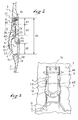
- the rocker 4 is mounted on the collar 3 via a first pivot 6.
- the first pivot 6 is made using a shaft which can be a stud or a metal rod.
- the first pivot 6 is oriented along an axis A1, which is substantially transverse to the shoe.
- the rocker is in the form of an elongated piece, which extends from a first upper end E1 to a lower end E2.
- the rocker 4 further comprises a bearing block 10 located in its lower part. Between the first pivot 6 and the support block 10 is a second pivot 7.
- the bearing block 10 comprises a first bearing surface 18 which is capable of coming into contact with the shell bottom 2 and a second surface. 19 which is likely to come into contact with a stop 24 formed on the collar 3.
- the first pivot 6 is placed near the upper end E1.
- the ratio between the distance d1 separating the first pivot 6 from the first end E1 and the distance d4 separating the first pivot 6 from the second end or the lower end E2 is between 0.15 and 0.35. This ratio is preferably between 0.2 and 0.26. In other words we can write the following mathematical equation: 0 , 2 ⁇ d ⁇ 4 ⁇ d ⁇ 1 ⁇ 0 , 26 ⁇ d ⁇ 4
- the ratio between d1 and d4 is substantially equal to 0.23.
- the smallness of the ratio between d1 and d4, between 0.1 and 0.3 preferably between 0.2 and 0.26, has the consequence that in its movement around the first pivot 6, the upper end E1 will have a much lower amplitude of movement than that of the lower end E2.
- the passage of the locking device in the unlocking state will generate a movement towards the outside of the end E2 while the upper end E1 will be moved with a movement towards the inside.
- the movement inward of the upper end E1 of course requires the development of a corresponding cavity in the collar 3 to allow the end E1 to enter the collar.
- the smallness of the ratio d1 / d4 has the consequence that the cavity to be formed in the collar must be relatively small.
- the bearing block 10 comprises a first bearing surface 18, which merges with the second end E2, and a second bearing surface 19 in the blocking state, the first bearing surface 18 is in position. contact with a sidewalk 11 formed in the shell bottom, while the second bearing surface 19 is in contact with a stop 24 formed in the lower part of the collar 3.
- the bearing block 10 occupies a protruding position relative to the rest of the rocker 4. Thus it can easily come to interpose between the abutment 24 of the collar and the sidewalk 11 of the bottom of the hull.
- the second pivot 7 also made by means of a metal rod or a rivet or by any other known means is oriented along an axis A2.
- the lever 5 is in the form of a jumper extended by a pallet 13 for actuating the latter.
- the two branches of the rider are bearings 25 which are placed on each side of the rocker 4.
- the bearings are pierced with an opening provided for receiving the second pivot 7, and their outer surface is constituted by a cam surface 26 intended to come into contact with a rolling surface 23 formed on the collar 3.
- the locking device also comprises return means 14 provided to bring the lower part of the rocker 4, that is to say the bearing block 10, against the boot.
- these return means 14 are in the form of one or more springs working in compression which is placed at the end E1.
- the cam surface 26 formed on each of the bearings 25 has a final portion 21, which is at a distance C1 from the second pivot 7, and a final portion 22, which is at a distance C2 from the second pivot 7. blocking is in the blocking state, it is the initial portion 21 of the cam surface 26 which is opposite the rolling surface 23, formed on the collar 3.
- the rocker 4 is pivotally mounted relative to the collar 3 around the first pivot 6, while the lever is pivotally mounted relative to the rocker 4 around the second pivot 7. It will be seen later that the rotation of the lever 5 causes the pivoting of the rocker 4 by the effect of the cam surfaces disposed on the bearings.
- the Figures 4 and 5 describe the previous shoe in the unlock state, that is, in the "ON" position.
- the rocker 4 is pivoted around the first pivot 6 so that its lower end E2 is displaced towards the outside of the shoe 1.
- the rotational movement of the rocker 4 must have an amplitude such that the tip of the rocker 28 is no longer facing sidewalk 11.
- the amplitude of this movement corresponds to an angle ⁇ whose value is between 3 ° and 25 °, preferably between 5 ° and 15 °. In the example shown, ⁇ is between 8 ° and 10 °.
- the abutment 24 of the collar and the sidewalk 11 of the shell bottom are free of relative movement relative to each other and they can move closer to each other. There is no more back support. Walking is then facilitated because of the lack of back support, the user can lay flat foot in front of him.
- the rotational movement of the rocker 4 is generated by the action of the user on the lever 5.
- the latter is represented at the figure 5 when the locking device is in the unlocking state.
- the transition from the blocking state to the unlocking state occurs when the user moves the pallet 13 of the lever 5 upwards.
- the rotational movement of the lever 5 around the second pivot 7 is a movement whose amplitude is materialized at the figure 4 a straight line connecting the second pivot 7 and the tip 27 of the lever in both positions.
- the amplitude of this movement corresponds to an angle ⁇ , which is between 90 ° and 160 °, preferably 120 ° and 150 °. In the example shown, ⁇ is substantially equal to 135 °.
Landscapes
- Health & Medical Sciences (AREA)
- General Health & Medical Sciences (AREA)
- Physical Education & Sports Medicine (AREA)
- Footwear And Its Accessory, Manufacturing Method And Apparatuses (AREA)
- Braking Arrangements (AREA)
Claims (10)
- Schuh (1), der entlang einer Längsachse orientiert ist, und eine untere Schale (2) und einen Kragen (3) umfasst, wobei Gelenkmittel zwischen dem Kragen (3) und der unteren Schale (2) vorgesehen sind, so dass sich der Kragen in Bezug auf die untere Schale um eine Drehachse drehen kann, die im wesentlichen senkrecht zur Längsachse ist, weiterhin eine Blockiervorrichtung für die Rotation des Kragens (3) nach hinten in Bezug auf die untere Schale (2) umfasst, wobei die Blockiervorrichtuingen der Rotation nach hinten umfassen:- eine Kippvorrichtung (4), welche drehbar in Bezug auf eines der zwei folgenden Elemente befestigt ist, den Kragen (3) oder die untere Schale (2) um einen ersten Drehzapfen (6), wobei der Zapfen nach einer ersten Achse A1 orientiert ist und die Kippvorrichtung (4) eine gestreckte Form zwischen einem oberen Ende E1 (8) und einem unteren Ende E2 (9) aufweist, und sich der erste Zapfen (6) in der Nähe von einem der zwei Enden E1 oder E2 angeordnet befindet;- ein Auflagefeld (10), welches in der Nähe des anderen der Enden E2 oder E1 angeordnet ist und eine erste Auflageoberfläche (18) umfasst, welche dafür vorgesehen ist, in Kontakt mit dem anderen der folgenden Elemente zu treten, nämlich der unteren Schale (2) oder dem Kragen (3); und- einen Hebel (5), der in Bezug auf die Kippvorrichtung (4) drehbar um einen zweiten Zapfen (7) befestigt ist, wobei der zweite Zapfen (7) nach einer zweiten Achse A2 orientiert ist, die parallel zur ersten Achse A1 ist, und der zweite Zapfen (7) zwischen dem ersten Zapfen (6) und dem Auflagefeld angeordnet ist, wobei der Hebel (5) eine Betätigungspalette (13) und eine Nockenoberfläche umfasst.
- Schuh nach Anspruch 1, dadurch, gekennzeichnet, dass die Kippvorrichtung (4) drehbar auf dein Kragen befestigt ist, und dadurch, dass sich der erste Zapfen (6) in der Nähe des oberen Endes E1 angeordnet befindet, und dadurch, dass das Auflagefeld (10) in der Nähe des unteren Endes E2 angeordnet ist.
- Schuh nach einem der vorigen Anspruche, dadurch gekennzeichnet, dass die Blookiervorrichtung dazu vorgesehen ist, sich in einem Blockierzustand zu befinden, in welchem sie die Rotation nach hinten der Rotationsbewegung des Kragens (3) in Bezug auf die untere Schale (2) verhindert, oder in einen Nichtblockierzustand, in welchem diese Drehung nicht verhindert ist.
- Schuh nach einem der Ansprüche 2 bis 3, dadurch gekennzeichnet, dass die erste Auflageoberfläche (18) des Auflagefeldes (10) dem anderen der Enden E2 oder E1 entspricht, und dadurch, dass die Beziehung zwischen der Entfernung d1, welche den ersten Zapfen (6) von dem ersten Ende E1 trennt und der Entfernung d4, welche den ersten Zapfen (6) von dem zweiten Ende E2 trennt, zwischen 0,15 und 0,35 beträgt:

- Schuh nach einem der Ansprüche 1 bis 4, dadurch gekennzeichnet, dass die Beziehung zwischen der Entfernung d2, die den ersten Zapfen (6) vom zweiten Zapfen (7) trennt, und die Entfernung d4, die den ersten Zapfen (6) von dem unteren Ende E2 trennt, zwischen 0,2 und 0,5 beträgt;

- Schuh nach einem der vorigen Ansprüche, dadurch, gekennzeichnet, dass die Kippvorrichtung (4) sich zwischen einer Blockierposition, in welcher während der Drehbewegung des Kragens (3) nach hinten die erste Auflageoberfläche (18) in Kontakt mit einem Weg (11) tritt, der auf der unteren Schale (2) angeordnet ist, und einer Nichtblockierposition, in welcher die Kippvorrichtung (4) die Drehung des Kragens (3) nach hinten entriegelt, drehen kann, und dadurch, dass die Amplitude der Drehbewegung der Kippvorrichtung (4) einem Winkel β entspricht, dessen Wert zwischen 3° < β < 25° liegt.
- Schuh nach den vorigen Anspruch, dadurch gekennzeichnet, dass der Winkel β zwischen 3° < β < 15° liegt.
- Schuh nach einem der vorigen Ansprüche, dadurch gekennzeichnet, dass die Blockiervorrichtung darüber hinaus Rückstellmittel (14) unfasst, die zumindest eine Feder umfassen und die die Blockiervorrichtung in den Blockierzustand zurückbringen.
- Schuh nach einem der vorigen Ansprüche, dadurch gekennzeichnet, dass der Hebel (5) den Durchgang vom Blockierzustand zu einem entriegelten Zustand der Blockiervorrichtung ermöglicht, und dadurch, dass die Nockenoberfläche einen Initialabschnitt (21) umfasst, welcher mit einer Entfernung C1 von dem zweiten Zapfen (7) angeordnet ist, und einen Endabschnitt (22), der mit einer Entfernung C2 von dem zweiten Zapfen (7) angeordnet ist, wenn die Palette (13) des Hebels (5) durch den Nutzer mit einer Amplitude in Drehung versetzt wird, die einem Winkel α entspricht, dessen Wert zwischen 120° und 160° liegt:

- Schuh nach einem der vorigen Ansprüche, dadurch gekennzeichnet, dass das Auflagefeld eine zweite Auflagenoberfläche (19) umfasst, die, während die Blockiervorrichtung in dem Blockierzustand ist, für des Inkontakttreten mit einem Anschlag (24) verantwortlich ist, der auf dein Kragen (3) angebracht ist.
Applications Claiming Priority (1)
| Application Number | Priority Date | Filing Date | Title |
|---|---|---|---|
| FR0708747A FR2924904B1 (fr) | 2007-12-14 | 2007-12-14 | Chaussure de sport avec dispositif de blocage |
Publications (2)
| Publication Number | Publication Date |
|---|---|
| EP2070433A1 EP2070433A1 (de) | 2009-06-17 |
| EP2070433B1 true EP2070433B1 (de) | 2010-07-21 |
Family
ID=39722596
Family Applications (1)
| Application Number | Title | Priority Date | Filing Date |
|---|---|---|---|
| EP08021317A Active EP2070433B1 (de) | 2007-12-14 | 2008-12-09 | Sportschuh mit Blockiervorrichtung |
Country Status (5)
| Country | Link |
|---|---|
| US (1) | US8132343B2 (de) |
| EP (1) | EP2070433B1 (de) |
| AT (1) | ATE474467T1 (de) |
| DE (1) | DE602008001862D1 (de) |
| FR (1) | FR2924904B1 (de) |
Families Citing this family (12)
| Publication number | Priority date | Publication date | Assignee | Title |
|---|---|---|---|---|
| FR2924904B1 (fr) * | 2007-12-14 | 2010-01-01 | Salomon Sa | Chaussure de sport avec dispositif de blocage |
| EP2486817B1 (de) | 2011-02-03 | 2016-11-16 | Rossignol Lange S.R.L. | Sportschuh mit angelenktem Schaft für eine Laufstellung |
| ITPD20110331A1 (it) * | 2011-10-20 | 2013-04-21 | Garmont S R L | Scarpone da sci con meccanismo migliorato della selezione sciata-camminata |
| EP2612568A1 (de) * | 2012-01-04 | 2013-07-10 | K-2 Corporation | Ski-/Lauf-Mechanismus |
| ITTV20120053A1 (it) * | 2012-04-04 | 2013-10-05 | Scarpa Calzaturificio Spa | Scarpone da sci |
| ITVE20130028A1 (it) * | 2013-06-11 | 2014-12-12 | Ober Alp Spa | Scarpone da sci, in particolare da sci alpinismo.- |
| USD985243S1 (en) | 2013-11-12 | 2023-05-09 | Riomar Ip, Llc | Shoe device |
| FR3015190B1 (fr) | 2013-12-20 | 2016-07-01 | Salomon Sas | Chaussure de sport |
| FR3016775B1 (fr) | 2014-01-24 | 2020-11-20 | Salomon Sas | Chaussure de sport |
| ES2906567T3 (es) * | 2015-05-06 | 2022-04-19 | Ober Alp Spa | Bota de esquí provista de un mecanismo de selección de esquí-marcha mejorado |
| US11278079B2 (en) * | 2018-01-16 | 2022-03-22 | Phantom Snow Industries Llc | Adjustable and dual-suspension boot levers |
| US11684124B2 (en) * | 2020-09-24 | 2023-06-27 | Charles H. Brown, III | Accessory wearable around a boot shaft |
Family Cites Families (20)
| Publication number | Priority date | Publication date | Assignee | Title |
|---|---|---|---|---|
| FR2454767A2 (fr) * | 1978-06-16 | 1980-11-21 | Salomon & Fils F | Chaussure de ski |
| CH644501A5 (fr) * | 1982-02-18 | 1984-08-15 | Lange Int Sa | Chaussure de ski. |
| DE3502522A1 (de) * | 1984-02-10 | 1985-08-14 | SALOMON S.A., Annecy, Haute-Savoie | Betaetigungshebel zum verschliessen und verriegeln eines skistiefels mit einstieg von hinten |
| CH668888A5 (fr) * | 1986-04-18 | 1989-02-15 | Lange Int Sa | Chaussure de ski. |
| CH669718A5 (de) * | 1986-06-06 | 1989-04-14 | Lange Int Sa | |
| US4839973A (en) * | 1987-04-09 | 1989-06-20 | Lange International S.A. | Ski boot |
| CH682879A5 (fr) * | 1990-04-24 | 1993-12-15 | Lange Int Sa | Chaussure de ski. |
| FR2677229B1 (fr) * | 1991-06-10 | 1993-10-15 | Salomon Sa | Perfectionnement pour chaussure de ski. |
| FR2694681B1 (fr) * | 1992-08-11 | 1994-11-04 | Salomon Sa | Chaussure de ski alpin. |
| FR2702341B1 (fr) * | 1993-03-12 | 1995-06-09 | Rossignol Sa | Chaussure de ski a coque et collier. |
| CH688635A5 (fr) * | 1993-04-02 | 1997-12-31 | Lange Int Sa | Chaussure de ski. |
| FR2714801B1 (fr) * | 1994-01-12 | 1996-03-01 | Salomon Sa | Chaussure de ski à inclinaison de tige variable. |
| ITVE940003A1 (it) * | 1994-02-04 | 1995-08-04 | Htm Sport Spa | Scarpone da sci provvisto di dispositivo di bloccaggio del gambaletto rispetto allo scafo |
| FR2722066B1 (fr) * | 1994-07-07 | 1996-08-30 | Salomon Sa | Reglage de flexibilite de chaussure de ski |
| FR2752684B1 (fr) * | 1996-09-04 | 1998-10-30 | Salomon Sa | Chaussure de sport munie d'un dispositif d'immobilisation en pivotement de la tige |
| IT1297290B1 (it) * | 1997-11-05 | 1999-09-01 | Tecnica Spa | Perfezionamento relativo ai dispositivi di bloccaggio per calzature sportive in particolare per scarponi da sci. |
| US6263593B1 (en) * | 1998-06-19 | 2001-07-24 | Lange International S.A. | Retention and release mechanism for a ski boot and ski boot incorporating the same |
| US6643955B2 (en) * | 1998-06-19 | 2003-11-11 | Lange International S.A. | Retention and release mechanism for a ski boot and ski boot incorporating the same |
| ATE416642T1 (de) * | 2006-10-11 | 2008-12-15 | Lisa Lange Internat Sarl | Sport shoe with articulated cuff for a walking position |
| FR2924904B1 (fr) * | 2007-12-14 | 2010-01-01 | Salomon Sa | Chaussure de sport avec dispositif de blocage |
-
2007
- 2007-12-14 FR FR0708747A patent/FR2924904B1/fr not_active Expired - Fee Related
-
2008
- 2008-12-09 EP EP08021317A patent/EP2070433B1/de active Active
- 2008-12-09 DE DE602008001862T patent/DE602008001862D1/de active Active
- 2008-12-09 AT AT08021317T patent/ATE474467T1/de active
- 2008-12-12 US US12/333,760 patent/US8132343B2/en active Active
Also Published As
| Publication number | Publication date |
|---|---|
| ATE474467T1 (de) | 2010-08-15 |
| US8132343B2 (en) | 2012-03-13 |
| FR2924904A1 (fr) | 2009-06-19 |
| FR2924904B1 (fr) | 2010-01-01 |
| EP2070433A1 (de) | 2009-06-17 |
| DE602008001862D1 (de) | 2010-09-02 |
| US20090178304A1 (en) | 2009-07-16 |
Similar Documents
| Publication | Publication Date | Title |
|---|---|---|
| EP2070433A1 (de) | Sportschuh mit Blockiervorrichtung | |
| EP0424210B1 (de) | Schuhbefestigungsvorrichtung an einem Fahrradpedal oder dergleichen, Fahrradpedal, Riegel und Schuhsohle für eine derartige Vorrichtung | |
| EP3260178B1 (de) | Fersenhalter zur befestigung eines schuhes auf einem snowboard | |
| CA1131668A (fr) | Dispositif de maintien d'une extremite d'une chaussure sur un ski, notamment fixation pour ski de fond ou de randonnee | |
| EP2687275B1 (de) | Vordere Haltevorrichtungen eines Gleitbrettes | |
| CA1331388C (fr) | Fixation de ski de fond de type charniere | |
| EP1213980A1 (de) | Vorrichtung zur positionsverriegelung eines bezüglich eines ortsfesten elements beweglichen teils | |
| EP2486817B1 (de) | Sportschuh mit angelenktem Schaft für eine Laufstellung | |
| FR2807384A1 (fr) | Dispositif de fixation automatique et pedale de cycliste pourvue d'un tel dispositif | |
| EP3437703B1 (de) | Bremsvorrichtung für tourenski | |
| EP3747751A1 (de) | Automatisches pedal für fahrrad | |
| EP3235779A1 (de) | Sicherheitssteigbügel für reitsport | |
| EP1104251A1 (de) | Langlaufskischuh | |
| FR2467612A1 (fr) | Frein de ski | |
| FR2578168A1 (fr) | Fixation et chaussure de ski, notamment pour ski de fond. | |
| EP3184156B1 (de) | Skibindung | |
| FR2642656A1 (fr) | Fixation de securite pour ski destinee a maintenir l'avant d'une chaussure montee sur le ski | |
| EP3564108B1 (de) | Fahrradpedal mit schuhplatteneingriffselement | |
| EP4397203B1 (de) | Verriegelungsvorrichtung für einen sportschuh | |
| FR2543445A1 (fr) | Fixation de securite pour ski | |
| EP3335772B1 (de) | Einheit stock / bekleidungsartikel | |
| CH656542A5 (fr) | Fixation de securite pour ski. | |
| FR2590803A1 (fr) | Fixation pour ski de fond | |
| EP4397202A1 (de) | Verriegelungsvorrichtung für einen sportschuh | |
| FR3144908A1 (fr) | Dispositif de verrouillage pour une chaussure de sport |
Legal Events
| Date | Code | Title | Description |
|---|---|---|---|
| PUAI | Public reference made under article 153(3) epc to a published international application that has entered the european phase |
Free format text: ORIGINAL CODE: 0009012 |
|
| AK | Designated contracting states |
Kind code of ref document: A1 Designated state(s): AT BE BG CH CY CZ DE DK EE ES FI FR GB GR HR HU IE IS IT LI LT LU LV MC MT NL NO PL PT RO SE SI SK TR |
|
| AX | Request for extension of the european patent |
Extension state: AL BA MK RS |
|
| 17P | Request for examination filed |
Effective date: 20091120 |
|
| GRAP | Despatch of communication of intention to grant a patent |
Free format text: ORIGINAL CODE: EPIDOSNIGR1 |
|
| AKX | Designation fees paid |
Designated state(s): AT BE BG CH CY CZ DE DK EE ES FI FR GB GR HR HU IE IS IT LI LT LU LV MC MT NL NO PL PT RO SE SI SK TR |
|
| GRAS | Grant fee paid |
Free format text: ORIGINAL CODE: EPIDOSNIGR3 |
|
| GRAA | (expected) grant |
Free format text: ORIGINAL CODE: 0009210 |
|
| AK | Designated contracting states |
Kind code of ref document: B1 Designated state(s): AT BE BG CH CY CZ DE DK EE ES FI FR GB GR HR HU IE IS IT LI LT LU LV MC MT NL NO PL PT RO SE SI SK TR |
|
| REG | Reference to a national code |
Ref country code: GB Ref legal event code: FG4D Free format text: NOT ENGLISH |
|
| REG | Reference to a national code |
Ref country code: CH Ref legal event code: EP |
|
| REG | Reference to a national code |
Ref country code: IE Ref legal event code: FG4D |
|
| REF | Corresponds to: |
Ref document number: 602008001862 Country of ref document: DE Date of ref document: 20100902 Kind code of ref document: P |
|
| REG | Reference to a national code |
Ref country code: NL Ref legal event code: VDEP Effective date: 20100721 |
|
| LTIE | Lt: invalidation of european patent or patent extension |
Effective date: 20100721 |
|
| PG25 | Lapsed in a contracting state [announced via postgrant information from national office to epo] |
Ref country code: NL Free format text: LAPSE BECAUSE OF FAILURE TO SUBMIT A TRANSLATION OF THE DESCRIPTION OR TO PAY THE FEE WITHIN THE PRESCRIBED TIME-LIMIT Effective date: 20100721 Ref country code: LT Free format text: LAPSE BECAUSE OF FAILURE TO SUBMIT A TRANSLATION OF THE DESCRIPTION OR TO PAY THE FEE WITHIN THE PRESCRIBED TIME-LIMIT Effective date: 20100721 Ref country code: NO Free format text: LAPSE BECAUSE OF FAILURE TO SUBMIT A TRANSLATION OF THE DESCRIPTION OR TO PAY THE FEE WITHIN THE PRESCRIBED TIME-LIMIT Effective date: 20101021 Ref country code: FI Free format text: LAPSE BECAUSE OF FAILURE TO SUBMIT A TRANSLATION OF THE DESCRIPTION OR TO PAY THE FEE WITHIN THE PRESCRIBED TIME-LIMIT Effective date: 20100721 |
|
| REG | Reference to a national code |
Ref country code: IE Ref legal event code: FD4D |
|
| PG25 | Lapsed in a contracting state [announced via postgrant information from national office to epo] |
Ref country code: HR Free format text: LAPSE BECAUSE OF FAILURE TO SUBMIT A TRANSLATION OF THE DESCRIPTION OR TO PAY THE FEE WITHIN THE PRESCRIBED TIME-LIMIT Effective date: 20100721 Ref country code: BG Free format text: LAPSE BECAUSE OF FAILURE TO SUBMIT A TRANSLATION OF THE DESCRIPTION OR TO PAY THE FEE WITHIN THE PRESCRIBED TIME-LIMIT Effective date: 20101021 Ref country code: SI Free format text: LAPSE BECAUSE OF FAILURE TO SUBMIT A TRANSLATION OF THE DESCRIPTION OR TO PAY THE FEE WITHIN THE PRESCRIBED TIME-LIMIT Effective date: 20100721 Ref country code: PL Free format text: LAPSE BECAUSE OF FAILURE TO SUBMIT A TRANSLATION OF THE DESCRIPTION OR TO PAY THE FEE WITHIN THE PRESCRIBED TIME-LIMIT Effective date: 20100721 Ref country code: IS Free format text: LAPSE BECAUSE OF FAILURE TO SUBMIT A TRANSLATION OF THE DESCRIPTION OR TO PAY THE FEE WITHIN THE PRESCRIBED TIME-LIMIT Effective date: 20101121 Ref country code: CY Free format text: LAPSE BECAUSE OF FAILURE TO SUBMIT A TRANSLATION OF THE DESCRIPTION OR TO PAY THE FEE WITHIN THE PRESCRIBED TIME-LIMIT Effective date: 20100721 |
|
| PG25 | Lapsed in a contracting state [announced via postgrant information from national office to epo] |
Ref country code: LV Free format text: LAPSE BECAUSE OF FAILURE TO SUBMIT A TRANSLATION OF THE DESCRIPTION OR TO PAY THE FEE WITHIN THE PRESCRIBED TIME-LIMIT Effective date: 20100721 Ref country code: GR Free format text: LAPSE BECAUSE OF FAILURE TO SUBMIT A TRANSLATION OF THE DESCRIPTION OR TO PAY THE FEE WITHIN THE PRESCRIBED TIME-LIMIT Effective date: 20101022 Ref country code: SE Free format text: LAPSE BECAUSE OF FAILURE TO SUBMIT A TRANSLATION OF THE DESCRIPTION OR TO PAY THE FEE WITHIN THE PRESCRIBED TIME-LIMIT Effective date: 20100721 |
|
| PG25 | Lapsed in a contracting state [announced via postgrant information from national office to epo] |
Ref country code: IE Free format text: LAPSE BECAUSE OF FAILURE TO SUBMIT A TRANSLATION OF THE DESCRIPTION OR TO PAY THE FEE WITHIN THE PRESCRIBED TIME-LIMIT Effective date: 20100721 Ref country code: DK Free format text: LAPSE BECAUSE OF FAILURE TO SUBMIT A TRANSLATION OF THE DESCRIPTION OR TO PAY THE FEE WITHIN THE PRESCRIBED TIME-LIMIT Effective date: 20100721 |
|
| PLBE | No opposition filed within time limit |
Free format text: ORIGINAL CODE: 0009261 |
|
| STAA | Information on the status of an ep patent application or granted ep patent |
Free format text: STATUS: NO OPPOSITION FILED WITHIN TIME LIMIT |
|
| PG25 | Lapsed in a contracting state [announced via postgrant information from national office to epo] |
Ref country code: SK Free format text: LAPSE BECAUSE OF FAILURE TO SUBMIT A TRANSLATION OF THE DESCRIPTION OR TO PAY THE FEE WITHIN THE PRESCRIBED TIME-LIMIT Effective date: 20100721 Ref country code: RO Free format text: LAPSE BECAUSE OF FAILURE TO SUBMIT A TRANSLATION OF THE DESCRIPTION OR TO PAY THE FEE WITHIN THE PRESCRIBED TIME-LIMIT Effective date: 20100721 Ref country code: EE Free format text: LAPSE BECAUSE OF FAILURE TO SUBMIT A TRANSLATION OF THE DESCRIPTION OR TO PAY THE FEE WITHIN THE PRESCRIBED TIME-LIMIT Effective date: 20100721 Ref country code: CZ Free format text: LAPSE BECAUSE OF FAILURE TO SUBMIT A TRANSLATION OF THE DESCRIPTION OR TO PAY THE FEE WITHIN THE PRESCRIBED TIME-LIMIT Effective date: 20100721 |
|
| 26N | No opposition filed |
Effective date: 20110426 |
|
| BERE | Be: lapsed |
Owner name: SALOMON S.A.S. Effective date: 20101231 |
|
| PG25 | Lapsed in a contracting state [announced via postgrant information from national office to epo] |
Ref country code: ES Free format text: LAPSE BECAUSE OF FAILURE TO SUBMIT A TRANSLATION OF THE DESCRIPTION OR TO PAY THE FEE WITHIN THE PRESCRIBED TIME-LIMIT Effective date: 20101101 |
|
| PG25 | Lapsed in a contracting state [announced via postgrant information from national office to epo] |
Ref country code: MC Free format text: LAPSE BECAUSE OF NON-PAYMENT OF DUE FEES Effective date: 20101231 |
|
| REG | Reference to a national code |
Ref country code: DE Ref legal event code: R097 Ref document number: 602008001862 Country of ref document: DE Effective date: 20110426 |
|
| PG25 | Lapsed in a contracting state [announced via postgrant information from national office to epo] |
Ref country code: BE Free format text: LAPSE BECAUSE OF NON-PAYMENT OF DUE FEES Effective date: 20101231 |
|
| PG25 | Lapsed in a contracting state [announced via postgrant information from national office to epo] |
Ref country code: MT Free format text: LAPSE BECAUSE OF FAILURE TO SUBMIT A TRANSLATION OF THE DESCRIPTION OR TO PAY THE FEE WITHIN THE PRESCRIBED TIME-LIMIT Effective date: 20100721 |
|
| PG25 | Lapsed in a contracting state [announced via postgrant information from national office to epo] |
Ref country code: LU Free format text: LAPSE BECAUSE OF NON-PAYMENT OF DUE FEES Effective date: 20101209 Ref country code: HU Free format text: LAPSE BECAUSE OF FAILURE TO SUBMIT A TRANSLATION OF THE DESCRIPTION OR TO PAY THE FEE WITHIN THE PRESCRIBED TIME-LIMIT Effective date: 20110122 |
|
| PG25 | Lapsed in a contracting state [announced via postgrant information from national office to epo] |
Ref country code: TR Free format text: LAPSE BECAUSE OF FAILURE TO SUBMIT A TRANSLATION OF THE DESCRIPTION OR TO PAY THE FEE WITHIN THE PRESCRIBED TIME-LIMIT Effective date: 20100721 |
|
| PG25 | Lapsed in a contracting state [announced via postgrant information from national office to epo] |
Ref country code: PT Free format text: LAPSE BECAUSE OF NON-PAYMENT OF DUE FEES Effective date: 20100721 |
|
| GBPC | Gb: european patent ceased through non-payment of renewal fee |
Effective date: 20121209 |
|
| PG25 | Lapsed in a contracting state [announced via postgrant information from national office to epo] |
Ref country code: GB Free format text: LAPSE BECAUSE OF NON-PAYMENT OF DUE FEES Effective date: 20121209 |
|
| PGFP | Annual fee paid to national office [announced via postgrant information from national office to epo] |
Ref country code: CH Payment date: 20141212 Year of fee payment: 7 |
|
| PGFP | Annual fee paid to national office [announced via postgrant information from national office to epo] |
Ref country code: AT Payment date: 20141125 Year of fee payment: 7 |
|
| PGFP | Annual fee paid to national office [announced via postgrant information from national office to epo] |
Ref country code: IT Payment date: 20141128 Year of fee payment: 7 |
|
| REG | Reference to a national code |
Ref country code: FR Ref legal event code: PLFP Year of fee payment: 8 |
|
| REG | Reference to a national code |
Ref country code: CH Ref legal event code: PL |
|
| REG | Reference to a national code |
Ref country code: AT Ref legal event code: MM01 Ref document number: 474467 Country of ref document: AT Kind code of ref document: T Effective date: 20151209 |
|
| PG25 | Lapsed in a contracting state [announced via postgrant information from national office to epo] |
Ref country code: LI Free format text: LAPSE BECAUSE OF NON-PAYMENT OF DUE FEES Effective date: 20151231 Ref country code: CH Free format text: LAPSE BECAUSE OF NON-PAYMENT OF DUE FEES Effective date: 20151231 |
|
| REG | Reference to a national code |
Ref country code: FR Ref legal event code: PLFP Year of fee payment: 9 |
|
| PG25 | Lapsed in a contracting state [announced via postgrant information from national office to epo] |
Ref country code: AT Free format text: LAPSE BECAUSE OF NON-PAYMENT OF DUE FEES Effective date: 20151209 |
|
| PG25 | Lapsed in a contracting state [announced via postgrant information from national office to epo] |
Ref country code: IT Free format text: LAPSE BECAUSE OF NON-PAYMENT OF DUE FEES Effective date: 20151209 |
|
| REG | Reference to a national code |
Ref country code: FR Ref legal event code: PLFP Year of fee payment: 10 |
|
| PGFP | Annual fee paid to national office [announced via postgrant information from national office to epo] |
Ref country code: DE Payment date: 20241029 Year of fee payment: 17 |
|
| PGFP | Annual fee paid to national office [announced via postgrant information from national office to epo] |
Ref country code: FR Payment date: 20251119 Year of fee payment: 18 |