EP3335772B1 - Einheit stock / bekleidungsartikel - Google Patents
Einheit stock / bekleidungsartikel Download PDFInfo
- Publication number
- EP3335772B1 EP3335772B1 EP17206423.0A EP17206423A EP3335772B1 EP 3335772 B1 EP3335772 B1 EP 3335772B1 EP 17206423 A EP17206423 A EP 17206423A EP 3335772 B1 EP3335772 B1 EP 3335772B1
- Authority
- EP
- European Patent Office
- Prior art keywords
- rocker
- grip
- pole
- housing
- handle
- Prior art date
- Legal status (The legal status is an assumption and is not a legal conclusion. Google has not performed a legal analysis and makes no representation as to the accuracy of the status listed.)
- Active
Links
Images




Classifications
-
- A—HUMAN NECESSITIES
- A63—SPORTS; GAMES; AMUSEMENTS
- A63C—SKATES; SKIS; ROLLER SKATES; DESIGN OR LAYOUT OF COURTS, RINKS OR THE LIKE
- A63C11/00—Accessories for skiing or snowboarding
- A63C11/22—Ski-sticks
- A63C11/227—Details; Structure
-
- A—HUMAN NECESSITIES
- A63—SPORTS; GAMES; AMUSEMENTS
- A63C—SKATES; SKIS; ROLLER SKATES; DESIGN OR LAYOUT OF COURTS, RINKS OR THE LIKE
- A63C11/00—Accessories for skiing or snowboarding
- A63C11/22—Ski-sticks
- A63C11/222—Ski-stick handles or hand-straps
- A63C11/2224—Connection systems for hand-straps
Definitions
- the invention relates to sets consisting of a stick and a clothing item. Such sets can in particular be used during the practice of downhill skiing, cross-country skiing, ski touring, hiking or racing in the mountains or Nordic walking (called “Nordic walking” in English).
- the article of clothing associated with the pole is generally a strap wrapped around the skier's hand.
- the wrist strap can take the form of a glove or a strap forming a closed loop, or any other intermediate form. By being connected to the handle, the strap prevents the skier from losing the pole when he releases the handle.
- the wrist strap also makes it possible to improve the transmission of the pushing forces of the skier on the pole, which proves to be particularly advantageous for the practice of winter sports and summer activities mentioned above.
- the wrist strap also allows these support forces to be transmitted for a longer period, in particular because it can be carried out without clenching one's fingers around the handle.
- Some designs provide trigger mechanisms.
- the article of clothing can thus selectively be attached to or detached from the handle.
- the document US 8,079,617 B2 describes a stick handle comprising a body and a device for snapping on a clothing item intended to at least partially cover the hand of a user.
- the latching device includes a tab rotatably mounted on the body.
- the article of clothing is provided with a fastening element intended to be introduced into a recess in the tab of the latching device in order to engage a fixed retaining lug constituting a part of the external periphery of the handle.
- the latch of the latching device is configured together with the body of the handle to switch between a locking position of the fastening element around the lug and an unlocking position of the fastener.
- the transition from the locking position to the unlocking position can be linked to the application of a force on the tab via the fastening element, this force being oriented towards the top of the stick.
- the transition from the unlocking position to the locking position can be linked to the application of a force on the tab via the fastening element, this force being directed towards the bottom of the stick, or linked to the support of the user on the upper part of the tab.
- the tab is configured to be held in one or the other of the two locking and unlocking positions by the cooperation of a finger secured to the tab of the latching device respectively with one or the other of two housings in the body of the handle.
- a return device can be arranged jointly with the tab and the finger to allow the finger to withdraw from the housing in which it is engaged and come to engage in the other housing following the tilting of the tab.
- a problem with this latching device comes in particular from the fact that it does not include a return device bringing the tab in its stable locking position. Consequently, the locking of the fastening element is not automatic after its introduction into a recess in the tab. The user must necessarily act on the tab, in a particular direction, to obtain the locking. In addition, it cannot be certain of the effective locking of the fastening element if it does not act correctly on the tab, for example, by exerting a bias force via the wrist strap. In addition, the space constraints linked to this construction induce locking members and a return device of small dimensions. Consequently, there is a risk of malfunction of the locking members linked to wear, to environmental conditions in particular as a function of the temperature of use and the clogging of the handle.
- the document EP 2 883 583 A1 describes a stick / article of clothing in which the body of the handle comprises a housing intended to receive the fastening element of the article of clothing.
- a retainer is movably mounted in the body of the handle between a retainer position of the fastener and a release position of the retainer.
- a latch is further mounted movable in the body between a locking position in which the latch keeps the retaining element in its retaining position and an unlocking position in which the latch no longer keeps the retaining element in its position of restraint.
- the handle also comprises a return means urging the lock towards its locking position to reduce the risk of involuntary detachment from the item of clothing. To release the item of clothing, the lock must be actuated by acting against the force generated by the return means.
- One problem with this device is that the unlocking of the item of clothing is not automatic, in particular in the event of the stick being blocked.
- the document US 8,579,329 B2 describes a stick handle comprising a lock mounted in translation in a rocker rotatably mounted on the body of the handle.
- the rocker pivots between a retaining position and a release position.
- the rocker is arranged jointly with a first return means tending to keep it in its retaining position.
- the lock is movable in translation between a locking position and an unlocking position of the fastening element of a clothing item.
- the lock is arranged jointly with a second return means tending to keep it in its locked position.
- the lock When the rocker is in its release position, the lock is still in its locked position, but the rotation of the rocker means that the lock is no longer pressing against the fixed retaining lug.
- the fastening element is threaded onto the fixed retaining lug. During this user-generated movement, the fastener pushes the latch to its unlocked position. As soon as the fastening element is sufficiently depressed on the retaining lug, the latch returns to its position of locking by pressing against the retaining lug.
- the user actuates an unlocking mechanism making it possible to move the lock to its unlocking position.
- the lock can no longer secure the article of clothing with the handle or manually detach the article of clothing from the handle.
- the rocker is locked in the retaining position
- the user can no longer trigger the mechanism via the rocker.
- wear on the lock can disturb the operation of the release mechanism. Indeed, the lock can then be actuated by the fixing element by a vertical upward action which would cause untimely triggering of the mechanism for forces below the triggering threshold.
- the fastening element moves independently of any element of the handle, which presents a risk of additional wear by friction against an element of the handle, in particular with the latch which exerts a significant force during the locking of the clothing item.
- the object of the invention is to provide an alternative stick / clothing item.
- One goal is in particular to offer a stick and clothing item that is reliable and robust.
- Another goal is to offer a stick / clothing item whose ergonomics are simple.
- An object of the invention is to propose a stick / clothing item assembly which makes it possible to overcome one or more of the drawbacks of known assemblies.
- the article of clothing is provided with a fastening element with the handle.
- the retaining element is able to cooperate with the fixing element in order to secure the fixing element with the retaining element in at least one direction.
- the rocker is intended to cooperate with the fixing element.
- the scale comprising a housing configured to house at least part of the fastening element of the item of clothing,
- the assembly is such that the handle further comprises a return device configured to exert on the rocker a return force tending to bring it from its unlocking position to its locking position.
- the technical effect obtained is that the lever automatically returns to its stable locking position, in particular after being moved to its unstable unlocking position.
- the locking of the item of clothing can therefore be automatic.
- This characteristic contributes to facilitating at least this assembly. In particular, this operation can be carried out with one hand.
- the user may not have to exert any force on the article of clothing to switch the rocker from its unlocking position to its locking position.
- this mechanism allows better control of the triggering effort allowing the article of clothing to be released from the handle following an effort exerted on the article of clothing.
- the fact that the fixing element is guided by the movement of the rocker, this brings more reliability.
- the lever can be able to switch from its locked position to its unlocked position under the action of a force opposite to the restoring force exerted by the return device on the lever.
- the return device is configured so that the return force it exerts on the scale is directed towards a lower part of the stick.
- the invention has any of the following features which can be used separately or in combination.
- the handle comprises a mechanism for adjusting the return force exerted by the return device.
- the restoring force exerted by the restoring mechanism on the scale can be the only one to counterbalance in order to separate the article of clothing and the handle of the stick between them, the adjustment device makes it possible to finely and simply adjust the tension which is likely to undergo the hand, and the arm, of the user before separation, and this relatively independently of the conditions in particular of temperature in which the stick is used.
- the housing intended to receive a part of the fixing element can be formed in the rocker so that the fixing element is inserted therein in a direction substantially transverse to a longitudinal axis of the handle, preferably by forming an angle between - 45 ° and + 45 ° relative to a plane transverse to the longitudinal axis of the handle. It is therefore excluded that the fastening element is inserted from the top of the handle, and in particular by pulling on the strap so that the rocker moves from its unlocking position to its locking position.
- This construction allows a more intuitive assembly between the article of clothing and the handle, in the direction of the natural grip of the handle. There is no need to thread an eyelet on a retaining lug associated with the handle, this operation can be delicate.
- This characteristic contributes to facilitating at least one of the joining and detaching of the article of clothing and the handle of the stick between them, so that at least one of these operations can be carried out even more easily with one hand.
- this allows the fastening element to be joined to the handle without requiring user action on the item of clothing. This joining is obtained without effort, which is more practical and comfortable.
- the handle may further comprise an elastic member configured jointly with the body and the retaining element to successively stabilize the retaining element in its retaining position and in its release position.
- the scale comprises a first through bore and a second bore, whether through or not, formed respectively in first and second walls of the housing of the scale.
- the retaining element is configured to be able to engage in the housing via the first bore and into the second bore when the rocker is in its locked position.
- the technical effect obtained is that the retaining element is stressed in shear rather than in bending when an effort is exerted on the article of clothing down the handle of the stick, or even in a direction substantially transverse to an axis.
- longitudinal of the handle preferably by forming an angle between - 45 ° and + 45 ° relative to a plane transverse to the longitudinal axis of the handle.
- the assembly is thus mechanically more robust.
- the risk of the retainer breaking is greatly reduced and the life of the mechanism is increased.
- the rocker housing and the retaining element are then of simple relative design, thus increasing the robustness and the ease of use of the assembly.
- the retaining element and the rocker are rotatably mounted on the body of the handle around the same axis of rotation.
- the cooperation of the retaining element and the rocker with the body of the handle is then of relatively simple and economical design, thus increasing the robustness and the ease of use of the assembly.
- the fastening element comprises a plastic or metallic eyelet defining a bore.
- the return device comprises a spring and a tie rod, the tie rod connecting a first end of the spring to the rocker, the second end of the spring being in abutment against the body.
- the housing of the rocker is delimited by a first lower wall on which is formed a first bore and by a second upper wall.
- a second bore is formed in the second upper wall.
- the retaining element is configured to be disposed in the housing of the rocker via the first bore, when the retaining member is in its retaining position and when the rocker is in its locking position.
- a stick equipped with a handle for a stick / clothing item assembly as introduced above.
- a handle for a stick according to the second aspect of the invention.
- the term “fork” means a frame forming a “U”, each branch of which supports one end of a shaft in order to produce a pivot connection (connection to a degree of freedom) with another part pivotally mounted around the tree.
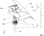
- the present invention relates to a set 1 stick / clothing item comprising a stick 11 provided with a handle 2 and a clothing item 12 provided with a fastening element 123 to the handle 2.
- the article of clothing 12 is a wrist strap.
- the wrist strap 12 comprises an envelope 121 surrounding the wrist of a user and covering at least in part the palm and the back of the user's hand.
- a tongue 122 extends from the envelope 121 of the wrist strap 12 at the junction between the index finger and the thumb.
- the tongue 122 has a free end supporting the fixing element 123 of the strap 12 to the handle 2 of the stick 11.
- the fixing element 123 forms a square or rectangular plate, as illustrated in the figure 9 . It comprises an eyelet 1231 which delimits a bore 1232 passing through the fastening element 123.
- the eyelet 1231 can be made of plastic material chosen to resist the forces to which the internal periphery of the bore 1232 would be subjected.
- the eyelet 1231 envelops the free end of the tongue 122 and is configured to reduce the risk of fraying of the tongue 122 at the bore 1232, in particular when the tongue 122 is made of textile.
- the eyelet can be molded onto the end of the tongue 122.
- the eyelet 1231 is produced by a folded metal blade so as to cover the end of the tongue 122, on each side.
- the fixing element 123 may therefore be an arrangement of the free end of the tongue 122, a part covering the free end of the tongue 122 or a part extending the free end of the tongue 122.
- the stick 11 comprises a tube 111 and a handle 2 fixed to the upper end of the tube 111.
- the tube 111 and the handle 2 share the same longitudinal axis Z2, that of the stick 11.
- the handle 2 comprises a body 20, an actuator 21 and a rocker 22.
- the actuator carries a retaining element 210.
- the body 20 has an elongated shape along the longitudinal axis Z2. It includes an upper part 20a and a lower part 20b.
- the lower part 20b here has a bore (referenced 202 on the figure 2 ) in which the tube 111 is fitted.
- the upper part 20a of the body 20 locally forms a yoke supporting a shaft 25 around which pivots the actuator 21 carrying the retaining element 210 as well as the rocker 22.
- the actuator 21 and the rocker 22 share the same axis of rotation Y2.
- the lever 22 is housed in a first upper recess 201 of the body 20. It comprises a housing 220, taking for example a U shape in cross-section view, configured to receive at least partially the fixing element 123 of the article of clothing 12.
- the housing 220 is delimited by a first lower wall 221 on which is formed a first bore 2211 and by a second upper wall 222 on which is formed a second bore 2221.
- the housing 220 is arranged so that the element 123 is inserted, as illustrated on the figures 2 and 3 , in a direction substantially transverse to the longitudinal axis Z2 of the handle 2, preferably by forming an angle ⁇ between - 45 ° and + 45 ° relative to a plane transverse to the longitudinal axis Z2 of the handle 2.
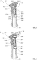
- the rocker 22 is mounted movable relative to the body 20 between a first position of locking in which the lever 22 positions the fastening element 123 in a first engagement configuration with the retaining element 21 (Cf. Figures 4 and 5 ) as will be specified below, and a second unlocking position in which the lever 22 positions the fastening element 123 in a second release configuration of the retaining element 21 (Cf. Figures 6 and 7 ).
- the handle 2 further comprises a return device 23 configured to exert on the lever 22 a return force tending to bring it from its unlocking position to its locking position.
- the return device 23 comprises a helical spring 231 disposed in a housing 200 formed in the body 20 of the handle 2.
- This housing 200 can be practiced in the middle part of the body 20 and opens for example on the rear of the handle 2, intended to be oriented towards the palm of the user's hand.
- a cover 26 can be provided to close this housing 200 and thus protect its content, and in particular the helical spring 231, from the external environment.
- the return device 23 further comprises a tie rod 232.
- the tie rod 232 is composed of a nut 2321, a threaded rod 2322 and a support 2323. Its construction is detailed in the figure 9 and is represented in simplified form in the sections of figures 1 to 8 .
- the nut 2321 constitutes a first end of the tie rod 232 and bears against a first end of the spring 231.
- the nut slides in the housing 200 in a direction substantially parallel to the longitudinal axis Z2 of the handle 2, without being able to rotate around its axis of revolution.
- the threaded rod 2322 is intended to be screwed onto the nut 2321.
- the threaded rod 2322 passes inside the spring 231 and through a through hole 203 of the body 20.
- the through hole 203 connects the housing 200 and the recess upper 201 along an axis substantially parallel to the longitudinal axis Z2 of the handle 2. It is configured so that the helical spring 2033 cannot pass through.
- the head of the threaded rod 2322 is assembled to the support 2323 and includes an impression for a tool ( figure 7 ).
- the support 2323 constitutes a second end of the tie rod 232 and is rotatably mounted on the rocker 22 around a transverse axis, via two pins 27. This produces a rotational connection to a degree of freedom between a first end of the tie rod 232 and flip-flop 22.
- This rotation link is configured jointly with the through hole 203 to allow the tie-rod 232 to accompany the flip-flop 22 in its tilting between its locking and unlocking positions, as illustrated by comparison of the positions of the tie-rod 232 in the through hole 203 on the figures 5 and 6 .
- the second end of the spring 231 bears against an upper internal face of the housing 200.
- the spring 231 is always mounted compressed, regardless of the position of the lever 22.
- the spring 231 exerts a force on the nut 2321 of the tie rod 232 which causes the rotation of the lever 22, via the second end of the tie rod 232, until the rocker stops against an internal face lower of the upper recess 201.
- This stable configuration corresponds to the first locking position of the lever 22.
- the spring 231 is compressed via the tie rod 232.
- the lever can rotate around its axis of rotation Y2 until it reaches an unstable position corresponding to the second unlocking position of the lever 22.
- the return device 23 returns the lever 22 to its stable position of locking.
- the handle 2 may further comprise a mechanism for adjusting the return force exerted by the return device 23.
- this adjustment device comprises the nut 2321 and the threaded rod 2322.
- the tie rod 232 is thus produced by two parts cooperating with each other so that the length of the tie rod is reduced as the threaded rod 2322 is screwed into the nut 2321. It is thus possible to adjust the compression level of the helical spring 231.
- To adjust the length of the tie rod introduces a tool into the impression of the head of the threaded rod. We then rotate the threaded rod in one direction or the other, depending on whether we want to lengthen or shorten the length of the tie rod.
- the nut 2321 does not rotate at the same time as the threaded rod 2322 because its rotation is blocked by the side walls of the housing 200.
- the flip-flop 22 comprises two parallel vertical walls separated by an empty space where part of the actuator 21 is housed.
- the vertical walls form, with the rest of the flip-flop, a stirrup.
- the shaft 25 fixed transversely to the body 20 passes through two orifices provided respectively on each of the vertical walls so as to allow the rotation of the rocker around the axis of rotation Y2.
- This arrangement between the body 20, the rocker 22 and the actuator 21 protects the rocker 22 and the actuator 21 from the external environment.
- the construction is thus both simple and robust for an increased life of the mechanism ensuring the joining between the item of clothing and the handle.
- the actuator 21 thus comprises the retaining element 210 corresponding to an extension of cylindrical shape.
- This retaining element 210 is intended to pass through the bore 1232 of the fixing element 123. It is this cooperation between these two elements which makes it possible to maintain the article of clothing 12 secured to the handle 2.
- the retaining element 210 and the rocker 22 are then configured so that the retaining member 210 can be introduced into the housing 220 of the rocker 22 by passing through the first bore 2211 of the rocker, when the rocker is in its locked position.
- the first bore 2211 is therefore a hole passing through the first lower wall 221 of the rocker 22.
- the rocker 22 is also configured so that the retaining element 210 is also introduced into the second bore 2221 of the rocker 22, when the rocker is in its locked position.
- the second bore 2221 is a hole which may or may not pass through the second upper wall 222 of the lever 22.
- the retaining element 210 is configured to be placed in the housing 220 of the rocker 22 via the first bore 2211 and as far as the second bore 2221, that the rocker 22 is in its locked position and when the actuator 21 is in a configuration for which the retaining element 210 is in its retaining position.
- This configuration is illustrated in Figures 4 and 5 .
- the rocker can be in an unlocked position, as illustrated in Figures 6 and 7 .
- the actuator may be in a configuration for which the retaining element 210 is in its release position, as illustrated in figures 2 and 3 .
- the actuator 21 will tilt in this configuration for which the retaining 210 is in its retaining position or the tilting of the rocker 22 in its locking position allows cooperation between the bore 1232 of the fixing element 123 with the retaining element 210 which has the effect of securing the fastening element with the retaining element in at least one direction. This cooperation corresponds to the engagement configuration of the fastening element 123 with the retaining element 210.
- the article of clothing 12 is then secured to the handle 2.
- the retaining element 210 is stressed in shear rather than bending when an effort is exerted on the article of clothing down the handle of the stick, or even in a direction substantially transverse to a longitudinal axis of the handle, preferably by forming an angle between - 45 ° and + 45 ° relative to a plane transverse to the longitudinal axis of the handle.
- the retaining element 210 can tilt in a release position.
- the actuator 21 carrying the retaining element 210 is pivotally mounted on the body 20 via the shaft 25.
- the rotation of the actuator 21 about the transverse axis Y2 therefore causes a displacement of the element retainer 210 so that the latter can engage or disengage from the housing 220, when the lever 22 is in its locked position.
- the actuator therefore makes it possible to switch the retaining element 210 between its retaining position ( figure 4 ) and its liberation position ( figure 3 ).
- the actuator 21 comprises a first arm 211 extending, from the axis of rotation Y2, in a substantially vertical direction, downward, along the body 20.
- the first arm 211 is dimensioned so that according to its angular position, around the axis of rotation Y2, it projects from the body 20, towards the front or enters a second anterior recess 204 of the body 20, extending downward and forward the yoke formed by the upper part 20a of the body 20. In the latter case, corresponding to the retaining position of the retaining element 210, only the front edge of the first arm 211 is flush with the front of the body 20.
- the first arm 211 may include a bearing surface 2111 for at least one finger of the hand.
- the bearing surface 2111 is positioned on the front edge of the first arm 211. It allows the user to pivot the retaining element 21 backwards with some of his fingers.
- the bearing surface 2111 extends over a length greater than one third of the length of the body 20 to allow the support of the index and middle fingers. This feature allows better handling of the actuator 21 by an intuitive actuation ergonomics. The little finger and the ring finger of the hand can come to bear against the front face of the lower part 20b of the body 20.
- the actuator 21 also comprises a second arm 212 extending, from the axis of rotation Y2, in a substantially horizontal direction, towards the rear, at the top of the body 20.
- the second arm 212 can be configured so that the user can press it, for example with his index finger or thumb, to rotate the actuator 21 so that the retaining member 210 switches from its retaining position to its release position.
- a bearing surface 2121 of the second arm 212 is flush with the top of the body 20 and of the lever 22, when the retaining element 210 is in its retaining position.
- the bearing surface 2121 can extend over a length greater than three-quarters of the width of the body 20, in a front-rear direction X, to allow the support of the thumb when the user holds the handle 2.
- the second arm 2121 penetrates more deeply inside the yoke formed by the upper part 20a of the body 20 and in the yoke formed by the rocker 22, when the user presses on the actuator 21. This characteristic allows better manipulation of the actuator 21 by intuitive actuation ergonomics.
- the retaining element 21 can extend the first arm 211 backwards and upwards, projecting into the space between the first and second arms 211, 212 of the actuator 21.
- the retaining element 21 is thus essentially included in the body 20, whatever the position of the actuator 21, which ensures its protection against the external environment.
- the handle 2 comprises an elastic member 24, for example a spring leaf, configured jointly with the body 20 and the actuator 21 to successively stabilize the actuator in two stable configurations: a first retaining configuration for which the retainer 210 is in its retainer position ( figure 4 ) and a second release configuration for which the retaining element 210 is in its release position ( figure 3 ).
- the second arm 212 of the actuator 21 abuts against the second wall 222 of the rocker 22 which bears on the lower internal face of the upper recess 201 of the body 20.
- the lever 22 is then in its locked position.
- the leaf spring 24 tends to keep the actuator 21 in abutment, in this second stable configuration.
- the retainer 210 When the retainer 210 is in its retaining position, the first arm 211 of the actuator 21 abuts against the first wall 221 of the rocker 22 which is held in its locking position by the return device 23.
- the leaf spring 24 tends to keep the actuator 21 in abutment, in this first stable configuration.
- the actuator 21 and the lever 22 are configured so that the retaining element 210 can only reach its release position if the lever 22 is in its locked position.
- the figures 2, 3 and 4 illustrate three successive steps allowing the fastening element 123 of the wrist strap 12 to be locked with the retaining element 210 of the handle 2, when the lever 22 is in its locking position, according to the embodiment of the invention illustrated in these figures.
- the user presses on the bearing surface 2121 of the second arm 212 of the actuator 21 so as to rotate it so that it reaches its second release configuration for which the retaining element 210 is in its release position, as illustrated in figure 2 .
- the lever 22 is then in its locked position. Therefore, it is possible to insert into the housing 220 of the rocker 22 the eyelet 1231 of the fixing element 123.
- the figure 3 illustrates the step for which the fixing element 123 is inserted into the housing 220.
- the fixing element 123, the actuator 21 and the rocker 22 are configured so that, when the eyelet 1231 abuts the bottom of the housing 220, the retaining element 210 of the actuator 21 is arranged in opposite bore 1232 of eyelet 1231.
- the user can then press on the bearing surface 2111 of the first arm 211 of the actuator 21 so as to rotate it so that it reaches its first retaining configuration for which the retaining element 210 is in its position retainer, as shown in figure 4 .
- the retaining element 210 thus passes through the bore 1232 of the eyelet 1231 and can come into engagement with the second bore 2221 formed in the second wall 222 of the housing 220 of the rocker 22.
- the fastening element 123 then cooperates with the retaining element 210 so as to hold the article of clothing integral with the handle.
- FIGS. 5 to 8 illustrate different successive steps for unlocking the fixing element 123 of the strap 12 of the retaining element 210 of the handle 2, according to the embodiment of the invention illustrated in these figures.
- a force opposite to the restoring force exerted by the return device 23 on the rocker 22 can be exerted on the rocker 22 via the fastening element 123 of the wrist strap 12.
- the latter can actually be pulled upwards, above the upper part 20a of the body 20 of the handle 2.
- This movement of the fastening element is for example observed when the user continues to move while the stick 11 remains trapped behind him, in particular by its end opposite to that receiving the handle 2.
- the rocker 22 is then able to switch from its locking position to its unlocking position as illustrated in the figure 6 .
- This movement of the lever 22 then drives the fixing element 123 into a position for which the eyelet 1231 disengages from the retaining element 210.
- the dimensioning of the spacing between the first and second arms 211, 212 of the actuator 21, of the rocker 22 and of the retaining element 210 makes it possible to obtain this configuration in which the rocker is in its unlocked position.
- the lever 22 reaches this unlocking position, it has rotated enough for the retaining element 210 to disengage from the second bore 2221 formed in the second wall 222 of the housing 220 and entirely from the housing 220.
- This position of the fixing corresponds to the release configuration of the fixing element with the retaining element.
- the fixing element 123 can then disengage from the housing 220 of the rocker 22, as illustrated in the figure 7 .
- the article of clothing is then detached from the handle. Once the fixing element 123 has been removed, the lever 22 is no longer held in its unlocked position.
- the lever 22 then returns to its locked position under the action of the return device 23, as illustrated in the figure 8 .
- the invention is not limited to the embodiment described above. Other variants can be envisaged.
- the retaining element 210 and the rocker 22 are described above as being rotatably mounted relative to the body 20 of the handle 2. However, it can be envisaged that the movement of at least one of the retainer and the either a translational movement or a movement combining rotation and translation.
- the retaining element 210 is described above as being mounted movable relative to the body 20 of the handle 2. However, it is envisaged that the retaining element 210 is fixed relative to the body 20 of the handle 2, and is more particularly fixed in its retaining position.
- the locking of the fastening element 123 of the wrist strap 12 with the retaining element 21 of the handle 2 can then comprise the successive stages, relatively well illustrated by successively traversing the figures 8 , 7 , 6 and 5 (except that the arrows illustrating the movement of the fixing element 123 of the wrist strap 12, as well as the curved shape of this fixing element 123, do not correctly illustrate the following). In these figures, the retaining element 210 remains in its retaining position.
Landscapes
- Purses, Travelling Bags, Baskets, Or Suitcases (AREA)
Claims (15)
- Griff (2) für einen Stock (11), wobei der Griff umfasst:∘ einen Körper (20),∘ ein Halteelement (210), das zusammen mit dem Körper ausgebildet ist, wobei das Halteelement in der Lage ist, mit dem Befestigungselement (123) zusammenzuwirken, um das Befestigungselement mit dem Halteelement in wenigstens einer Richtung fest zu verbinden, und∘ ein Kippglied (22), das zusammen mit dem Körper ausgebildet ist, wobei das Kippglied in Bezug auf den Körper beweglich angebracht ist zwischen:- einer Verriegelungsposition, in welcher das Kippglied in der Lage ist, das Befestigungselement (123) in eine Konfiguration der Verrastung mit dem Halteelement zu positionieren, und- einer Entriegelungsposition, in welcher das Kippglied in der Lage ist, das Befestigungselement (123) in eine Konfiguration der Ausrastung aus dem Halteelement zu positionieren,
wobei der Griff außerdem eine Rückstellvorrichtung (23) umfasst, die dafür ausgelegt ist, auf das Kippglied eine Rückstellkraft auszuüben, die bestrebt ist, es aus seiner Entriegelungsposition in seine Verriegelungsposition zurückzubewegen, dadurch gekennzeichnet, dass das Kippglied eine Aufnahme (220) umfasst, die dafür ausgelegt ist, das Befestigungselement (123) des Bekleidungsartikels wenigstens teilweise aufzunehmen. - Griff (2) für einen Stock (11) nach dem vorhergehenden Anspruch, wobei der Griff einen Mechanismus zur Regelung (2321, 2322) der Rückstellkraft umfasst, die von der Rückstellvorrichtung ausgeübt wird.
- Griff (2) für einen Stock (11) nach einem der vorhergehenden Ansprüche, wobei die Aufnahme derart in dem Kippglied angeordnet ist, dass sich das Befestigungselement in einer Richtung im Wesentlichen quer zu einer Längsachse (Z2) des Griffs in sie einfügt, wobei es vorzugsweise einen Winkel zwischen -45° und +45° in Bezug auf eine quer zur Längsachse des Griffs verlaufende Ebene bildet.
- Griff (2) für einen Stock (11) nach einem der vorhergehenden Ansprüche, wobei das Halteelement in Bezug auf den Körper beweglich angebracht ist zwischen:- einer Halteposition, in welcher das Halteelement teilweise in der Aufnahme des Kippglieds angeordnet ist, so dass es das Befestigungselement verriegelt, wenn sich das Kippglied in seiner Verriegelungsposition befindet und das Befestigungselement in die Aufnahme eingefügt ist, und- einer Freigabeposition, in welcher kein Teil des Halteelements in der Aufnahme des Kippglieds angeordnet ist, wenn sich das Kippglied in seiner Verriegelungsposition befindet.
- Griff (2) für einen Stock (11) nach einem der vorhergehenden Ansprüche, wobei das Kippglied eine erste, durchgehende Bohrung (2211) und eine zweite, durchgehende oder nicht durchgehende Bohrung (2221) umfasst, die in einer ersten bzw. zweiten Wand (221 und 222) der Aufnahme (220) des Kippglieds ausgebildet sind, wobei das Halteelement so gestaltet ist, dass es in die Aufnahme über die erste Bohrung und bis in die zweite Bohrung eingreifen kann, wenn sich das Kippglied in seiner Verriegelungsposition befindet.
- Griff (2) für einen Stock (11) nach einem der vorhergehenden Ansprüche, wobei das Kippglied in der Lage ist, unter der Wirkung einer Kraft, die zu der Rückstellkraft, welche die Rückstellvorrichtung auf das Kippglied ausübt, entgegengesetzt ist und durch das Befestigungselement auf das Kippglied übertragen wird, aus seiner Verriegelungsposition in seine Entriegelungsposition zu kippen, wobei die Rückstellvorrichtung so gestaltet ist, dass die Rückstellkraft, welche sie auf das Kippglied ausübt, zu einem unteren Teil des Stocks hin gerichtet ist.
- Griff (2) für einen Stock (11) nach einem der vorhergehenden Ansprüche, wobei das Halteelement und das Kippglied drehbar um ein und dieselbe Drehachse (Y2) am Körper des Griffs angebracht sind.
- Griff (2) für einen Stock (11) nach einem der vorhergehenden Ansprüche, wobei das Befestigungselement (123) eine Öse (1231) aus Kunststoff oder Metall umfasst, die eine Bohrung (1232) begrenzt.
- Griff (2) für einen Stock (11) nach einem der vorhergehenden Ansprüche, wobei die Rückstellvorrichtung (23) eine Feder (231) und einen Zugstab (232) umfasst, wobei der Zugstab ein erstes Ende der Feder mit dem Kippglied (22) verbindet, während das zweite Ende der Feder am Körper (20) anliegt.
- Griff (2) für einen Stock (11) nach einem der vorhergehenden Ansprüche, wobei die Aufnahme (220) des Kippglieds von einer ersten, unteren Wand (221), in welcher eine erste Bohrung (2211) ausgebildet ist, und von einer zweiten, oberen Wand (222) begrenzt wird.
- Griff (2) für einen Stock (11) nach dem vorhergehenden Anspruch, wobei eine zweite Bohrung (2221) in der zweiten, oberen Wand (222) ausgebildet ist.
- Griff (2) für einen Stock (11) nach einem der Ansprüche 10 oder 11, wobei das Halteelement (210) dafür ausgelegt ist, über die erste Bohrung (2211) in der Aufnahme (220) des Kippglieds (22) angeordnet zu werden, wenn sich das Halteelement in seiner Halteposition befindet und wenn sich das Kippglied (22) in seiner Verriegelungsposition befindet.
- Griff (2) für einen Stock (11) nach einem der vorhergehenden Ansprüche, wobei das Halteelement von einem Stellglied (21) getragen wird, das von einem elastischen Organ (24) beaufschlagt wird, um das Stellglied nacheinander in zwei stabilen Konfigurationen zu stabilisieren: einer ersten Haltekonfiguration, für welche sich das Halteelement (210) in seiner Halteposition befindet, und einer zweiten Freigabekonfiguration, für welche sich das Halteelement (210) in seiner Freigabeposition befindet.
- Stock (11), welcher mit einem Griff (2) nach einem der vorhergehenden Ansprüche ausgestattet ist.
- Einheit (1) Stock / Bekleidungsartikel, welche umfasst:- einen Stock (11), der mit einem Griff (2) nach einem der Ansprüche 1 bis 13 versehen ist;- einen Bekleidungsartikel (12), der dazu bestimmt ist, die Hand eines Benutzers wenigstens teilweise zu bedecken, wobei der Bekleidungsartikel mit einem Befestigungselement (123) zur Befestigung an dem Griff versehen ist.
Applications Claiming Priority (1)
| Application Number | Priority Date | Filing Date | Title |
|---|---|---|---|
| FR1601792A FR3060403B1 (fr) | 2016-12-15 | 2016-12-15 | Ensemble baton/article vestimentaire |
Publications (2)
| Publication Number | Publication Date |
|---|---|
| EP3335772A1 EP3335772A1 (de) | 2018-06-20 |
| EP3335772B1 true EP3335772B1 (de) | 2020-02-19 |
Family
ID=58054178
Family Applications (1)
| Application Number | Title | Priority Date | Filing Date |
|---|---|---|---|
| EP17206423.0A Active EP3335772B1 (de) | 2016-12-15 | 2017-12-11 | Einheit stock / bekleidungsartikel |
Country Status (2)
| Country | Link |
|---|---|
| EP (1) | EP3335772B1 (de) |
| FR (1) | FR3060403B1 (de) |
Family Cites Families (3)
| Publication number | Priority date | Publication date | Assignee | Title |
|---|---|---|---|---|
| DE19636852C1 (de) * | 1996-09-11 | 1998-02-12 | Klaus Lenhart | Stockgriff mit Handschlaufe |
| JP5116484B2 (ja) * | 2004-12-23 | 2013-01-09 | レキスポルト アーゲー | ポールグリップに固定する、特に手袋などの、手保持装置 |
| FR2999445B1 (fr) * | 2012-12-19 | 2015-02-13 | Salomon Sas | Poignee de baton |
-
2016
- 2016-12-15 FR FR1601792A patent/FR3060403B1/fr not_active Expired - Fee Related
-
2017
- 2017-12-11 EP EP17206423.0A patent/EP3335772B1/de active Active
Non-Patent Citations (1)
| Title |
|---|
| None * |
Also Published As
| Publication number | Publication date |
|---|---|
| EP3335772A1 (de) | 2018-06-20 |
| FR3060403B1 (fr) | 2019-07-12 |
| FR3060403A1 (fr) | 2018-06-22 |
Similar Documents
| Publication | Publication Date | Title |
|---|---|---|
| EP2745888B1 (de) | Stockgriff | |
| EP2687275B1 (de) | Vordere Haltevorrichtungen eines Gleitbrettes | |
| EP3260178B1 (de) | Fersenhalter zur befestigung eines schuhes auf einem snowboard | |
| CA1331388C (fr) | Fixation de ski de fond de type charniere | |
| FR2661076A1 (fr) | Chaussure de ski a tige articulee avec position verrouillee de descente et position liberee de repos ou de marche. | |
| EP2070433B1 (de) | Sportschuh mit Blockiervorrichtung | |
| EP2486817B1 (de) | Sportschuh mit angelenktem Schaft für eine Laufstellung | |
| FR2976638A1 (fr) | Mousqueton de securite | |
| CA2003596A1 (fr) | Dispositif de liaison d'une poignee notamment de d'un baton de ski a la main d'un utilisateur | |
| EP3416732B1 (de) | Fersenhalter für ein skischuh mit einem einstiegspedal, wobei das einstiegspedal relativ zum fernsehenhalter mobil ist. | |
| EP2883583B1 (de) | Stock-Schlaufen-Einheit | |
| EP3437703B1 (de) | Bremsvorrichtung für tourenski | |
| EP3827887B1 (de) | Hinterbacken für tourenskier | |
| EP4424392B1 (de) | Bodenstützvorrichtung mit einem stock und einer handschlaufe | |
| FR3060403B1 (fr) | Ensemble baton/article vestimentaire | |
| EP1813321A1 (de) | Befestigungsschlinge mit Element zum sicheren Anlegen | |
| EP2386333B1 (de) | Befestigungselement mit einstellbarer Position auf einem Schneegleitbrett | |
| EP3184155B1 (de) | Skibindung | |
| CH619144A5 (de) | ||
| EP3097006B1 (de) | Fahrradpedal mit automatischer arretierung und lösung | |
| EP0495737B1 (de) | Skibremse | |
| FR3072884A1 (fr) | Butee de dispositif de fixation d'une chaussure | |
| EP0761114B1 (de) | Skischuh | |
| EP4555889A1 (de) | Verriegelungsvorrichtung für einen sportschuh | |
| EP1785172A1 (de) | Sportschuh-Bindungsvorrichtung auf einem Gleitbrett |
Legal Events
| Date | Code | Title | Description |
|---|---|---|---|
| PUAI | Public reference made under article 153(3) epc to a published international application that has entered the european phase |
Free format text: ORIGINAL CODE: 0009012 |
|
| STAA | Information on the status of an ep patent application or granted ep patent |
Free format text: STATUS: THE APPLICATION HAS BEEN PUBLISHED |
|
| AK | Designated contracting states |
Kind code of ref document: A1 Designated state(s): AL AT BE BG CH CY CZ DE DK EE ES FI FR GB GR HR HU IE IS IT LI LT LU LV MC MK MT NL NO PL PT RO RS SE SI SK SM TR |
|
| AX | Request for extension of the european patent |
Extension state: BA ME |
|
| STAA | Information on the status of an ep patent application or granted ep patent |
Free format text: STATUS: REQUEST FOR EXAMINATION WAS MADE |
|
| 17P | Request for examination filed |
Effective date: 20181214 |
|
| GRAP | Despatch of communication of intention to grant a patent |
Free format text: ORIGINAL CODE: EPIDOSNIGR1 |
|
| STAA | Information on the status of an ep patent application or granted ep patent |
Free format text: STATUS: GRANT OF PATENT IS INTENDED |
|
| INTG | Intention to grant announced |
Effective date: 20191002 |
|
| GRAS | Grant fee paid |
Free format text: ORIGINAL CODE: EPIDOSNIGR3 |
|
| GRAA | (expected) grant |
Free format text: ORIGINAL CODE: 0009210 |
|
| STAA | Information on the status of an ep patent application or granted ep patent |
Free format text: STATUS: THE PATENT HAS BEEN GRANTED |
|
| AK | Designated contracting states |
Kind code of ref document: B1 Designated state(s): AL AT BE BG CH CY CZ DE DK EE ES FI FR GB GR HR HU IE IS IT LI LT LU LV MC MK MT NL NO PL PT RO RS SE SI SK SM TR |
|
| REG | Reference to a national code |
Ref country code: CH Ref legal event code: EP |
|
| REG | Reference to a national code |
Ref country code: DE Ref legal event code: R096 Ref document number: 602017011937 Country of ref document: DE |
|
| REG | Reference to a national code |
Ref country code: AT Ref legal event code: REF Ref document number: 1234266 Country of ref document: AT Kind code of ref document: T Effective date: 20200315 |
|
| REG | Reference to a national code |
Ref country code: IE Ref legal event code: FG4D Free format text: LANGUAGE OF EP DOCUMENT: FRENCH |
|
| REG | Reference to a national code |
Ref country code: NL Ref legal event code: MP Effective date: 20200219 |
|
| PG25 | Lapsed in a contracting state [announced via postgrant information from national office to epo] |
Ref country code: NO Free format text: LAPSE BECAUSE OF FAILURE TO SUBMIT A TRANSLATION OF THE DESCRIPTION OR TO PAY THE FEE WITHIN THE PRESCRIBED TIME-LIMIT Effective date: 20200519 Ref country code: FI Free format text: LAPSE BECAUSE OF FAILURE TO SUBMIT A TRANSLATION OF THE DESCRIPTION OR TO PAY THE FEE WITHIN THE PRESCRIBED TIME-LIMIT Effective date: 20200219 Ref country code: RS Free format text: LAPSE BECAUSE OF FAILURE TO SUBMIT A TRANSLATION OF THE DESCRIPTION OR TO PAY THE FEE WITHIN THE PRESCRIBED TIME-LIMIT Effective date: 20200219 |
|
| REG | Reference to a national code |
Ref country code: LT Ref legal event code: MG4D |
|
| PG25 | Lapsed in a contracting state [announced via postgrant information from national office to epo] |
Ref country code: HR Free format text: LAPSE BECAUSE OF FAILURE TO SUBMIT A TRANSLATION OF THE DESCRIPTION OR TO PAY THE FEE WITHIN THE PRESCRIBED TIME-LIMIT Effective date: 20200219 Ref country code: BG Free format text: LAPSE BECAUSE OF FAILURE TO SUBMIT A TRANSLATION OF THE DESCRIPTION OR TO PAY THE FEE WITHIN THE PRESCRIBED TIME-LIMIT Effective date: 20200519 Ref country code: IS Free format text: LAPSE BECAUSE OF FAILURE TO SUBMIT A TRANSLATION OF THE DESCRIPTION OR TO PAY THE FEE WITHIN THE PRESCRIBED TIME-LIMIT Effective date: 20200619 Ref country code: SE Free format text: LAPSE BECAUSE OF FAILURE TO SUBMIT A TRANSLATION OF THE DESCRIPTION OR TO PAY THE FEE WITHIN THE PRESCRIBED TIME-LIMIT Effective date: 20200219 Ref country code: LV Free format text: LAPSE BECAUSE OF FAILURE TO SUBMIT A TRANSLATION OF THE DESCRIPTION OR TO PAY THE FEE WITHIN THE PRESCRIBED TIME-LIMIT Effective date: 20200219 Ref country code: GR Free format text: LAPSE BECAUSE OF FAILURE TO SUBMIT A TRANSLATION OF THE DESCRIPTION OR TO PAY THE FEE WITHIN THE PRESCRIBED TIME-LIMIT Effective date: 20200520 |
|
| PG25 | Lapsed in a contracting state [announced via postgrant information from national office to epo] |
Ref country code: NL Free format text: LAPSE BECAUSE OF FAILURE TO SUBMIT A TRANSLATION OF THE DESCRIPTION OR TO PAY THE FEE WITHIN THE PRESCRIBED TIME-LIMIT Effective date: 20200219 |
|
| PG25 | Lapsed in a contracting state [announced via postgrant information from national office to epo] |
Ref country code: CZ Free format text: LAPSE BECAUSE OF FAILURE TO SUBMIT A TRANSLATION OF THE DESCRIPTION OR TO PAY THE FEE WITHIN THE PRESCRIBED TIME-LIMIT Effective date: 20200219 Ref country code: RO Free format text: LAPSE BECAUSE OF FAILURE TO SUBMIT A TRANSLATION OF THE DESCRIPTION OR TO PAY THE FEE WITHIN THE PRESCRIBED TIME-LIMIT Effective date: 20200219 Ref country code: ES Free format text: LAPSE BECAUSE OF FAILURE TO SUBMIT A TRANSLATION OF THE DESCRIPTION OR TO PAY THE FEE WITHIN THE PRESCRIBED TIME-LIMIT Effective date: 20200219 Ref country code: SK Free format text: LAPSE BECAUSE OF FAILURE TO SUBMIT A TRANSLATION OF THE DESCRIPTION OR TO PAY THE FEE WITHIN THE PRESCRIBED TIME-LIMIT Effective date: 20200219 Ref country code: PT Free format text: LAPSE BECAUSE OF FAILURE TO SUBMIT A TRANSLATION OF THE DESCRIPTION OR TO PAY THE FEE WITHIN THE PRESCRIBED TIME-LIMIT Effective date: 20200712 Ref country code: DK Free format text: LAPSE BECAUSE OF FAILURE TO SUBMIT A TRANSLATION OF THE DESCRIPTION OR TO PAY THE FEE WITHIN THE PRESCRIBED TIME-LIMIT Effective date: 20200219 Ref country code: EE Free format text: LAPSE BECAUSE OF FAILURE TO SUBMIT A TRANSLATION OF THE DESCRIPTION OR TO PAY THE FEE WITHIN THE PRESCRIBED TIME-LIMIT Effective date: 20200219 Ref country code: SM Free format text: LAPSE BECAUSE OF FAILURE TO SUBMIT A TRANSLATION OF THE DESCRIPTION OR TO PAY THE FEE WITHIN THE PRESCRIBED TIME-LIMIT Effective date: 20200219 Ref country code: LT Free format text: LAPSE BECAUSE OF FAILURE TO SUBMIT A TRANSLATION OF THE DESCRIPTION OR TO PAY THE FEE WITHIN THE PRESCRIBED TIME-LIMIT Effective date: 20200219 |
|
| REG | Reference to a national code |
Ref country code: AT Ref legal event code: MK05 Ref document number: 1234266 Country of ref document: AT Kind code of ref document: T Effective date: 20200219 |
|
| REG | Reference to a national code |
Ref country code: DE Ref legal event code: R097 Ref document number: 602017011937 Country of ref document: DE |
|
| PLBE | No opposition filed within time limit |
Free format text: ORIGINAL CODE: 0009261 |
|
| STAA | Information on the status of an ep patent application or granted ep patent |
Free format text: STATUS: NO OPPOSITION FILED WITHIN TIME LIMIT |
|
| 26N | No opposition filed |
Effective date: 20201120 |
|
| PG25 | Lapsed in a contracting state [announced via postgrant information from national office to epo] |
Ref country code: AT Free format text: LAPSE BECAUSE OF FAILURE TO SUBMIT A TRANSLATION OF THE DESCRIPTION OR TO PAY THE FEE WITHIN THE PRESCRIBED TIME-LIMIT Effective date: 20200219 Ref country code: IT Free format text: LAPSE BECAUSE OF FAILURE TO SUBMIT A TRANSLATION OF THE DESCRIPTION OR TO PAY THE FEE WITHIN THE PRESCRIBED TIME-LIMIT Effective date: 20200219 |
|
| PG25 | Lapsed in a contracting state [announced via postgrant information from national office to epo] |
Ref country code: PL Free format text: LAPSE BECAUSE OF FAILURE TO SUBMIT A TRANSLATION OF THE DESCRIPTION OR TO PAY THE FEE WITHIN THE PRESCRIBED TIME-LIMIT Effective date: 20200219 Ref country code: SI Free format text: LAPSE BECAUSE OF FAILURE TO SUBMIT A TRANSLATION OF THE DESCRIPTION OR TO PAY THE FEE WITHIN THE PRESCRIBED TIME-LIMIT Effective date: 20200219 |
|
| REG | Reference to a national code |
Ref country code: CH Ref legal event code: PL |
|
| PG25 | Lapsed in a contracting state [announced via postgrant information from national office to epo] |
Ref country code: MC Free format text: LAPSE BECAUSE OF FAILURE TO SUBMIT A TRANSLATION OF THE DESCRIPTION OR TO PAY THE FEE WITHIN THE PRESCRIBED TIME-LIMIT Effective date: 20200219 |
|
| REG | Reference to a national code |
Ref country code: BE Ref legal event code: MM Effective date: 20201231 |
|
| PG25 | Lapsed in a contracting state [announced via postgrant information from national office to epo] |
Ref country code: IE Free format text: LAPSE BECAUSE OF NON-PAYMENT OF DUE FEES Effective date: 20201211 Ref country code: LU Free format text: LAPSE BECAUSE OF NON-PAYMENT OF DUE FEES Effective date: 20201211 |
|
| PG25 | Lapsed in a contracting state [announced via postgrant information from national office to epo] |
Ref country code: CH Free format text: LAPSE BECAUSE OF NON-PAYMENT OF DUE FEES Effective date: 20201231 Ref country code: LI Free format text: LAPSE BECAUSE OF NON-PAYMENT OF DUE FEES Effective date: 20201231 |
|
| PG25 | Lapsed in a contracting state [announced via postgrant information from national office to epo] |
Ref country code: TR Free format text: LAPSE BECAUSE OF FAILURE TO SUBMIT A TRANSLATION OF THE DESCRIPTION OR TO PAY THE FEE WITHIN THE PRESCRIBED TIME-LIMIT Effective date: 20200219 Ref country code: MT Free format text: LAPSE BECAUSE OF FAILURE TO SUBMIT A TRANSLATION OF THE DESCRIPTION OR TO PAY THE FEE WITHIN THE PRESCRIBED TIME-LIMIT Effective date: 20200219 Ref country code: CY Free format text: LAPSE BECAUSE OF FAILURE TO SUBMIT A TRANSLATION OF THE DESCRIPTION OR TO PAY THE FEE WITHIN THE PRESCRIBED TIME-LIMIT Effective date: 20200219 |
|
| PG25 | Lapsed in a contracting state [announced via postgrant information from national office to epo] |
Ref country code: MK Free format text: LAPSE BECAUSE OF FAILURE TO SUBMIT A TRANSLATION OF THE DESCRIPTION OR TO PAY THE FEE WITHIN THE PRESCRIBED TIME-LIMIT Effective date: 20200219 Ref country code: AL Free format text: LAPSE BECAUSE OF FAILURE TO SUBMIT A TRANSLATION OF THE DESCRIPTION OR TO PAY THE FEE WITHIN THE PRESCRIBED TIME-LIMIT Effective date: 20200219 |
|
| PG25 | Lapsed in a contracting state [announced via postgrant information from national office to epo] |
Ref country code: BE Free format text: LAPSE BECAUSE OF NON-PAYMENT OF DUE FEES Effective date: 20201231 |
|
| GBPC | Gb: european patent ceased through non-payment of renewal fee |
Effective date: 20211211 |
|
| PG25 | Lapsed in a contracting state [announced via postgrant information from national office to epo] |
Ref country code: GB Free format text: LAPSE BECAUSE OF NON-PAYMENT OF DUE FEES Effective date: 20211211 |
|
| P01 | Opt-out of the competence of the unified patent court (upc) registered |
Effective date: 20240315 |
|
| PGFP | Annual fee paid to national office [announced via postgrant information from national office to epo] |
Ref country code: DE Payment date: 20251126 Year of fee payment: 9 |
|
| PGFP | Annual fee paid to national office [announced via postgrant information from national office to epo] |
Ref country code: FR Payment date: 20251120 Year of fee payment: 9 |