EP2070652B1 - Appareil de meulage des bords de rondelles utilisant un outil de dressage de meule et son procédé de fabrication, et procédé de fabrication de meule - Google Patents
Appareil de meulage des bords de rondelles utilisant un outil de dressage de meule et son procédé de fabrication, et procédé de fabrication de meule Download PDFInfo
- Publication number
- EP2070652B1 EP2070652B1 EP08021666.6A EP08021666A EP2070652B1 EP 2070652 B1 EP2070652 B1 EP 2070652B1 EP 08021666 A EP08021666 A EP 08021666A EP 2070652 B1 EP2070652 B1 EP 2070652B1
- Authority
- EP
- European Patent Office
- Prior art keywords
- grinding wheel
- grinding
- groove
- truer
- fine
- Prior art date
- Legal status (The legal status is an assumption and is not a legal conclusion. Google has not performed a legal analysis and makes no representation as to the accuracy of the status listed.)
- Active
Links
Images


Classifications
-
- B—PERFORMING OPERATIONS; TRANSPORTING
- B24—GRINDING; POLISHING
- B24B—MACHINES, DEVICES, OR PROCESSES FOR GRINDING OR POLISHING; DRESSING OR CONDITIONING OF ABRADING SURFACES; FEEDING OF GRINDING, POLISHING, OR LAPPING AGENTS
- B24B53/00—Devices or means for dressing or conditioning abrasive surfaces
- B24B53/06—Devices or means for dressing or conditioning abrasive surfaces of profiled abrasive wheels
- B24B53/07—Devices or means for dressing or conditioning abrasive surfaces of profiled abrasive wheels by means of forming tools having a shape complementary to that to be produced, e.g. blocks, profile rolls
-
- B—PERFORMING OPERATIONS; TRANSPORTING
- B24—GRINDING; POLISHING
- B24B—MACHINES, DEVICES, OR PROCESSES FOR GRINDING OR POLISHING; DRESSING OR CONDITIONING OF ABRADING SURFACES; FEEDING OF GRINDING, POLISHING, OR LAPPING AGENTS
- B24B9/00—Machines or devices designed for grinding edges or bevels on work or for removing burrs; Accessories therefor
- B24B9/02—Machines or devices designed for grinding edges or bevels on work or for removing burrs; Accessories therefor characterised by a special design with respect to properties of materials specific to articles to be ground
- B24B9/06—Machines or devices designed for grinding edges or bevels on work or for removing burrs; Accessories therefor characterised by a special design with respect to properties of materials specific to articles to be ground of non-metallic inorganic material, e.g. stone, ceramics, porcelain
- B24B9/065—Machines or devices designed for grinding edges or bevels on work or for removing burrs; Accessories therefor characterised by a special design with respect to properties of materials specific to articles to be ground of non-metallic inorganic material, e.g. stone, ceramics, porcelain of thin, brittle parts, e.g. semiconductors, wafers
-
- B—PERFORMING OPERATIONS; TRANSPORTING
- B24—GRINDING; POLISHING
- B24D—TOOLS FOR GRINDING, BUFFING OR SHARPENING
- B24D18/00—Manufacture of grinding tools or other grinding devices, e.g. wheels, not otherwise provided for
-
- B—PERFORMING OPERATIONS; TRANSPORTING
- B24—GRINDING; POLISHING
- B24D—TOOLS FOR GRINDING, BUFFING OR SHARPENING
- B24D5/00—Bonded abrasive wheels, or wheels with inserted abrasive blocks, designed for acting only by their periphery; Bushings or mountings therefor
Definitions
- the present invention relates to a wafer edge grinding apparatus using a grinding wheel truing tool, its manufacturing method, and a method for manufacturing a grinding wheel that can easily form or compensate a groove of a wafer edge grinding wheel to improve durability of the grinding wheel and process a wafer edge in conformity with quality specifications.
- a technology for grinding a round of an edge of a semiconductor wafer includes vertical grinding and helical grinding.
- the vertical grinding technology rotates a grinding wheel having a groove on a level with a surface of a semiconductor wafer, contacts a surface of the groove with an edge of the semiconductor wafer and grinds the edge of the semiconductor wafer using shape and roughness of the groove.
- the helical grinding technology rotates a grinding wheel having a groove at a predetermined angle relative to a surface of a semiconductor wafer, contacts a surface of the groove with an edge of the semiconductor wafer and grinds the edge of the semiconductor wafer.
- a grinding wheel In grinding an edge of a semiconductor wafer using the above-mentioned technology, a grinding wheel has a groove, of which shape corresponds to that of the edge of the semiconductor wafer, in conformity with the predetermined quality specifications.
- the grinding wheel in particular, the groove is made of a metal bond or a resin bond.
- a grinding wheel having a metal bond groove has excellent wear resistance, and thus, although the number of times of wafer edge grinding increases, the grinding wheel suffers a little change in shape of the groove caused by wear and eliminates the need to true or dress the groove during wafer edge grinding.
- the grinding wheel having the metal bond groove forms a damaged layer of a predetermined depth from the surface of the wafer edge and generates a fine scratch such as a wheel mark on the surface of the wafer edge, and thus does not meet customer demands for wafer surface quality.
- a grinding wheel having a resin bond groove guarantees a good grinding quality, but has a slow grinding speed and a poor wear resistance of the groove, and consequently suffers a change in shape of the groove during wafer edge grinding.
- the resin bond groove needs truing or dressing in a predetermined cycle.
- wafer edge grinding is complicated, a diameter of the grinding wheel is limited due to a wheel balance problem and life of a spindle is reduced.
- 'truing' means, when the shape of a groove of a grinding wheel is changed, restoring the shape of the groove using a truing tool (hereinafter referred to as a truer, and a conventional truer has similar thickness and diameter to a wafer) having an edge of a shape corresponding to a standard shape of the groove.
- 'Dressing' means removing grinding swarf that may be loaded in between exposed grits of a truer, and removing chips caught in exposed pores using a diamond dresser to expose new grits to the surface, thereby restoring a grinding performance.
- a conventional wafer edge grinding process performs double grinding that grinds (rough-grinds) a considerable amount of edge of a semiconductor wafer using a grinding wheel having a metal bond groove and then grinds (fine-grinds) the edge of the semiconductor wafer using a grinding wheel having a resin bond groove to remove a fine scratch such as a wheel mark.
- This process can simultaneously make up for grinding quality reduction pointed out as a disadvantage of the metal bond groove, and life reduction caused by a low wear resistance, pointed out as a disadvantage of the resin bond groove.
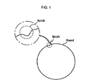
- FIG. 1 is a view illustrating a notch and a round of a wafer edge.
- the conventional wafer edge grinding apparatus 10 includes a chuck operating unit 20 for fixing and rotating a wafer W, a grinding wheel 30 for grinding an edge of the wafer W, and a truer S for truing grooves 32' and 34' of the grinding wheel 30.
- the grinding wheel 30 includes rough-grinding wheels 31 and 33 having metal bond grooves for rough-grinding a notch and a round of the wafer W, and fine-grinding wheels 32 and 34 having resin bond grooves for fine-grinding a notch and a round of the wafer W.
- the rough-grinding wheels 31 and 33 include a round rough-grinding wheel 31 for rough-grinding a round of the wafer W, and a notch rough-grinding wheel 33 for rough-grinding a notch of the wafer W.
- the fine-grinding wheels 32 and 34 include a notch fine-grinding wheel 32 for fine-grinding a notch of the wafer W, and a round fine-grinding wheel 34 for fine-grinding a round of the wafer W.
- the round fine-grinding wheel 34 is slanted at a predetermined angle, and thus it is also referred to as a helical wheel.
- the grinding wheel 30 rotates in the direction equal or opposite to a rotation direction of the wafer W, and contacts with the edge of the wafer W to grind the edge of the wafer W using shape and roughness of the groove.
- the worn grooves 32' and 34' should be trued.
- the truing is made by the truer S having shape and dimension corresponding to thickness and diameter of the wafer W.
- a wafer edge grinding process using the grinding apparatus 10 and a truing process using the truer S are described as follows.
- the wafer edge grinding process first, center, thickness and notch of a wafer W are measured. Next, the wafer W is loaded on a rotatable chuck 21 (mounted on a processing stage), and a round of the wafer W is rough-ground. Subsequently, a notch of the wafer W is rough-ground and fine-ground, and the round of the wafer W is fine-ground. Finally, the wafer W is unloaded.
- center and thickness of the truer S are measured.
- the truer S is mounted on the chuck 21, and compensated by a truer compensating tool embedded in the round rough-grinding wheel 31.
- the groove 32' of the notch fine-grinding wheel 32 or the groove 34' of the round fine-grinding wheel 34 is selectively trued by the compensated truer S.
- the notch fine-grinding wheel 32 has a plurality of grooves 32' on the surface thereof.
- the grooves 32' fine-grind the wafer W.
- the grooves 32' are trued by the truer S.
- the notch fine-grinding wheel 32 grinds upper and lower slanted surfaces of the edge of the wafer W separately, and uses an air bearing with a spindle mounting the wheel 32. Due to these characteristics, when the number of times of wafer edge processing and truing exceeds a predetermined number, a wear unbalance phenomenon occurs to the notch fine-grinding wheel 32.
- the wear unbalance phenomenon is resulted from an increase in grinding amount by a volume indicated by diagonal lines (see FIG.
- a notch of the first wafer W and a notch of the second wafer W are formed in different shapes. That is, there is a predetermined difference in grinding amount between a wafer of an odd number and a wafer of an even number, resulting in wear unbalance.
- the round fine-grinding wheel 34 has a spindle mounted at a predetermined angle, for example 8°.
- a new groove has a shape that is not in conformity with the shape quality specification.
- a new groove should be trued by the truer S. If the new groove is not trued, because an edge of a wafer W is ground by a groove that is not in conformity with the shape quality specification, the edge of the wafer W has a shape that does not meet the shape quality specification as shown in FIG. 7 , and consequently the wafer W is regarded as a faulty product. Therefore, after a grinding wheel or its groove is replaced by a new one, a new groove should be trued by the truer S to meet the shape quality specification for wafer edge.
- the groove 34' is worn down and a wheel diameter at the groove 34' is reduced.
- a wear amount reaches a predetermined amount (1mm in radius, 30 times of truings)
- the use of the corresponding groove 34' is stopped to prevent an over-grinding phenomenon that the wafer edge is over-ground, and the groove 34' or the grinding wheel 34 is replaced by a new one.
- an over-grinding phenomenon may occur due to a small change in Z-axis or flatness of a wafer or a small change in flatness of a chuck that may be caused by impurities on the surface of the chuck. This is why a grinding wheel or its groove is replaced by a new one.
- the over-grinding problem generally comes to the notch fine-grinding wheel 32 and the round fine-grinding wheel 34.
- the over-grinding is recognized by an edge profiler or a microscope with a scale.
- the upper and lower bevel values are measured, in the case that the values exceed a predetermined range, it is determined as over-grinding, and a subsequent process is performed, for example the grooves 32' and 34' or the grinding wheels 32 and 34 are replaced. Even though a considerable portion of a resin bond groove is available, a grinding wheel is replaced, resulting in life reduction of the grinding wheel.
- the truer S is manufactured by powder-sintering ceramics as a basic material and various indispensable impurities (including diamond particles).
- the truer S is useful for truing of a groove, however it wears down a portion of the grinding wheels 32 and 34 slightly during truing, resulting in change in grinding dimension of the wafer W. After truing, it requires the time to set the wafer processing conditions.
- the fine-grinding wheels 32 and 34 are manufactured by sintering diamond particles and a thermosetting resin such as a phenol resin or a polyamide resin.
- the thermosetting resin acts as a bond.
- the round fine-grinding wheel 34 is rotated at a high speed, for example, at a linear velocity of about 5000 m/min (about 30000 rpm to 40000 rpm), and the notch fine-grinding wheel 32 is rotated at a high speed, for example, at a linear velocity of about 500m/min (about 150000 rpm).
- a friction heat is not removed due to outer environmental cause, resulting in a burning phenomenon.
- the groove of the grinding wheel is burned and hardened due to characteristics of a thermosetting resin.
- the burned portion is not removed by the truer S. And, if a wafer is ground by the burned grinding wheel, the diamond particles cannot work on the wafer due to the hardened resin bond groove, and consequently the wafer edge is not ground. That is, the burned grinding wheel cannot be restored or used due to a material of the truer and impossibility of wafer edge grinding, and thus the grinding wheel should be replaced. As mentioned above, this leads to life reduction of the grinding wheel.
- Wafer edge grinding apparatus according to the preamble part of claim 1 is known from EP 0 904 893 A2 .
- the present invention is designed to solve the above-mentioned problems. Therefore, it is an object of the present invention to provide a wafer edge grinding apparatus using a grinding wheel truing tool, its manufacturing method, and a method for manufacturing a grinding wheel that changes a material and shape of a truer to allow easy formation and compensation of a groove of a grinding wheel, and uniformly compensates the groove to solve a wear unbalance problem and improve a usage life of the grinding wheel.
- the present invention does not provide a conventional single truer having the same shape as a wafer, but provides each truer for a notch fine-grinding wheel and a round fine-grinding wheel to form or reform each groove of the notch fine-grinding wheel and the round fine-grinding wheel.
- a wafer edge grinding apparatus of the present invention is configured according to claim 1.
- the truer is a first truer configured to compensate a groove of a notch fine-grinding wheel for fine-grinding a notch of the wafer edge, and preferably, the first truer has an edge of a trapezoidal cross-sectional shape.
- the truer is a second truer configured to compensate a groove of a round fine-grinding wheel for fine-grinding a round of the wafer edge, and preferably, the second truer has an edge of a semicircular cross-sectional shape.
- a slanted surface of the edge of the second truer is extended such that a thickness of the second truer is larger than a width of the groove of the round fine-grinding wheel.
- the truer is a diamond wheel formed by electroplating or metal bonding.
- the shape dimension of the edge of the second truer is preferably obtained by extending a slanted surface of the expanded groove along the slanted surface such that a thickness of the second truer is larger than a width of the groove.
- a wafer edge grinding apparatus according to claim 7 is provided.
- a slanted surface of the edge of the first truer is extended such that a thickness of the first truer is larger than a width of the groove of the notch fine-grinding wheel, and a slanted surface of the edge of the second truer is extended such that a thickness of the second truer is larger than a width of the groove of the round fine-grinding wheel.
- each of the first truer and the second truer is a diamond wheel formed by electroplating or metal bonding.
- the wafer edge grinding apparatus further includes a control unit configured to predict wear of the groove of the grinding wheel from wafer edge processing results, set the number of times the groove is used and a process time, and in the case that wear of the groove is predicted from wafer edge processing results, or the number of times the groove is used reaches a preset number or the process time exceeds a preset time, stop grinding the wafer edge.
- a control unit configured to predict wear of the groove of the grinding wheel from wafer edge processing results, set the number of times the groove is used and a process time, and in the case that wear of the groove is predicted from wafer edge processing results, or the number of times the groove is used reaches a preset number or the process time exceeds a preset time, stop grinding the wafer edge.
- the control unit controls the truing operation unit to contact the first truer or the second truer with the notch fine-grinding wheel or the round fine-grinding wheel, respectively, so as to compensate the groove of the fine-grinding wheel, or controls the grinding operation unit to contact the wafer edge with a groove of the notch fine-grinding wheel that is not worn or a groove of the round fine-grinding wheel that is not worn.
- the truing operation unit has a servo motor and an electronic scale for controlling a movement amount of the first truer and the second truer.
- the round fine-grinding wheel may be a helical wheel that is slanted at a predetermined angle and is rotated relative to a plane comprising a surface of the wafer.
- the truing operation unit includes a first truing operation unit configured to mount the first truer on a level with the groove of the notch fine-grinding wheel, and rotate and move the first truer to contact the first truer with the groove of the notch fine-grinding wheel; and a second truing operation unit configured to mount the second truer on a level with the groove of the round fine-grinding wheel, and rotate and move the second truer to contact the second truer with the groove of the round fine-grinding wheel.
- the grinding operation unit includes a first grinding operation unit configured to mount and rotate the notch rough-grinding wheel, the notch fine-grinding wheel and the round fine-grinding wheel; and a second grinding operation unit configured to mount and rotate the round rough-grinding wheel.
- the round fine-grinding wheel may be a vertical wheel that is mounted on a level with a plane comprising a surface of the wafer and is rotated.
- first truer and the second truer are preferably mounted parallel with each other on the same rotation axis in the truing operation unit.
- the grinding operation unit includes a first grinding operation unit configured to mount and rotate the notch rough-grinding wheel and the notch fine-grinding wheel; and a second grinding operation unit configured to mount and rotate the round rough-grinding wheel and the round fine-grinding wheel.
- the round rough-grinding wheel and the round fine-grinding wheel are preferably mounted parallel with each other on the same rotation axis in the second grinding operation unit.
- round rough-grinding wheel and the round fine-grinding wheel are preferably formed integrally with each other.
- the truer includes a first truer S1 of FIG. 9 and a second truer S2 of FIG. 10 as described below.
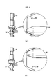
- FIG. 9 is a partial side view of a truing tool for a notch grinding wheel according to an embodiment of the present invention.
- the truing tool T1 comprises a first truer S1 configured to compensate a groove 132' of a notch grinding wheel 132 for grinding a notch of a wafer edge.
- the first truer S1 has an edge of a cross-sectional shape corresponding to a cross-sectional shape of the groove 132' of the notch grinding wheel 132. As shown in FIG. 9 , the edge of the first truer S1 has a trapezoidal cross-sectional shape. Specifically, the edge of the first truer S1 has the same angle as a slanted surface of the groove 132' of the notch grinding wheel 132. A slanted surface of the edge of the first truer S1 is extended such that a thickness of the first truer S1 is larger than a width of the groove 132' of the notch grinding wheel 132.
- the slanted surface of the groove 132' has the same angle as before compensation.
- the thickness of the first truer S1 is larger than the width of the groove 132' to prevent an over-grinding phenomenon that a wafer edge over-rubs against upper and lower slanted surfaces of the groove 132', during wafer edge grinding using the notch grinding wheel 132.
- the first truer S1 is a diamond wheel formed by an electroplating or metal bonding method. That is, the truing tool T1 has a larger hardness than the resin bond groove 132' of the notch grinding wheel 132, and thus can easily compensate the groove 132' of the notch grinding wheel 132.
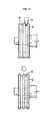
- FIG. 10 is a partial side view of a truing tool for a round grinding wheel according to an embodiment of the present invention.
- the truing tool T2 comprises a second truer S2 configured to compensate a groove 134' of a round grinding wheel 134 for grinding a round of a wafer edge.
- the second truer S2 has an edge of a cross-sectional shape corresponding to a cross-sectional shape of the groove 134' of the round grinding wheel 134. As shown in FIG. 10 , the edge of the second truer S2 has a semicircular cross-sectional shape. Specifically, the edge of the second truer S2 has the same angle and radius of curvature as a groove compensated to meet the shape quality specifications for wafer edge processing using the groove 134' of the round grinding wheel 134. A slanted surface of the edge of the second truer S2 is extended such that a thickness of the second truer S2 is larger than a width of the groove 134' of the round grinding wheel 134.
- the slanted surface of the groove 134' has the same angle as before compensation.
- the thickness of the second truer S2 is larger than the width of the groove 134' to prevent an over-grinding phenomenon that a wafer edge over-rubs against upper and lower surfaces of the groove 134', during wafer edge grinding using the round grinding wheel 134.
- the second truer S2 is a diamond wheel formed by an electroplating or metal bonding method. That is, the truing tool T2 has a larger hardness than the resin bond groove 134' of the round grinding wheel 134, and thus can easily compensate the groove 134' of the round grinding wheel 134.
- the truing tool T2 and the groove 134' of the round grinding wheel 134 compensated by the truing tool T2 should have a shape corresponding to the target quality shape of a wafer edge.
- the truing tool T2 for the round grinding wheel according to the present invention i.e. the second truer S2 contacts the round grinding wheel with a wafer at a predetermined angle, in a different way from a conventional single truer (having the same shape dimension as a wafer and configured to contact a round grinding wheel with a wafer on a level with the wafer).
- a shape dimension of a groove of the round grinding wheel corresponds to those of the conventional single truer and the wafer, but is not the same as those of the conventional single truer and the wafer.
- a shape dimension of a groove of a new typical helical wheel does not correspond to that of a wafer edge. So, before use, the groove of the new helical wheel should be compensated. For this reason, in the case that the second truer of the present invention is manufactured according to a shape dimension of a groove of a conventional helical wheel, a groove of a helical wheel has a shape dimension not corresponding to a target quality shape of a wafer edge.
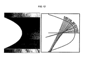
- a method for manufacturing the truing tool T2 for a grinding wheel is described with reference to FIG. 11 .
- the method for manufacturing the truing tool T2 for a grinding wheel according to the present invention includes obtaining a shape dimension of an edge of a second truer through computer simulation, and manufacturing a second truer using the obtained shape dimension.
- a central axis of a cylindrical subject 1 having a shape dimension of a round grinding wheel having no groove is slanted at a predetermined angle on a three-dimensional construction program.
- a groove having a shape of an edge of a completed wafer is constructed on a portion of an outer periphery of the cylindrical subject 1.
- the groove 2 is formed of a wafer edge slanted at a predetermined angle on a portion of an outer periphery of the cylindrical subject 1.
- the three-dimensional construction program is a well-known program such as Auto CAD program or quick express editing program, and its description is herein omitted.
- the cylindrical subject 1 is rotated based on its central axis to expand the slanted groove 2 along the outer periphery of the cylindrical subject 1.
- a groove 3 is formed to extend along the outer periphery of the cylindrical subject 1.
- the shape dimension of the groove 3 extended along the outer periphery of the cylindrical subject 1 is obtained as a shape dimension of an edge of a second truer. That is, the shape dimension of the edge of the second truer can be obtained from radius of curvature and angle of the groove 3. At this time, it is preferable to obtain the shape dimension of the edge of the second truer by extending a slanted surface of the groove 3 along the slanted surface such that thickness of the second truer is larger than width of the groove 3.
- a second truer is manufactured using the obtained shape dimension. It is preferable to manufacture the second truer as a diamond wheel by an electroplating method or a metal bonding method.
- the shape dimension of the edge of the second truer consists of an unlimited number of curves, and thus the shape dimension of the edge of the second truer is impracticable.
- an allowance in design between a theoretical shape and an approximate shape of the second truer is set within a target shape dimension of a wafer edge.
- the second truer is manufactured through the above-mentioned process to have a groove of a round grinding wheel of shape dimension corresponding to a target quality dimension of a wafer edge.
- the first truer S1 may be manufactured in the same way.
- the truing tools T1 and T2 are selectively used to compensate each groove 132' and 134' of the grinding wheels 132 and 134, grooves 132' and 134' can be easily compensated and an over-grinding problem can be solved to increase durability of the grinding wheels 132 and 134.
- the shapes of the grooves 132' and 134' of the grinding wheels 132 and 134 are restored to the original state by the truing tools T1 and T2 of the present invention, thereby solving an unbalanced shape problem in wafer edge processing.
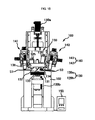
- a wafer edge grinding apparatus 100 includes the truing tools T1 and T2, and compensates and forms the grooves 132' and 134' of the wafer edge grinding wheels 132 and 134. The wafer edge grinding apparatus 100 is described with reference to FIGs. 15 to 17 .
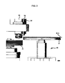
- the grinding apparatus 100 of the present invention includes a chuck 120 for mounting and rotating a wafer (W), a grinding wheel 130 for grinding an edge of the wafer (W), a grinding operation unit 139 for contacting the grooves 132' and 134' of the grinding wheel 130 with the wafer edge, a first truer S1 for compensating the groove 132' of the notch grinding wheel 132, a second truer S2 for compensating the groove 134' of the round grinding wheel 134, and a truing operation unit 140 for moving edges of the first truer S1 and the second truer S2 to contact the edges of the first truer S1 and the second truer S2 with the grooves 132' and 134' of the grinding wheel 130 on a level with the grooves 132' and 134' of the grinding wheel 130, respectively.
- the chuck 120 is a vacuum chuck or an electrostatic chuck for mounting and fixing the wafer (W), and is rotated by a motor 122.
- the grinding wheel 130 includes a round rough-grinding wheel 131, a notch rough-grinding wheel 133, a notch fine-grinding wheel 132 and a round fine-grinding wheel 134.
- the round rough-grinding wheel 131 has a groove (not shown) for rough-grinding a round of a wafer edge
- the notch rough-grinding wheel 133 has a groove (not shown) for rough-grinding a notch of a wafer edge
- the notch fine-grinding wheel 132 has a groove (132' of FIG. 9 ) for fine-grinding a notch of a wafer edge
- the round fine-grinding wheel 134 has a groove (134' of FIG.
- the round fine-grinding wheel 134 is a helical wheel that rotates at a predetermined angle relative to a plane comprising the surface of the wafer (W).
- the notch fine-grinding wheel 132 and the round fine-grinding wheel 134 are rotated by motors 135 and 136, respectively.
- the motors 135 and 136 each is installed and fixed to a wheel head assembly 138 that is installed in a frame 12 of the grinding apparatus 100.
- the round rough-grinding wheel 131 and the notch rough-grinding wheel 133 each is rotated by a motor. That is, the round rough-grinding wheel 131 and the notch rough-grinding wheel 133 are optionally rotated by the motors 135 and 136, and the wheel head assembly 138 having the grinding wheel 130 moves upwards and downwards by the grinding operation unit 139, so that the wheel grooves are contacted with the wafer edge.
- the wheel head assembly 138 has the notch fine-grinding wheel 132, the notch rough-grinding wheel 133 and the round fine-grinding wheel 134 installed therein, and can be moved vertically by the grinding operation unit 139.
- the grinding operation unit 139 includes a first grinding operation unit 139a and a second grinding operation unit 139b.
- the first grinding operation unit 139a operates the wheel head assembly 138 having the notch rough-grinding wheel 133, the notch fine-grinding wheel 132 and the round fine-grinding wheel 134 mounted therein to contact the wafer edge with any one groove of the notch rough-grinding wheel 133, the notch fine-grinding wheel 132 and the round fine-grinding wheel 134.
- the first grinding operation unit 139a is a typical driving means that is moved by rotation of a belt, a pneumatic or hydraulic cylinder, a cam or a gear, for example a servo motor or a hydraulic motor, and is connected to the wheel head assembly 138 and drives the wheel head assembly 138. At this time, the wheel head assembly 138 moves tracing a straight or circular line in a side direction of the wafer edge to contact the wafer edge with the grooves 132' and 134' of the grinding wheel 130.
- the second grinding operation unit 139b mounts and rotates the round rough-grinding wheel 131.
- a control unit 150 may be provided to predict wear of the grooves 132' and 134' of the fine-grinding wheels 132 and 134 from wafer edge processing results and to set the number of times the grooves 132' and 134' are used and a process time.
- the control unit 150 stops the wafer edge grinding and compensates the grooves 132' and 134'.
- the wear of the grooves 132' and 134' is predicted using wafer edge processing results or an optical sensor. Alternatively, the wear of the grooves 132' and 134' may be predicted using the number of times a groove is used or a process time that is arbitrarily set.
- the grooves 132' and 134' of the fine-grinding wheels 132 and 134 it is preferable to compensate the grooves 132' and 134' first. For example, if the groove 134 of the round fine-grinding wheel 134 for grinding the wafer edge is worn, a grinding position is changed to grind the wafer edge by another groove 134' formed on the round fine-grinding wheel 134.
- the grooves 134' formed on the round fine-grinding wheel 134 are worn down, the worn grooves 134' are restored to the original state by the truing tool T2.
- the groove 132' of the notch fine-grinding wheels 132 should be compensated, the groove 132' is compensated by the truing tool T1.
- the truing tools T1 and T2 includes a first truing tool T1 for compensating the groove 132' of the notch fine-grinding wheel 132, and a second truing tool T2 for compensating the groove 134' of the round fine-grinding wheel 134. And, the truing tools T1 and T2 are operated by the truing operation unit 140 installed in the grinding apparatus 100.
- the truing operation unit 140 aligns the edges of the first and second truers S1 and S2 to precisely contact the edges of the first and second truers S1 and S2 with the grooves 132' and 134' of the fine-grinding wheels 132 and 134, and rotates and move the first and second truers S1 and S2 towards the notch fine-grinding wheels 132 and the round fine-grinding wheels 134, respectively.
- the truing operation unit 140 includes a first truing operation unit 141 for operating the first truer S1 to contact the first truer S1 with the groove 132' of the notch fine-grinding wheel 132, and a second truing operation unit 142 for operating the second truer S2 to contact the second truer S2 with the groove 134' of the round fine-grinding wheel 134.
- the first and second truers S1 and S2 are mounted in the first truing operation unit 141 and the second truing operation unit 142 on a level with the groove 132' of the notch fine-grinding wheel 132 and the groove 134' of the round fine-grinding wheels 134, respectively.
- the first and second truers S1 and S2 compensate selectively separately or simultaneously the grooves 132' and 134' of the fine-grinding wheels 132 and 134 by the first and second truing operation units 141 and 142.
- the first and second truing operation units 141 and 142 have the same elements, and only any one truing operation unit is described.
- the second truing operation unit 142 includes a fixing means 145 for mounting the second truer S2, a motor 146 for rotating the second truer S2, a support 147 for fixing the motor 146, and a driving means 148 for moving the support 147.
- the second truer S2 is rotated by the motor 146, and moves to the groove 134' of the round fine-grinding wheel 134 by the driving means 148 and compensates the groove 134' of the round fine-grinding wheel 134.
- the second truing operation unit 142 is different from the first truing operation unit 141 in that the fixing means 145, the motor 146 and the support 147 of the second truing operation unit 142 are slanted at a predetermined angle in the same way as the helical wheel 134.
- a location coordinate of a point where the groove 134' is precisely contacted with the edge of the second truer S2 is stored in the control unit 150, it can reduce the time taken to start a normal grinding operation in a subsequent wafer edge grinding. That is, a coordinate (Y-axis and Z-axis in FIG. 8 ) of a location where the wafer edge is contacted with the grooves 132' and 134' of the grinding wheel 130 and a coordinate (Y-axis in FIG.
- the truing operation unit 140 for operating the truing tools T1 and T2 has a servo motor and an electronic scale for tracking a coordinate of a contact location so that the edges of the truing tools T1 and T2 are contacted with the grooves 132' and 134' of the grinding wheel 130 more precisely.
- the electronic scale and the servo motor are typical components used widely in the field of location and drive control, and detailed description is omitted.
- the grinding wheel 130 is replaced by a new grinding wheel.
- the new grinding wheel can be easily installed using data of the stored location coordinate as mentioned above, and a Y-axis coordinate of a wafer can be found, so that a conventional manual process can be changed to an automatic process.
- FIG. 15 shows the round fine-grinding wheel 134 uses a helical wheel
- the present invention is not limited in this regard.
- the present invention may use a wheel disclosed in the Applicant's Korean Patent Application No. 10-2006-0138709 titled "wheel used for polishing edge part of semiconductor wafer".
- FIG. 18 is a view of a wafer edge grinding apparatus according to another preferred embodiment of the present invention.
- FIG. 19 is an enlarged view of section A of FIG. 18 .
- the grinding apparatus 200 includes a chuck for mounting and rotating a wafer (W), a grinding wheel 230 for grinding an edge of the wafer (W), a grinding operation unit 239 for contacting a groove of the grinding wheel 230 with the wafer edge, a first truer S1 for compensating a groove of a notch fine-grinding wheel 232, a second truer S2' for compensating a groove of a round fine-grinding wheel 234, and a truing operation unit 240 for moving edges of the first truer S1 and the second truer S2' to contact the edges of the first truer S1 and the second truer S2' with the groove of the grinding wheel 230.
- the grinding apparatus 200 of FIGs. 18 and 19 has a similar structure to the grinding apparatus 100 of the above-mentioned embodiment.
- the grinding apparatus 200 of this embodiment is different from the grinding apparatus 100 of the previous embodiment in that the second truer S2' and the first truer S1 are installed in the truing operation unit 240, and a round rough-grinding wheel 231 and the round fine-grinding wheel 234 are mounted parallel with each other on the same rotation axis.
- the grinding wheel 230 includes the round rough-grinding wheel 231, a notch rough-grinding wheel 233, the notch fine-grinding wheel 232 and the round fine-grinding wheel 234.
- the notch rough-grinding wheel 233 and the notch fine-grinding wheel 232 are installed in and fixed to a wheel head assembly 238 of the grinding apparatus 200.
- the round rough-grinding wheel 231 and the round fine-grinding wheel 234 are mounted parallel with each other on the same rotation axis, and more preferably, they are mounted integrally with each other.
- the round fine-grinding wheel 234 is a vertical wheel that is mounted on a level with a plane comprising the surface of the wafer (W) and is rotated.
- the grinding operation unit 239 includes a first grinding operation unit 239a and a second grinding operation unit 239b.
- the first grinding operation unit 239a rotates and moves the wheel head assembly 238 where the notch rough-grinding wheel 233 and the notch fine-grinding wheel 232 are mounted, so that the wafer edge is contacted with any one of grooves of the notch rough-grinding wheel 233 and the notch fine-grinding wheel 232.
- the second grinding operation unit 239b mounts, rotates and moves the round rough-grinding wheel 231 and the round fine-grinding wheel 234 so that the wafer edge is contacted with any one of grooves 231' and 234' of the round rough-grinding wheel 231 and the round fine-grinding wheel 234.
- the round rough-grinding wheel 231 and the round fine-grinding wheel 234 may be mounted parallel with each other or formed integrally with each other in the second grinding operation unit 239b.
- the grinding operation unit 239 is a typical driving means that is moved by rotation of a belt, a pneumatic or hydraulic cylinder, a cam or a gear, for example a servo motor or a hydraulic motor, and the detailed description is omitted.
- the vertical wheel 234 rotated by the second grinding operation unit 239b has four steps. Specifically, the vertical wheel 234 has a first step where a truing groove 235' is formed, a second step and a third step where a groove 231' made of metal bond for rough-grinding a round of the wafer edge is formed, and a fourth step where a groove 234' made of resin bond for fine-grinding a round of the wafer edge is formed.
- the vertical wheel 234 can rough-grind and fine-grind the wafer edge.
- the groove 234' of the fourth step for fine-grinding a round may be compensated or formed by the second truer S2'.
- the first truer S1 and the second truer S2' are mounted parallel with each other on the same rotation axis in the truing operation unit 240.
- the truing operation unit 240 rotates and moves the first truer S1 and the second truer S2' to contact the first truer S1 and the second truer S2' with the groove of the notch fine-grinding wheel 232 and the groove 234' of the round fine-grinding wheel 234, respectively. At this time, the first truer S1 and the second truer S2' are rotated independently or simultaneously by the truing operation unit 240.
- the truing operation unit 240 for operating the first truer S1 and the second truer S2' may have a servo motor and an electronic scale for tracking a location of a contact coordinate so that the edges of the first and second truers S1 and S2' are contacted with the groove of the notch fine-grinding wheel 232 and the groove 234' of the round fine-grinding wheel 234 more precisely.
- this embodiment shows the vertical wheel 234 is used as a round fine-grinding wheel, however the present invention is not limited in this regard.
- the helical wheel (134 of FIG. 15 ) of the previous embodiment may be further installed in the grinding apparatus.
- a second truer (S2 of FIG. 15 ) is further installed to compensate and form a groove of the helical wheel.
- the grooves of the notch fine-grinding wheels 132 and 232 or the grooves of the round fine-grinding wheels 134 and 234 are compensated by the truing tool of the grinding apparatuses 100 and 200.
- the grooves may be compensated by an independent truing apparatus 110 of FIG. 20 .
- the truing apparatus 110 can form grooves in the surfaces of a notch fine-grinding wheel and a round fine-grinding wheel having no groove, in conformity with wafer processing conditions. At this time, substantially the grooves are formed and reformed by a truing tool.
- the truing apparatus 110 includes a first truer S1 and second truers S2 and S2'.
- the first truer S1 and second truers S2 and S2' are equal to the above-mentioned first truer S1 and second truers S2 and S2', and the detailed description is omitted. That is, the truing apparatus 110 rotates and moves the first truer S1 and second truers S2 and S2' to contact the first truer S1 and second truers S2 and S2' with the surface of a grinding wheel so as to form a groove in a notch fine-grinding wheel or a round fine-grinding wheel having no groove.
- the truing apparatus 110 includes a motor 112 for rotating the first truer S1 and second truers S2 and S2', a plate 114 for fixing the motor 112, and a moving means 116 for moving the plate 114.
- the moving means 116 is a servo motor or a hydraulic motor that is moved by rotation of a belt, a pneumatic or hydraulic cylinder, a cam or a gear, and is configured to move the plate 114 to a predetermined location.
- Each element for rotating and moving the first truer S1 and second truers S2 and S2' of the truing apparatus 110 is a typical element, and the detailed description is omitted.
- the truing apparatus 110 including the above-mentioned elements forms grooves in the surfaces of a notch fine-grinding wheel and a round fine-grinding wheel for grinding a wafer edge and compensates the grooves.
- the first truer S1 and the second truer S2' may be mounted parallel with each other on the same rotation axis.
- the truing apparatus 110 manufactures a notch fine-grinding wheel and a round fine-grinding wheel having a groove of the same conditions, keeps them, and when necessary, mounts a selected wheel in the grinding apparatuses 100 and 200. Thus, initial setting time required after a grinding wheel or its groove is replaced can be reduced.
- truing apparatus 110 may be used singularly or in combination with the grinding apparatuses 100 and 200.
- control unit 150 of FIG. 15 and 250 of FIG. 18 each may have a button for manual operation, a storage unit for storing data, and a computer-based basic control system for providing a control signal and power to each operation unit and receiving a signal from a switch and other location/operation/contact signal generating sensor.
- a grinding wheel truing tool its manufacturing method, and a truing apparatus, a method for manufacturing a grinding wheel and a wafer edge grinding apparatus using the same have the following effects.
- the present invention maintains a shape of a groove of a grinding wheel to the original shape to solve a problem involving change in shape of wafer after processing that occurs due to wear unbalance. And, the present invention restores a burned groove resulted from truing, thereby improving durability of a grinding wheel.
- the present invention when compensating a groove, maintains a shape dimension (a radius of curvature of a round and an angle of a slanted surface) of the groove, and thus the present invention eliminates the likelihood that the groove is over-contacted with the edge of a wafer, thereby solving an over-grinding problem.
- the present invention solves an over-grinding problem to improve durability of a grinding wheel.
- the present invention when compensating a groove of a grinding wheel by a truing operation unit, the present invention can identify a Y coordinate of a wafer in advance to reduce an equipment down time spent from truing to normal grinding operation. Thus, the present invention can change a manual compensation of a grinding wheel to an automatic compensation.
- the present invention forms and reforms a groove of the same standard dimension of grinding by use of a truing apparatus capable of utilizing a truing tool, thereby reducing an initial setting time required after a grinding wheel or its groove is replaced by a new one.
- the present invention manufactures a grinding wheel truing tool using a shape dimension of its edge to reduce an equipment down time spent from replacement of a truing tool or a grinding wheel to normal operation.
Landscapes
- Engineering & Computer Science (AREA)
- Mechanical Engineering (AREA)
- Chemical & Material Sciences (AREA)
- Ceramic Engineering (AREA)
- Inorganic Chemistry (AREA)
- Manufacturing & Machinery (AREA)
- Grinding-Machine Dressing And Accessory Apparatuses (AREA)
- Grinding And Polishing Of Tertiary Curved Surfaces And Surfaces With Complex Shapes (AREA)
- Mechanical Treatment Of Semiconductor (AREA)
- Polishing Bodies And Polishing Tools (AREA)
Claims (19)
- Appareil de meulage de bord de rondelle (100) comprenant :un mandrin (120) configuré pour monter et faire tourner une rondelle (W) ;une meule (130, 230) configurée pour meuler un bord de la rondelle (W), et comprenant une meule de dégrossissage (131, 231, 133, 233) et une meule à grain fin (132, 232, 134, 234), chacune ayant une rainure ;une unité de commande de meulage (139, 239) configurée pour monter et faire tourner la meule (130, 230) et déplacer la meule (130, 230) pour faire entrer en contact la rainure de la meule (130, 230) avec le bord de la rondelle (W) montée sur le mandrin (120) ;un outil de dressage de meule (T1, T2) configuré pour compenser la rainure (132', 134', 234') de la meule à grain fin (132, 232, 134, 234) pour meuler finement le bord de la rondelle (W), comprenant un dresseur (S1, S2) ayant un bord du même angle qu'une surface inclinée de la rainure (132', 134', 234') de la meule à grain fin (132, 232, 134, 234) et une forme transversale correspondant à une forme transversale de la rainure (132', 134', 234') ;caractérisé en ce qu'une surface inclinée du bord du dresseur (S1, S2) est étendue de sorte qu'une épaisseur du dresseur (S1, S2) est supérieure à une largeur de la rainure (132', 134', 234') de la meule à grain fin (132, 232, 134, 234).
- Appareil de meulage de bord de rondelle (100) selon la revendication 1,
dans lequel le dresseur (S1) est un premier dresseur (S1) configuré pour compenser une rainure (132') d'une meule à grain fin pour encoche (132, 232) pour meuler finement une encoche du bord de la rondelle (W) et le premier dresseur (S) a un bord de forme trapézoïdale en coupe transversale. - Appareil de meulage de bord de rondelle (100) selon la revendication 1,
dans lequel le dresseur (S2) est un second dresseur (S2) configuré pour compenser une rainure (134', 234') d'une meule à grain fin pour rond (134, 234) pour meuler finement un rond du bord de la rondelle (W), et le second dresseur (S2) a un bord de forme semi-circulaire en coupe transversale. - Appareil de meulage de bord de rondelle (100) selon l'une quelconque des revendications 1 à 3,
dans lequel le dresseur (S1, S2) est une meule diamant formée par galvanoplastie ou contactmétallique. - Procédé pour fabriquer le second dresseur (S2) de l'appareil de meulage de bord rondelle (100) selon la revendication 3, comprenant les étapes consistant à :(a) sur un programme de construction tridimensionnel, former une rainure (2) selon la forme d'un bord d'une rondelle (W) terminée au niveau d'une partie d'une périphérie externe d'un objet cylindrique (1) avec une dimension de forme d'une meule à grain fin pour rond n'ayant pas de rainure, l'objet cylindrique (1) ayant un axe central incliné à un angle prédéterminé ;(b) par le biais de la simulation informatique, faire tourner l'objet cylindrique (1) en fonction de l'axe central pour expanser la rainure (2) en forme de bord de rondelle le long de la périphérie externe de l'objet cylindrique (1) ;(c) obtenir une dimension de forme de la rainure expansée (3) en tant que dimension de forme d'un bord du second dresseur (S2) ; et(d) fabriquer le second dresseur (S2) en utilisant la dimension de forme obtenue.
- Procédé pour fabriquer le second dresseur (S2) selon la revendication 5, dans lequel, à l'étape (c), la dimension de forme du bord du second dresseur (S2) est obtenue en étendant une surface inclinée de la rainure expansée (3) le long de la surface inclinée de sorte qu'une épaisseur du second dresseur (S2) est supérieure à une largeur de la rainure (3).
- Procédé pour fabriquer une meule de bord de rondelle, qui fabrique une meule à grain fin (132, 232, 134, 234) en formant une rainure (132', 134', 234') le long d'une périphérie externe de la meule à grain fin n'ayant pas de rainure, utilisant le dresseur (S1, S2) de l'appareil de meulage de bord de rondelle (100) selon l'une quelconque des revendications 1 à 4.
- Appareil de meulage de bord de rondelle (100) selon la revendication 1, dans lequel :la meule de dégrossissage (131, 231, 133, 233) comprend une meule de dégrossissage pour rond (131, 231) et une meule de dégrossissage pour encoche (133, 233), chacune ayant une rainure ;lameule à grain fin (131, 231, 133, 233) comprend une meule à grain fin pour encoche (132, 232) et une meule à grain fin pour rond (134, 234), ayant chacune une rainure ;le dresseur (S1, S2) comprend un premier dresseur (S1) ayant un bord d'une forme transversale correspondant à une forme transversale de la rainure (132') de la meule à grain fin pour encoche (132, 232) et configuré pour compenser la rainure (132') de la meule à grain fin pour encoche (132, 232) ;le dresseur (S1, S2) comprend un second dresseur (S2) ayant un bord d'une forme transversale correspondant à une forme transversale de la rainure (134', 234') de la meule à grain fin pour rond (134, 234) et configuré pour compenser la rainure (134', 234') de la meule à grain fin pour rond (134, 234) ; etune unité de commande de dressage (140, 240) configurée pour monter et faire tourner les premier et second dresseurs (S1, S2) et déplacer les premier et second dresseurs (S1, S2) pour faire entrer en contact les bords des premier et second dresseurs (S1, S2) avec la rainure de chaque meule au même niveauque la rainure de chaque meule,dans lequel une surface inclinée du bord du premier dresseur (S1) est étendue de sorte qu'une épaisseur du premier dresseur (S1) est supérieure à une largeur de la rainure (132') de la meule à grain fin pour encoche (132, 232), etdans lequel une surface inclinée du bord du second dresseur (S2) est étendue de sorte qu'une épaisseur du second dresseur (S2) est supérieure à une largeur de la rainure (134', 234') de la meule à grain fin pour rond (134, 234).
- Appareil de meulage de bord de rondelle (100) selon la revendication 8, dans lequel chacun parmi le premier dresseur (S1) et le second dresseur (S2) est une meule diamant formée par galvanoplastie oucontactmétallique.
- Appareil de meulage de bord de rondelle (100) selon la revendication 8, comprenant en outre :une unité de commande (150, 250) configurée pour prévoir l'usure de la rainure de la meule (130, 230) à partir des résultats de procédé de bord de rondelle, déterminer le nombre de fois que la rainure est utilisée et un temps de traitement, et dans le cas dans lequel l'usure de la rainure est prévue d'après les résultats de traitement de bord de rondelle ou que le nombre de fois que la rainure est utilisée atteint un nombre prédéterminé ou que le temps de traitement dépasse un temps prévu, arrêter le meulage du bord de rondelle.
- Appareil de meulage de bord de rondelle (100) selon la revendication 10, dans lequel, en réponse à l'arrêt de meulage de bord de rondelle, l'unité de commande (150, 250) commande l'unité de commande de dressage (140, 240) pour faire entrer en contact le premier dresseur (S1) ou le second dresseur (S2) avec la meule à grain fin pour encoche (132, 232) ou la meule à grain fin pour rond (134, 234), respectivement, afin de compenser la rainure de la meule à grain fin (130, 230) ou commande l'unité de commande de meulage (139, 239) pour faire entrer en contact le bord de rondelle avec une rainure (132') de la meule à grain fin pour encoche (132, 232) qui n'est pas usée ou une rainure (134', 234') de la meule à grain fin pour rond (134, 234) qui n'est pas usée.
- Appareil de meulage de bord de rondelle (100) selon la revendication 8, dans lequel la meule à grain fin pour rond (134) est une meule hélicoïdale qui est inclinée à un angle prédéterminé et est entraînée en rotation par rapport à un plan comprenant une surface de la rondelle (W).
- Appareil de meulage de bord de rondelle (100) selon la revendication 12,
dans lequel l'unité de commande de dressage (140) comprend :une première unité de commande de dressage (141) configurée pour monter le premier dresseur (S1) au niveau de la rainure (132') de la meule à grain fin pour encoche (132, 232) et tourner et déplacer le premier dresseur (S1) pour mettre en contact le premier dresseur (S1) avec la rainure (132') de la meule à grain fin pour encoche (132, 232) ; etune seconde unité de commande de dressage (142) configurée pour monter le second dresseur (S2) au niveau dela rainure (134', 234') de la meule à grain fin pour rond (134, 234) et faire tourner et déplacer le second dresseur (S2) pour mettre en contact le second dresseur (S2) avec la rainure (134', 234') de la meule à grain fin pour rond (134, 234). - Appareil de meulage de bord de rondelle (100) selon la revendication 12,
dans lequel l'unité de commande de meulage (139) comprend :une première unité de commande de meulage (139a) configurée pour monter et faire tourner la meule de dégrossissage pour encoche (133), la meule à grain fin pour encoche (132) et la meule à grain fin pour rond (134) ; etune seconde unité de commande de meulage (139b) configurée pour monter et faire tourner la meule de dégrossissage pour rond (131). - Appareil de meulage de bord de rondelle (100) selon la revendication 8,
dans lequel la meule à grain fin pour rond (234) est une meule verticale qui est montée au niveau d'un plan comprenant une surface de la rondelle (W) et est entraînée en rotation. - Appareil de meulage de bord de rondelle (100) selon la revendication 15,
dans lequel le premier dresseur (S1) et le second dresseur (S2') sont montés parallèlement entre eux, sur le même axe de rotation dans l'unité de commande de dressage (240). - Appareil de meulage de bord de rondelle (100) selon la revendication 15,
dans lequel l'unité de commande de meulage (239) comprend :une première unité de commande de meulage (239a) configurée pour monter et faire tourner la meule de dégrossissage pour encoche (233) et la meule à grain fin pour encoche (232) ; etune seconde unité de commande de meulage (239b) configurée pour monter et faire tourner la meule de dégrossissage pour rond (231) et la meule à grain fin pour rond (234). - Appareil de meulage de bord de rondelle (100) selon la revendication 17,
dans lequel la meule de dégrossissage pour rond (231) et la meule à grain fin pour rond (234) sont montées parallèlement entre elles sur le même axe de rotation dans la seconde unité de commande de meulage (239b). - Appareil de meulage de bord de rondelle (100) selon la revendication 15,
dans lequel la meule de dégrossissage pour rond (231) et la meule à grain fin pour rond (234) sont formées de manière solidaire l'une par rapport à l'autre.
Applications Claiming Priority (1)
| Application Number | Priority Date | Filing Date | Title |
|---|---|---|---|
| KR1020070131306A KR20090063804A (ko) | 2007-12-14 | 2007-12-14 | 연삭 휠 트루잉 공구 및 그 제작방법, 이를 이용한 트루잉장치, 연삭 휠의 제작방법, 및 웨이퍼 에지 연삭장치 |
Publications (3)
| Publication Number | Publication Date |
|---|---|
| EP2070652A2 EP2070652A2 (fr) | 2009-06-17 |
| EP2070652A3 EP2070652A3 (fr) | 2011-10-05 |
| EP2070652B1 true EP2070652B1 (fr) | 2013-06-19 |
Family
ID=40427936
Family Applications (1)
| Application Number | Title | Priority Date | Filing Date |
|---|---|---|---|
| EP08021666.6A Active EP2070652B1 (fr) | 2007-12-14 | 2008-12-12 | Appareil de meulage des bords de rondelles utilisant un outil de dressage de meule et son procédé de fabrication, et procédé de fabrication de meule |
Country Status (5)
| Country | Link |
|---|---|
| US (2) | US8398464B2 (fr) |
| EP (1) | EP2070652B1 (fr) |
| JP (1) | JP5416956B2 (fr) |
| KR (1) | KR20090063804A (fr) |
| CN (1) | CN101456160B (fr) |
Families Citing this family (35)
| Publication number | Priority date | Publication date | Assignee | Title |
|---|---|---|---|---|
| SE532460C2 (sv) * | 2006-07-11 | 2010-01-26 | Tj Utveckling Ab | Svarvverktyg för en slipsten |
| TW201223699A (en) * | 2010-09-03 | 2012-06-16 | Saint Gobain Abrasives Inc | Bonded abrasive articles, method of forming such articles, and grinding performance of such articles |
| TWI544064B (zh) | 2010-09-03 | 2016-08-01 | 聖高拜磨料有限公司 | 粘結的磨料物品及形成方法 |
| CN102092009B (zh) * | 2010-12-10 | 2012-09-05 | 天津大学 | 陶瓷结合剂金刚石修整轮 |
| JP2012169024A (ja) * | 2011-02-16 | 2012-09-06 | Showa Denko Kk | 磁気記録媒体用ガラス基板の製造方法 |
| KR101400876B1 (ko) * | 2012-05-29 | 2014-06-02 | 영남대학교 산학협력단 | 서피스 텍스쳐링을 위한 연삭 장치 및 방법 |
| CN104703758A (zh) * | 2012-10-10 | 2015-06-10 | 旭硝子株式会社 | 弹性砂轮的修整方法 |
| US9718164B2 (en) | 2012-12-06 | 2017-08-01 | Taiwan Semiconductor Manufacturing Company, Ltd. | Polishing system and polishing method |
| WO2014106157A1 (fr) | 2012-12-31 | 2014-07-03 | Saint-Gobain Abrasives, Inc. | Article abrasif lié et procédé d'abrasion |
| WO2014106156A1 (fr) | 2012-12-31 | 2014-07-03 | Saint-Gobain Abrasives, Inc. | Article abrasif lié et procédé de broyage |
| US9102039B2 (en) | 2012-12-31 | 2015-08-11 | Saint-Gobain Abrasives, Inc. | Bonded abrasive article and method of grinding |
| JP6071611B2 (ja) * | 2013-02-13 | 2017-02-01 | Mipox株式会社 | オリエンテーションフラット等切り欠き部を有する、結晶材料から成るウエハの周縁を、研磨テープを使用して研磨することにより円形ウエハを製造する方法 |
| US9833877B2 (en) | 2013-03-31 | 2017-12-05 | Saint-Gobain Abrasives, Inc. | Bonded abrasive article and method of grinding |
| US9254549B2 (en) * | 2013-05-07 | 2016-02-09 | Jtekt Corporation | Grinding machine |
| JP6204848B2 (ja) * | 2014-02-17 | 2017-09-27 | 株式会社荏原製作所 | 研磨装置および研磨方法 |
| JP6315579B2 (ja) | 2014-07-28 | 2018-04-25 | 昭和電工株式会社 | SiCエピタキシャルウェハの製造方法 |
| JP6609847B2 (ja) * | 2014-08-06 | 2019-11-27 | 日本電気硝子株式会社 | 板状物の端面加工装置 |
| CN110450009B (zh) * | 2014-12-31 | 2021-08-13 | Hoya株式会社 | 基板的制造方法、基板端面的加工装置、基板端面的加工方法和磨削用磨石 |
| CN106141920B (zh) * | 2016-07-14 | 2018-04-17 | 厦门大学 | 一种成形磨砂轮开槽机构及方法 |
| KR102803725B1 (ko) * | 2016-09-30 | 2025-05-07 | 엘지디스플레이 주식회사 | 기판 가공 장치 및 이를 이용한 표시장치 |
| CN107553356B (zh) * | 2017-10-23 | 2024-03-15 | 长沙长泰机器人有限公司 | 一种金刚石砂轮 |
| CN109048024B (zh) * | 2018-08-31 | 2021-09-24 | 华域汽车车身零件(上海)有限公司 | 一种焊接电极帽的修磨方法 |
| CN109623553A (zh) * | 2018-12-25 | 2019-04-16 | 西安奕斯伟硅片技术有限公司 | 一种倒角磨轮、倒角研磨装置及研磨方法 |
| CN110605629B (zh) * | 2019-09-19 | 2022-11-18 | 西安奕斯伟材料科技有限公司 | 一种研磨装置 |
| KR102855980B1 (ko) * | 2020-04-09 | 2025-09-05 | 삼성전자주식회사 | 웨이퍼 트리밍 장치 |
| JP7567454B2 (ja) * | 2020-12-24 | 2024-10-16 | 住友金属鉱山株式会社 | 圧電性酸化物単結晶ウエハのエッジポリッシュ方法および圧電性酸化物単結晶ウエハの製造方法 |
| JP7093875B2 (ja) * | 2021-06-24 | 2022-06-30 | 一郎 片山 | ワーク加工装置、砥石、およびワーク加工方法 |
| CN114150286A (zh) * | 2021-08-18 | 2022-03-08 | 重庆佳禾光电科技有限公司 | 一种镀膜监控片及其制备方法 |
| JP7696865B2 (ja) * | 2022-06-22 | 2025-06-23 | 株式会社東京精密 | ツルアー成形方法 |
| CN115502817B (zh) * | 2022-10-01 | 2023-10-31 | 江苏金正阳矿业有限公司 | 一种大理石板材加工的自动磨边设备与方法 |
| CN118990277B (zh) * | 2024-10-24 | 2025-03-04 | 河南铭义新材料科技股份有限公司 | 一种高速砂轮生产用打磨装置 |
| CN119260605A (zh) * | 2024-11-22 | 2025-01-07 | 西安奕斯伟材料科技股份有限公司 | 硅片倒角砂轮修整系统和硅片 |
| CN119427122A (zh) * | 2024-11-29 | 2025-02-14 | 西安奕斯伟材料科技股份有限公司 | 磨轮、晶圆磨削装置及晶圆磨削方法 |
| CN119458050A (zh) * | 2024-12-18 | 2025-02-18 | 西安奕斯伟材料科技股份有限公司 | 一种硅片边缘研磨设备、方法及装置 |
| CN121061760B (zh) * | 2025-11-05 | 2026-02-17 | 洛阳九久耐磨材料制造有限公司 | 一种金刚石砂轮修整方法及系统 |
Family Cites Families (14)
| Publication number | Priority date | Publication date | Assignee | Title |
|---|---|---|---|---|
| US4457113A (en) | 1982-02-24 | 1984-07-03 | Super-Cut, Inc. | Protected super-abrasive grinding tool |
| JP2639811B2 (ja) * | 1987-11-02 | 1997-08-13 | 株式会社ディスコ | ブレード刃先の放電形成方法 |
| JP2584104B2 (ja) * | 1990-05-31 | 1997-02-19 | オークマ株式会社 | 砥石形状定義装置 |
| JPH05269666A (ja) * | 1992-03-25 | 1993-10-19 | Toyoda Mach Works Ltd | 砥石の修正方法 |
| ATE246072T1 (de) | 1996-06-15 | 2003-08-15 | Unova Uk Ltd | Flexible verbindung einer schleifmaschinenspindel zu einer plattform |
| US6123605A (en) * | 1997-02-20 | 2000-09-26 | Koyo Machine Industries Company Ltd. | Dressing device for centerless grinding machine and dressing method for centerless grinding machine |
| JPH11320364A (ja) * | 1998-05-19 | 1999-11-24 | Shin Etsu Handotai Co Ltd | ウエーハの面取り部の軟研削加工管理方法及び面取り装置 |
| JPH11333717A (ja) * | 1998-05-29 | 1999-12-07 | Sony Corp | 研削砥石の成形装置及びその使用方法 |
| JP2000084852A (ja) * | 1998-09-07 | 2000-03-28 | Nippon Seiko Kk | 研削盤用ドレス装置 |
| GB0002251D0 (en) * | 2000-02-02 | 2000-03-22 | Unova Uk Ltd | Improvements in and relating to grinding machines |
| JP4441823B2 (ja) * | 2003-11-26 | 2010-03-31 | 株式会社東京精密 | 面取り砥石のツルーイング方法及び面取り装置 |
| JP2007044817A (ja) * | 2005-08-10 | 2007-02-22 | Tokyo Seimitsu Co Ltd | ウェーハ面取り装置、ウェーハ面取り用砥石、及びツルーイング砥石 |
| JP4742845B2 (ja) * | 2005-12-15 | 2011-08-10 | 信越半導体株式会社 | 半導体ウエーハの面取り部の加工方法及び砥石の溝形状の修正方法 |
| KR100866421B1 (ko) | 2006-12-29 | 2008-10-31 | 주식회사 실트론 | 반도체 웨이퍼 엣지 연마 휠 |
-
2007
- 2007-12-14 KR KR1020070131306A patent/KR20090063804A/ko not_active Ceased
-
2008
- 2008-12-09 JP JP2008313442A patent/JP5416956B2/ja active Active
- 2008-12-10 US US12/332,136 patent/US8398464B2/en active Active
- 2008-12-12 CN CN200810188110XA patent/CN101456160B/zh active Active
- 2008-12-12 EP EP08021666.6A patent/EP2070652B1/fr active Active
-
2012
- 2012-04-09 US US13/442,584 patent/US9211631B2/en active Active
Also Published As
| Publication number | Publication date |
|---|---|
| EP2070652A2 (fr) | 2009-06-17 |
| CN101456160B (zh) | 2013-11-06 |
| EP2070652A3 (fr) | 2011-10-05 |
| US20090156104A1 (en) | 2009-06-18 |
| KR20090063804A (ko) | 2009-06-18 |
| JP5416956B2 (ja) | 2014-02-12 |
| US8398464B2 (en) | 2013-03-19 |
| US20120233930A1 (en) | 2012-09-20 |
| CN101456160A (zh) | 2009-06-17 |
| JP2009142979A (ja) | 2009-07-02 |
| US9211631B2 (en) | 2015-12-15 |
Similar Documents
| Publication | Publication Date | Title |
|---|---|---|
| EP2070652B1 (fr) | Appareil de meulage des bords de rondelles utilisant un outil de dressage de meule et son procédé de fabrication, et procédé de fabrication de meule | |
| JP4441823B2 (ja) | 面取り砥石のツルーイング方法及び面取り装置 | |
| JP4874121B2 (ja) | 砥石車 | |
| US6336842B1 (en) | Rotary machining apparatus | |
| WO2000063963A1 (fr) | Conditionnement non-abrasif de tampons de polissage | |
| CN101486167A (zh) | 通过转动的修整工具修整加工轮的装置和方法以及具有这种装置的加工工具 | |
| JP2016203342A (ja) | ツルーアーの製造方法および半導体ウェーハの製造方法、ならびに半導体ウェーハの面取り加工装置 | |
| JPH09168953A (ja) | 半導体ウェーハのエッジ研摩方法及び装置 | |
| JP2009078326A (ja) | ウェーハ面取り装置、及びウェーハ面取り方法 | |
| JP5206194B2 (ja) | 砥石のツルーイング方法およびツルーイング装置 | |
| CN112454161B (zh) | 研削装置及研削方法 | |
| JP2007030119A (ja) | ウェーハ面取り装置及びウェーハ面取り方法 | |
| JP7158702B2 (ja) | 面取り研削装置 | |
| JP2003103460A (ja) | 工作物表面を油溜りがある超仕上面に研削加工する方法及び装置 | |
| US7137866B2 (en) | Polishing apparatus and method for producing semiconductors using the apparatus | |
| JP2007061978A (ja) | ウェーハ面取り砥石のツルーイング方法及びウェーハ面取り装置 | |
| CN108161744A (zh) | 一种抛光工具修整系统及其修整方法 | |
| CN1855380A (zh) | 一种化学机械抛光机 | |
| US7166013B2 (en) | Polishing apparatus and method for producing semiconductors using the apparatus | |
| KR20170087300A (ko) | 에지 그라인딩 장치 | |
| JP2010094758A (ja) | 情報記録媒体用ガラス基板の製造方法およびその製造装置 | |
| JP2003136385A (ja) | 端面加工方法および装置 | |
| JP2004330345A (ja) | 薄片ワークの研削加工法およびその装置 | |
| JP2008168402A (ja) | 光学素子の研削装置及び研削方法 | |
| JP2003103462A (ja) | 2個の砥石台を有する研削盤におけるツルーイング装置 |
Legal Events
| Date | Code | Title | Description |
|---|---|---|---|
| PUAI | Public reference made under article 153(3) epc to a published international application that has entered the european phase |
Free format text: ORIGINAL CODE: 0009012 |
|
| AK | Designated contracting states |
Kind code of ref document: A2 Designated state(s): AT BE BG CH CY CZ DE DK EE ES FI FR GB GR HR HU IE IS IT LI LT LU LV MC MT NL NO PL PT RO SE SI SK TR |
|
| AX | Request for extension of the european patent |
Extension state: AL BA MK RS |
|
| RIN1 | Information on inventor provided before grant (corrected) |
Inventor name: HYUN, DONG-HWAN Inventor name: KIM, JAE-YOUNG Inventor name: YONG, MUN-SUK Inventor name: KIM, YONG-DUG Inventor name: JUNG, HWAN-YUN Inventor name: LEE, KYUNG-MOO Inventor name: CHO, GYE-JE |
|
| PUAL | Search report despatched |
Free format text: ORIGINAL CODE: 0009013 |
|
| AK | Designated contracting states |
Kind code of ref document: A3 Designated state(s): AT BE BG CH CY CZ DE DK EE ES FI FR GB GR HR HU IE IS IT LI LT LU LV MC MT NL NO PL PT RO SE SI SK TR |
|
| AX | Request for extension of the european patent |
Extension state: AL BA MK RS |
|
| RIC1 | Information provided on ipc code assigned before grant |
Ipc: B24D 18/00 20060101ALI20110829BHEP Ipc: B24B 53/07 20060101AFI20110829BHEP Ipc: B24B 9/06 20060101ALI20110829BHEP |
|
| 17P | Request for examination filed |
Effective date: 20120320 |
|
| AKX | Designation fees paid |
Designated state(s): DE FR |
|
| 17Q | First examination report despatched |
Effective date: 20120627 |
|
| GRAP | Despatch of communication of intention to grant a patent |
Free format text: ORIGINAL CODE: EPIDOSNIGR1 |
|
| GRAS | Grant fee paid |
Free format text: ORIGINAL CODE: EPIDOSNIGR3 |
|
| GRAA | (expected) grant |
Free format text: ORIGINAL CODE: 0009210 |
|
| AK | Designated contracting states |
Kind code of ref document: B1 Designated state(s): DE FR |
|
| REG | Reference to a national code |
Ref country code: DE Ref legal event code: R096 Ref document number: 602008025373 Country of ref document: DE Effective date: 20130814 |
|
| PLBE | No opposition filed within time limit |
Free format text: ORIGINAL CODE: 0009261 |
|
| STAA | Information on the status of an ep patent application or granted ep patent |
Free format text: STATUS: NO OPPOSITION FILED WITHIN TIME LIMIT |
|
| 26N | No opposition filed |
Effective date: 20140320 |
|
| REG | Reference to a national code |
Ref country code: DE Ref legal event code: R097 Ref document number: 602008025373 Country of ref document: DE Effective date: 20140320 |
|
| REG | Reference to a national code |
Ref country code: FR Ref legal event code: ST Effective date: 20140829 |
|
| PG25 | Lapsed in a contracting state [announced via postgrant information from national office to epo] |
Ref country code: FR Free format text: LAPSE BECAUSE OF NON-PAYMENT OF DUE FEES Effective date: 20131231 |
|
| PGFP | Annual fee paid to national office [announced via postgrant information from national office to epo] |
Ref country code: DE Payment date: 20250922 Year of fee payment: 18 |