EP2070842A2 - Support d'outil, en forme de récipient plastique - Google Patents
Support d'outil, en forme de récipient plastique Download PDFInfo
- Publication number
- EP2070842A2 EP2070842A2 EP08018114A EP08018114A EP2070842A2 EP 2070842 A2 EP2070842 A2 EP 2070842A2 EP 08018114 A EP08018114 A EP 08018114A EP 08018114 A EP08018114 A EP 08018114A EP 2070842 A2 EP2070842 A2 EP 2070842A2
- Authority
- EP
- European Patent Office
- Prior art keywords
- insert
- base plate
- workpiece carrier
- container
- centering
- Prior art date
- Legal status (The legal status is an assumption and is not a legal conclusion. Google has not performed a legal analysis and makes no representation as to the accuracy of the status listed.)
- Granted
Links
Images




Classifications
-
- B—PERFORMING OPERATIONS; TRANSPORTING
- B65—CONVEYING; PACKING; STORING; HANDLING THIN OR FILAMENTARY MATERIAL
- B65D—CONTAINERS FOR STORAGE OR TRANSPORT OF ARTICLES OR MATERIALS, e.g. BAGS, BARRELS, BOTTLES, BOXES, CANS, CARTONS, CRATES, DRUMS, JARS, TANKS, HOPPERS, FORWARDING CONTAINERS; ACCESSORIES, CLOSURES, OR FITTINGS THEREFOR; PACKAGING ELEMENTS; PACKAGES
- B65D85/00—Containers, packaging elements or packages, specially adapted for particular articles or materials
- B65D85/68—Containers, packaging elements or packages, specially adapted for particular articles or materials for machines, engines or vehicles in assembled or dismantled form
-
- B—PERFORMING OPERATIONS; TRANSPORTING
- B65—CONVEYING; PACKING; STORING; HANDLING THIN OR FILAMENTARY MATERIAL
- B65D—CONTAINERS FOR STORAGE OR TRANSPORT OF ARTICLES OR MATERIALS, e.g. BAGS, BARRELS, BOTTLES, BOXES, CANS, CARTONS, CRATES, DRUMS, JARS, TANKS, HOPPERS, FORWARDING CONTAINERS; ACCESSORIES, CLOSURES, OR FITTINGS THEREFOR; PACKAGING ELEMENTS; PACKAGES
- B65D2585/00—Containers, packaging elements or packages specially adapted for particular articles or materials
- B65D2585/68—Containers, packaging elements or packages specially adapted for particular articles or materials for machines, engines, or vehicles in assembled or dismantled form
- B65D2585/6802—Containers, packaging elements or packages specially adapted for particular articles or materials for machines, engines, or vehicles in assembled or dismantled form specific machines, engines or vehicles
- B65D2585/6875—Containers, packaging elements or packages specially adapted for particular articles or materials for machines, engines, or vehicles in assembled or dismantled form specific machines, engines or vehicles engines, motors, machines and vehicle parts
Definitions
- the invention relates to a workpiece carrier, designed as a plastic container, in particular made in one piece by injection molding, which has a separate insert with Werk Braunhaltemittein for receiving workpieces, is provided with internal locking means and wherein the insert with the locking means anchoring counter-locking means.
- a reusable package in the form of a container having on a common base primary fasteners receiving complementary secondary fasteners.
- the secondary fastening means are provided with positioning elements which are adapted to the shape of the products to be packaged. When changing or changing the products to be packaged, it is necessary to exchange or adjust the positioning elements.
- a container for receiving solar cells has become known.
- a solar cell receiving insert is introduced, which is latched to the container.
- For larger solar cells is intended to store them without use in the container.
- the solar cells are stacked in the container.
- DE 36 30 566 C2 or the DE 37 03 317 A1 are for the internal transport of workpieces or assembly parts as well as for the transport of these parts from the manufacturing plant to the assembly plant and the feeder From workpiece to automatically loaded assembly machines serving workpiece carrier has become known.
- the stored workpieces are in this case by projections and / or depressions, ie recorded by mold cavities, which allows both automated handling and safe transport, in which the individual workpieces should not touch.
- This known workpiece carrier is made of two plastic parts and consists of a frame and a plate provided with the mold cavities (openings and / or depressions and / or projections).
- the deep-drawn or injection-molded plastic sheet is thereby slipped over the frame and thus simultaneously increases the stability of the workpiece carrier.
- the invention is therefore an object of the invention to provide a generic workpiece carrier without the disadvantages mentioned above, which in particular provides a much higher stability with simple production and enables a positionally safe storage of particular alsstülpbaren or auffädelbaren workpieces.
- the insert consists of a base plate, which is provided on its inner bottom surface with parallel spaced apart centering sleeves, the centering sleeves have a conically tapered inlet bevel and spaced between them Centering sleeves are formed across the width of the base plate extending support elements.
- the preferably immediately with injection-molded centering provide a secure fit of obviouslystülpten or threaded on its outer circumference workpieces, such as planetary gears, both during transport and during storage.
- the conical insertion bevel formed at the upper, free end of the centering sleeves facilitates the insertion or threading of the workpieces.
- an advantageous embodiment of the invention provides that the support elements are formed with parallel spaced-apart, vertical ribs, which are each assigned in pairs a centering sleeve as anti-rotation for readilylagernde workpieces.
- workpieces threaded onto the centering sleeves and having, on their outer circumference, cutouts which correspond in their width to the outer dimensions of a respective pair of webs can be positioned securely without the possibility of movement.
- support elements supporting ribs are provided, which are formed in the transition region between the support elements and the base plate of the insert orthogonal to the support elements.
- an insert according to the invention consists of a base plate, on whose side edges in each case an integrally formed from the inner surface of the base plate in the vertical direction spacer profile is formed, wherein the insert with the spacer profiles can be inserted leading into the container. Thereby, that the insert with the spacer profiles is inserted into the container in advance, the profiles find contact with the tank bottom.
- the base plate is thus supported, wherein the outer bottom surface of the base plate terminates approximately flush with the upper edge of the container.
- the spacer profiles at their free ends in each case a top plate, which is formed on its surface with locking means of the container bottom complementary centering.
- the centering segments respectively engage or engage according to their distributed arrangement in grooves of a centering cross, preferably in the container bottom, whereby the insert is centered and locked horizontally in a manner secure against movement.
- the invention provides that protrude at two opposite distance profiles, the top plates on the side edge of the base plate, wherein the protruding into the slot-shaped locking openings of the container walls can be latched.
- the insert may be formed on the inner surface of its base plate with parallel spaced guide sleeves.
- the guide sleeves can advantageously be assigned across the width of the base plate extending and preferably formed with ribs for preventing rotation support elements.
- An embodiment of the invention provides that the base plate of the insert on its final with the container upper edge outer surface with a plurality of circumferentially distributed around the openings of the guide sleeves arranged centering holes is trained. It can thus be stored workpieces that have, for example, a shaft and an educated, large-scale form or headboard. After insertion of the shaft in the guide sleeve, the area compared to the guide sleeve opening significantly larger molding is thus on the outer bottom surface adjacent to the guide sleeve opening of the insert base plate. In this area formed on the underside of the workpiece centering cams can engage in the centering holes, whereby an unintentional rotational or pivotal movement of the workpiece is effectively prevented.
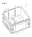
- FIG. 1 illustrated workpiece carrier 1 in rectangular container design is made in one piece by injection molding of plastic and has a closed bottom 2 and longitudinal walls 3 and end walls 4.
- a Zentriernutennch 7 result (see Fig. 2 ).
- the inner surfaces 8 of the end walls 4 are provided on the one hand with horizontal, stepped spaced apart locking webs 9 and on the other hand formed at their bottom ends 10 with slot-shaped locking openings 11.
- latchable inserts are provided in the workpiece carrier.
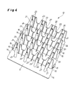
- One in the 4 to 6 illustrated insert 12 has for this purpose a base plate 13 which is formed on its the end walls 4 of the workpiece carrier 1 facing side edges 14 with angled locking tabs 15 which are provided at their free ends with over the side edges 14 economicallyorkragenden ribs 16. Furthermore, the base plate 13 on its the Zentriernutenish 7 of the container bottom 2 facing outer surface 17 with complementary to the centering grooves 7 projections 18 (see. Fig. 6 ), which are arranged distributed locally.
- the projections 18 engage in the centering 6 and the Zentriernutennch 7 and position so horizontally safe movement, the insert 12 on the container bottom 2.
- the ribs 16 of the locking tabs 15 engage with the locking webs 9 of the workpiece carrier. 1 , whereby the insert 12 is held vertically secure in the workpiece carrier 1.
- the stepped arrangement of the locking webs 9 on the end walls 4 in this case allows a variable locking height of the insert 12th
- a plurality of centering sleeves 21 are formed on the inner surface 20 of the base plate 13 in rows. At the upper, free end of the centering sleeves 21 are provided with a conical insertion bevel 22, which allows easy threading of the workpieces 19.
- the insert 12 is formed with a plurality of support elements 23 which are injection-molded on their inner surface 20 and extend from the side edge 14 to the side edge 14 across the base plate 13.
- the support members 23 are provided with vertical ribs 24, wherein each one of two such ribs 24 formed Rib pair 25 is associated with the workpieces 19 as rotation.
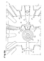
- the pair of ribs 25 engages in a complementary to its overall width recess 26 on the outer circumference of the workpiece 19, whereby a positionally correct position of the workpieces 19 is achieved in the insert 12 (see Fig. 5a ).
- Fig. 5b is a reduced in diameter relative to the workpiece 19 workpiece 19a shown, which has on its outer periphery a complementary to the inner dimension of the pair of ribs 25 projection 44.
- the projection 44 engages between the ribs 24 of a pair of ribs 25, whereby the workpiece 19a is guided and positioned in the correct position and secured against rotation.
- additional support ribs 27 are molded onto the support elements 23, preferably upwardly wedge-shaped.
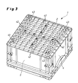
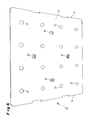
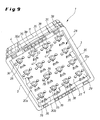
- a in the embodiment of the Fig. 7 to 9 illustrated insert 28 has a base plate 29, at the side edges 30a, b, c, d each one of the inner surface 31 in the vertical direction downwardly extending spacer profile 32a, b, c, d is formed.
- each one of the inner surface 31 in the vertical direction downwardly extending spacer profile 32a, b, c, d is formed.
- on the inner surface 31 of the base plate 29 in the installed position in the workpiece carrier projecting guide sleeves 35 molded.
- the spacer profiles 32a, b, c, d are provided at their upper end with top plates 33a, b, c, d, on the surface thereof with centering elements 34 complementary to the depressions 6 or the centering cross 7 of the container bottom 2.
- the top plates 33b and 33d of the spacer profiles 32b and 32d project beyond the side edges 30b and 30d of the base plate 29 and engage in the slot-shaped detent openings after insertion of the insert 28, which is inserted in advance with the spacer profiles 32a, b, c, d 11 of the workpiece carrier 1 a.
- the centering elements 34 integrally formed on the top plates 33a, b, c, d engage in the grooves of the centering cross 7 and fix the insert 28 in a manner secure against movement on the container bottom 2.
- the top plates 33a and 33c are formed with protruding ends for latching engagement in the slot-shaped latching openings 11.
- Such a workpiece is inserted from the outer surface 37 of the base plate 29 forth with the shaft or the like pin in the cavity or the cylindrical opening of the guide sleeve 35 and thus received and held by the guide sleeve 35.
- the larger sized head or the molding of the workpiece comes on the outer surface 37 of the base plate 29 to the plant.
- insert recesses 38 are introduced into the outer surface 37 on the one hand with respect to the diameter of the guide sleeves.
- the insertion recesses 38 are circumferentially distributed centering holes 39 associated, can engage in the formed on the underside of the head or mold parts of the workpiece centering cam.
- vertical rib webs 40 having stop elements 41 are provided on the outer surface 37.
- the stop elements 41 in conjunction with the rib webs 40 effectively prevent twisting of the workpieces and ensure that the head or mold parts of the workpieces are held securely and centered.
- the recesses 6 and the grooves of the Zentriernches 7 are provided with drain openings 42, which may optionally be aligned with the centering sleeves 21 of the insert 12 or the guide sleeves 35 of the insert 28 and an unhindered flow of water accumulation in the workpiece carrier 1 and / or on the Inserts 12, 28 or allow them centered workpieces.
- each centering openings 43 are introduced into the container bottom 2 (see. Fig. 2 ), in particular to ensure an orientation of the workpiece carrier 1 during transport by, for example, lifting devices, roller conveyors or belt conveyors.
Landscapes
- Engineering & Computer Science (AREA)
- Mechanical Engineering (AREA)
- Packaging Frangible Articles (AREA)
- Details Of Rigid Or Semi-Rigid Containers (AREA)
- Containers Having Bodies Formed In One Piece (AREA)
- Injection Moulding Of Plastics Or The Like (AREA)
- Handcart (AREA)
- Finish Polishing, Edge Sharpening, And Grinding By Specific Grinding Devices (AREA)
Priority Applications (1)
| Application Number | Priority Date | Filing Date | Title |
|---|---|---|---|
| EP11003234A EP2364929B1 (fr) | 2007-12-14 | 2008-10-16 | Support d'outil, en forme de récipient plastique |
Applications Claiming Priority (1)
| Application Number | Priority Date | Filing Date | Title |
|---|---|---|---|
| DE102007060495A DE102007060495A1 (de) | 2007-12-14 | 2007-12-14 | Werkstückträger, ausgebildet als Kunststoffbehälter |
Related Child Applications (1)
| Application Number | Title | Priority Date | Filing Date |
|---|---|---|---|
| EP11003234.9 Division-Into | 2011-04-16 |
Publications (3)
| Publication Number | Publication Date |
|---|---|
| EP2070842A2 true EP2070842A2 (fr) | 2009-06-17 |
| EP2070842A3 EP2070842A3 (fr) | 2009-11-04 |
| EP2070842B1 EP2070842B1 (fr) | 2011-12-07 |
Family
ID=40506470
Family Applications (2)
| Application Number | Title | Priority Date | Filing Date |
|---|---|---|---|
| EP11003234A Not-in-force EP2364929B1 (fr) | 2007-12-14 | 2008-10-16 | Support d'outil, en forme de récipient plastique |
| EP08018114A Not-in-force EP2070842B1 (fr) | 2007-12-14 | 2008-10-16 | Support d'outil, en forme de récipient plastique |
Family Applications Before (1)
| Application Number | Title | Priority Date | Filing Date |
|---|---|---|---|
| EP11003234A Not-in-force EP2364929B1 (fr) | 2007-12-14 | 2008-10-16 | Support d'outil, en forme de récipient plastique |
Country Status (3)
| Country | Link |
|---|---|
| EP (2) | EP2364929B1 (fr) |
| AT (1) | ATE536321T1 (fr) |
| DE (1) | DE102007060495A1 (fr) |
Cited By (3)
| Publication number | Priority date | Publication date | Assignee | Title |
|---|---|---|---|---|
| CN103465103A (zh) * | 2013-08-24 | 2013-12-25 | 桐乡市易锋机械厂 | Pxe活塞周转箱 |
| EP3858762A1 (fr) * | 2020-01-30 | 2021-08-04 | Areospace Trasmission Technologies GmbH | Dispositif de transport et de manutention d'un composant de transmission, ainsi que procédé de transport et de manipulation des composants de transmission |
| CN114906446A (zh) * | 2021-02-10 | 2022-08-16 | 现代自动车株式会社 | 用于运输部件的托盘 |
Families Citing this family (3)
| Publication number | Priority date | Publication date | Assignee | Title |
|---|---|---|---|---|
| US10232412B2 (en) * | 2015-01-14 | 2019-03-19 | Woodward, Inc. | Flexible parts fixturing for automated parts washing |
| CN107499665A (zh) * | 2017-09-26 | 2017-12-22 | 联诺欧机械科技江苏有限公司 | 一种齿轮整理箱 |
| DE102020107914A1 (de) | 2020-03-23 | 2021-09-23 | AUDI HUNGARIA Zrt. | Aufnahmevorrichtung für ein mit einem Roboter transportierbares zylindrisches Kraftfahrzeugbauteil sowie Transportvorrichtung |
Citations (5)
| Publication number | Priority date | Publication date | Assignee | Title |
|---|---|---|---|---|
| DE3703317A1 (de) | 1987-02-04 | 1988-08-18 | Stucki Kunststoffwerk | Transport-, lager- und stapelvorrichtung |
| DE3630566C2 (de) | 1986-09-09 | 1995-11-09 | Stucki Kunststoffwerk | Werkstückträger |
| FR2825988A1 (fr) | 2001-06-19 | 2002-12-20 | Knauf Snc | Emballage reutilisable |
| WO2004078409A1 (fr) | 2003-03-05 | 2004-09-16 | Siemens Aktiengesellschaft | Support de pieces a usiner destine a recevoir des pieces a usiner |
| DE202006005284U1 (de) | 2006-04-01 | 2006-07-13 | Manz Automation Ag | Solarzellenbehälter |
Family Cites Families (7)
| Publication number | Priority date | Publication date | Assignee | Title |
|---|---|---|---|---|
| ATE54286T1 (de) * | 1986-09-30 | 1990-07-15 | Siemens Ag | Transportmittel zur aufname von saeulenartigen transportguetern. |
| DE20214117U1 (de) * | 2002-09-12 | 2002-12-12 | Siemens AG, 80333 München | Behälter |
| DE20215085U1 (de) * | 2002-09-24 | 2004-02-19 | Metallverarbeitung Kögel GmbH | Transport- und Waschvorrichtung |
| ATE370687T1 (de) * | 2003-12-12 | 2007-09-15 | Panini Espana Sa | Schachtel zur sammlung von gegenständen |
| US20070023303A1 (en) | 2005-07-27 | 2007-02-01 | Garry Templeton | Packaging |
| JP2007117313A (ja) * | 2005-10-26 | 2007-05-17 | Yoshida Industry Co Ltd | コンパクト容器 |
| FR2900641B1 (fr) * | 2006-05-04 | 2010-08-27 | Smoby Engineering | Conteneur comprenant deux parties superposables et jeu de tels conteneurs |
-
2007
- 2007-12-14 DE DE102007060495A patent/DE102007060495A1/de not_active Withdrawn
-
2008
- 2008-10-16 EP EP11003234A patent/EP2364929B1/fr not_active Not-in-force
- 2008-10-16 EP EP08018114A patent/EP2070842B1/fr not_active Not-in-force
- 2008-10-16 AT AT08018114T patent/ATE536321T1/de active
Patent Citations (5)
| Publication number | Priority date | Publication date | Assignee | Title |
|---|---|---|---|---|
| DE3630566C2 (de) | 1986-09-09 | 1995-11-09 | Stucki Kunststoffwerk | Werkstückträger |
| DE3703317A1 (de) | 1987-02-04 | 1988-08-18 | Stucki Kunststoffwerk | Transport-, lager- und stapelvorrichtung |
| FR2825988A1 (fr) | 2001-06-19 | 2002-12-20 | Knauf Snc | Emballage reutilisable |
| WO2004078409A1 (fr) | 2003-03-05 | 2004-09-16 | Siemens Aktiengesellschaft | Support de pieces a usiner destine a recevoir des pieces a usiner |
| DE202006005284U1 (de) | 2006-04-01 | 2006-07-13 | Manz Automation Ag | Solarzellenbehälter |
Cited By (4)
| Publication number | Priority date | Publication date | Assignee | Title |
|---|---|---|---|---|
| CN103465103A (zh) * | 2013-08-24 | 2013-12-25 | 桐乡市易锋机械厂 | Pxe活塞周转箱 |
| CN103465103B (zh) * | 2013-08-24 | 2016-01-27 | 浙江易锋机械有限公司 | Pxe活塞周转箱 |
| EP3858762A1 (fr) * | 2020-01-30 | 2021-08-04 | Areospace Trasmission Technologies GmbH | Dispositif de transport et de manutention d'un composant de transmission, ainsi que procédé de transport et de manipulation des composants de transmission |
| CN114906446A (zh) * | 2021-02-10 | 2022-08-16 | 现代自动车株式会社 | 用于运输部件的托盘 |
Also Published As
| Publication number | Publication date |
|---|---|
| ATE536321T1 (de) | 2011-12-15 |
| EP2070842A3 (fr) | 2009-11-04 |
| EP2364929B1 (fr) | 2012-12-05 |
| EP2070842B1 (fr) | 2011-12-07 |
| EP2364929A1 (fr) | 2011-09-14 |
| DE102007060495A1 (de) | 2009-06-18 |
Similar Documents
| Publication | Publication Date | Title |
|---|---|---|
| EP0411391B1 (fr) | Palette de transport | |
| EP0595008B1 (fr) | Palette pour le transport de bobines textiles ou tubes de bobines textiles à et/ou dans une machine textile | |
| EP2789389B1 (fr) | Dispositif pour stockage et pour fournir des embouts de pipette | |
| EP2364929B1 (fr) | Support d'outil, en forme de récipient plastique | |
| EP2829484B1 (fr) | Casier à bouteilles avec insert en treillis réglable en hauteur | |
| DE102009027454A1 (de) | Aufnahmebehälter für pharmazeutische Behältnisse | |
| EP2878550A1 (fr) | Palette | |
| EP0833306A1 (fr) | Cassette pour disque compact avec moyen de fixation serre-joint | |
| CH647184A5 (de) | Palette zum transportieren und lagern von werkstuecken. | |
| DE1586624A1 (de) | Zusammenklappbarer Transportkasten | |
| EP0601494B1 (fr) | Paroi d'extrémité en matériau moulé par injection pour rouleau de film | |
| EP2674366B1 (fr) | Casier à bouteilles | |
| EP2179935B1 (fr) | Récipient de transport et de stockage doté d'une puce de transpondeur | |
| EP0512289B1 (fr) | Casier à bouteilles en matière plastique avec saillies de guidage | |
| EP3753857B1 (fr) | Élément de paroi d'un cadre de rehausse de palette et cadre de rehausse de palette | |
| DE10226042B4 (de) | Verriegelungssystem | |
| EP4526220B1 (fr) | Cadre de porte-pièce et système de cadre de porte-pièce | |
| DE3735540C2 (fr) | ||
| DE102014107648B4 (de) | Die Drehrichtungs-Position beschränkende Struktur für einen Werkzeug-Kasten | |
| DE2602489C3 (de) | Flaschenkasten aus Kunststoff | |
| CH688508A5 (de) | Werkstueckpalette. | |
| DE102008062163B4 (de) | Transport- und Lagervorrichtung | |
| EP2011736A2 (fr) | Récipient de plastique servant de support de pièces | |
| EP4570687A1 (fr) | Dispositif d'insertion de palette universel et palette comprenant un tel dispositif | |
| DE8909411U1 (de) | Transportpalette |
Legal Events
| Date | Code | Title | Description |
|---|---|---|---|
| PUAI | Public reference made under article 153(3) epc to a published international application that has entered the european phase |
Free format text: ORIGINAL CODE: 0009012 |
|
| AK | Designated contracting states |
Kind code of ref document: A2 Designated state(s): AT BE BG CH CY CZ DE DK EE ES FI FR GB GR HR HU IE IS IT LI LT LU LV MC MT NL NO PL PT RO SE SI SK TR |
|
| AX | Request for extension of the european patent |
Extension state: AL BA MK RS |
|
| PUAL | Search report despatched |
Free format text: ORIGINAL CODE: 0009013 |
|
| AK | Designated contracting states |
Kind code of ref document: A3 Designated state(s): AT BE BG CH CY CZ DE DK EE ES FI FR GB GR HR HU IE IS IT LI LT LU LV MC MT NL NO PL PT RO SE SI SK TR |
|
| AX | Request for extension of the european patent |
Extension state: AL BA MK RS |
|
| 17P | Request for examination filed |
Effective date: 20100227 |
|
| 17Q | First examination report despatched |
Effective date: 20100408 |
|
| AKX | Designation fees paid |
Designated state(s): AT BE BG CH CY CZ DE DK EE ES FI FR GB GR HR HU IE IS IT LI LT LU LV MC MT NL NO PL PT RO SE SI SK TR |
|
| GRAP | Despatch of communication of intention to grant a patent |
Free format text: ORIGINAL CODE: EPIDOSNIGR1 |
|
| RIC1 | Information provided on ipc code assigned before grant |
Ipc: B65D 85/68 20060101AFI20110615BHEP |
|
| GRAS | Grant fee paid |
Free format text: ORIGINAL CODE: EPIDOSNIGR3 |
|
| GRAA | (expected) grant |
Free format text: ORIGINAL CODE: 0009210 |
|
| AK | Designated contracting states |
Kind code of ref document: B1 Designated state(s): AT BE BG CH CY CZ DE DK EE ES FI FR GB GR HR HU IE IS IT LI LT LU LV MC MT NL NO PL PT RO SE SI SK TR |
|
| REG | Reference to a national code |
Ref country code: GB Ref legal event code: FG4D Free format text: NOT ENGLISH |
|
| REG | Reference to a national code |
Ref country code: CH Ref legal event code: EP |
|
| REG | Reference to a national code |
Ref country code: IE Ref legal event code: FG4D Free format text: LANGUAGE OF EP DOCUMENT: GERMAN |
|
| REG | Reference to a national code |
Ref country code: DE Ref legal event code: R096 Ref document number: 502008005776 Country of ref document: DE Effective date: 20120216 |
|
| REG | Reference to a national code |
Ref country code: NL Ref legal event code: VDEP Effective date: 20111207 |
|
| PG25 | Lapsed in a contracting state [announced via postgrant information from national office to epo] |
Ref country code: LT Free format text: LAPSE BECAUSE OF FAILURE TO SUBMIT A TRANSLATION OF THE DESCRIPTION OR TO PAY THE FEE WITHIN THE PRESCRIBED TIME-LIMIT Effective date: 20111207 Ref country code: NO Free format text: LAPSE BECAUSE OF FAILURE TO SUBMIT A TRANSLATION OF THE DESCRIPTION OR TO PAY THE FEE WITHIN THE PRESCRIBED TIME-LIMIT Effective date: 20120307 |
|
| LTIE | Lt: invalidation of european patent or patent extension |
Effective date: 20111207 |
|
| PG25 | Lapsed in a contracting state [announced via postgrant information from national office to epo] |
Ref country code: SE Free format text: LAPSE BECAUSE OF FAILURE TO SUBMIT A TRANSLATION OF THE DESCRIPTION OR TO PAY THE FEE WITHIN THE PRESCRIBED TIME-LIMIT Effective date: 20111207 Ref country code: HR Free format text: LAPSE BECAUSE OF FAILURE TO SUBMIT A TRANSLATION OF THE DESCRIPTION OR TO PAY THE FEE WITHIN THE PRESCRIBED TIME-LIMIT Effective date: 20111207 Ref country code: SI Free format text: LAPSE BECAUSE OF FAILURE TO SUBMIT A TRANSLATION OF THE DESCRIPTION OR TO PAY THE FEE WITHIN THE PRESCRIBED TIME-LIMIT Effective date: 20111207 Ref country code: GR Free format text: LAPSE BECAUSE OF FAILURE TO SUBMIT A TRANSLATION OF THE DESCRIPTION OR TO PAY THE FEE WITHIN THE PRESCRIBED TIME-LIMIT Effective date: 20120308 Ref country code: NL Free format text: LAPSE BECAUSE OF FAILURE TO SUBMIT A TRANSLATION OF THE DESCRIPTION OR TO PAY THE FEE WITHIN THE PRESCRIBED TIME-LIMIT Effective date: 20111207 Ref country code: LV Free format text: LAPSE BECAUSE OF FAILURE TO SUBMIT A TRANSLATION OF THE DESCRIPTION OR TO PAY THE FEE WITHIN THE PRESCRIBED TIME-LIMIT Effective date: 20111207 |
|
| PG25 | Lapsed in a contracting state [announced via postgrant information from national office to epo] |
Ref country code: CY Free format text: LAPSE BECAUSE OF FAILURE TO SUBMIT A TRANSLATION OF THE DESCRIPTION OR TO PAY THE FEE WITHIN THE PRESCRIBED TIME-LIMIT Effective date: 20111207 |
|
| REG | Reference to a national code |
Ref country code: IE Ref legal event code: FD4D |
|
| PG25 | Lapsed in a contracting state [announced via postgrant information from national office to epo] |
Ref country code: EE Free format text: LAPSE BECAUSE OF FAILURE TO SUBMIT A TRANSLATION OF THE DESCRIPTION OR TO PAY THE FEE WITHIN THE PRESCRIBED TIME-LIMIT Effective date: 20111207 Ref country code: CZ Free format text: LAPSE BECAUSE OF FAILURE TO SUBMIT A TRANSLATION OF THE DESCRIPTION OR TO PAY THE FEE WITHIN THE PRESCRIBED TIME-LIMIT Effective date: 20111207 Ref country code: IE Free format text: LAPSE BECAUSE OF FAILURE TO SUBMIT A TRANSLATION OF THE DESCRIPTION OR TO PAY THE FEE WITHIN THE PRESCRIBED TIME-LIMIT Effective date: 20111207 Ref country code: IS Free format text: LAPSE BECAUSE OF FAILURE TO SUBMIT A TRANSLATION OF THE DESCRIPTION OR TO PAY THE FEE WITHIN THE PRESCRIBED TIME-LIMIT Effective date: 20120407 Ref country code: SK Free format text: LAPSE BECAUSE OF FAILURE TO SUBMIT A TRANSLATION OF THE DESCRIPTION OR TO PAY THE FEE WITHIN THE PRESCRIBED TIME-LIMIT Effective date: 20111207 Ref country code: BG Free format text: LAPSE BECAUSE OF FAILURE TO SUBMIT A TRANSLATION OF THE DESCRIPTION OR TO PAY THE FEE WITHIN THE PRESCRIBED TIME-LIMIT Effective date: 20120307 |
|
| PG25 | Lapsed in a contracting state [announced via postgrant information from national office to epo] |
Ref country code: RO Free format text: LAPSE BECAUSE OF FAILURE TO SUBMIT A TRANSLATION OF THE DESCRIPTION OR TO PAY THE FEE WITHIN THE PRESCRIBED TIME-LIMIT Effective date: 20111207 Ref country code: PT Free format text: LAPSE BECAUSE OF FAILURE TO SUBMIT A TRANSLATION OF THE DESCRIPTION OR TO PAY THE FEE WITHIN THE PRESCRIBED TIME-LIMIT Effective date: 20120409 Ref country code: PL Free format text: LAPSE BECAUSE OF FAILURE TO SUBMIT A TRANSLATION OF THE DESCRIPTION OR TO PAY THE FEE WITHIN THE PRESCRIBED TIME-LIMIT Effective date: 20111207 |
|
| PLBE | No opposition filed within time limit |
Free format text: ORIGINAL CODE: 0009261 |
|
| STAA | Information on the status of an ep patent application or granted ep patent |
Free format text: STATUS: NO OPPOSITION FILED WITHIN TIME LIMIT |
|
| PG25 | Lapsed in a contracting state [announced via postgrant information from national office to epo] |
Ref country code: DK Free format text: LAPSE BECAUSE OF FAILURE TO SUBMIT A TRANSLATION OF THE DESCRIPTION OR TO PAY THE FEE WITHIN THE PRESCRIBED TIME-LIMIT Effective date: 20111207 |
|
| 26N | No opposition filed |
Effective date: 20120910 |
|
| PG25 | Lapsed in a contracting state [announced via postgrant information from national office to epo] |
Ref country code: IT Free format text: LAPSE BECAUSE OF FAILURE TO SUBMIT A TRANSLATION OF THE DESCRIPTION OR TO PAY THE FEE WITHIN THE PRESCRIBED TIME-LIMIT Effective date: 20111207 |
|
| REG | Reference to a national code |
Ref country code: DE Ref legal event code: R097 Ref document number: 502008005776 Country of ref document: DE Effective date: 20120910 |
|
| REG | Reference to a national code |
Ref country code: HU Ref legal event code: AG4A Ref document number: E014900 Country of ref document: HU |
|
| BERE | Be: lapsed |
Owner name: FRITZ SCHAFER G.M.B.H. Effective date: 20121031 |
|
| PG25 | Lapsed in a contracting state [announced via postgrant information from national office to epo] |
Ref country code: ES Free format text: LAPSE BECAUSE OF FAILURE TO SUBMIT A TRANSLATION OF THE DESCRIPTION OR TO PAY THE FEE WITHIN THE PRESCRIBED TIME-LIMIT Effective date: 20120318 |
|
| PG25 | Lapsed in a contracting state [announced via postgrant information from national office to epo] |
Ref country code: MC Free format text: LAPSE BECAUSE OF NON-PAYMENT OF DUE FEES Effective date: 20121031 |
|
| REG | Reference to a national code |
Ref country code: CH Ref legal event code: PL |
|
| GBPC | Gb: european patent ceased through non-payment of renewal fee |
Effective date: 20121016 |
|
| PG25 | Lapsed in a contracting state [announced via postgrant information from national office to epo] |
Ref country code: FI Free format text: LAPSE BECAUSE OF FAILURE TO SUBMIT A TRANSLATION OF THE DESCRIPTION OR TO PAY THE FEE WITHIN THE PRESCRIBED TIME-LIMIT Effective date: 20111207 |
|
| REG | Reference to a national code |
Ref country code: FR Ref legal event code: ST Effective date: 20130628 |
|
| PG25 | Lapsed in a contracting state [announced via postgrant information from national office to epo] |
Ref country code: CH Free format text: LAPSE BECAUSE OF NON-PAYMENT OF DUE FEES Effective date: 20121031 Ref country code: LI Free format text: LAPSE BECAUSE OF NON-PAYMENT OF DUE FEES Effective date: 20121031 Ref country code: BE Free format text: LAPSE BECAUSE OF NON-PAYMENT OF DUE FEES Effective date: 20121031 Ref country code: GB Free format text: LAPSE BECAUSE OF NON-PAYMENT OF DUE FEES Effective date: 20121016 |
|
| PG25 | Lapsed in a contracting state [announced via postgrant information from national office to epo] |
Ref country code: FR Free format text: LAPSE BECAUSE OF NON-PAYMENT OF DUE FEES Effective date: 20121031 |
|
| PG25 | Lapsed in a contracting state [announced via postgrant information from national office to epo] |
Ref country code: MT Free format text: LAPSE BECAUSE OF FAILURE TO SUBMIT A TRANSLATION OF THE DESCRIPTION OR TO PAY THE FEE WITHIN THE PRESCRIBED TIME-LIMIT Effective date: 20111207 |
|
| PGFP | Annual fee paid to national office [announced via postgrant information from national office to epo] |
Ref country code: DE Payment date: 20131021 Year of fee payment: 6 |
|
| PGFP | Annual fee paid to national office [announced via postgrant information from national office to epo] |
Ref country code: HU Payment date: 20131021 Year of fee payment: 6 |
|
| PG25 | Lapsed in a contracting state [announced via postgrant information from national office to epo] |
Ref country code: TR Free format text: LAPSE BECAUSE OF FAILURE TO SUBMIT A TRANSLATION OF THE DESCRIPTION OR TO PAY THE FEE WITHIN THE PRESCRIBED TIME-LIMIT Effective date: 20111207 |
|
| PG25 | Lapsed in a contracting state [announced via postgrant information from national office to epo] |
Ref country code: LU Free format text: LAPSE BECAUSE OF NON-PAYMENT OF DUE FEES Effective date: 20121016 |
|
| REG | Reference to a national code |
Ref country code: AT Ref legal event code: MM01 Ref document number: 536321 Country of ref document: AT Kind code of ref document: T Effective date: 20131016 |
|
| PG25 | Lapsed in a contracting state [announced via postgrant information from national office to epo] |
Ref country code: AT Free format text: LAPSE BECAUSE OF NON-PAYMENT OF DUE FEES Effective date: 20131016 |
|
| REG | Reference to a national code |
Ref country code: DE Ref legal event code: R119 Ref document number: 502008005776 Country of ref document: DE |
|
| PG25 | Lapsed in a contracting state [announced via postgrant information from national office to epo] |
Ref country code: DE Free format text: LAPSE BECAUSE OF NON-PAYMENT OF DUE FEES Effective date: 20150501 |
|
| PG25 | Lapsed in a contracting state [announced via postgrant information from national office to epo] |
Ref country code: HU Free format text: LAPSE BECAUSE OF NON-PAYMENT OF DUE FEES Effective date: 20141017 |