EP3858762A1 - Dispositif de transport et de manutention d'un composant de transmission, ainsi que procédé de transport et de manipulation des composants de transmission - Google Patents
Dispositif de transport et de manutention d'un composant de transmission, ainsi que procédé de transport et de manipulation des composants de transmission Download PDFInfo
- Publication number
- EP3858762A1 EP3858762A1 EP21153329.4A EP21153329A EP3858762A1 EP 3858762 A1 EP3858762 A1 EP 3858762A1 EP 21153329 A EP21153329 A EP 21153329A EP 3858762 A1 EP3858762 A1 EP 3858762A1
- Authority
- EP
- European Patent Office
- Prior art keywords
- transport
- handling device
- gear part
- sleeve
- plate
- Prior art date
- Legal status (The legal status is an assumption and is not a legal conclusion. Google has not performed a legal analysis and makes no representation as to the accuracy of the status listed.)
- Pending
Links
Images

Classifications
-
- B—PERFORMING OPERATIONS; TRANSPORTING
- B65—CONVEYING; PACKING; STORING; HANDLING THIN OR FILAMENTARY MATERIAL
- B65D—CONTAINERS FOR STORAGE OR TRANSPORT OF ARTICLES OR MATERIALS, e.g. BAGS, BARRELS, BOTTLES, BOXES, CANS, CARTONS, CRATES, DRUMS, JARS, TANKS, HOPPERS, FORWARDING CONTAINERS; ACCESSORIES, CLOSURES, OR FITTINGS THEREFOR; PACKAGING ELEMENTS; PACKAGES
- B65D25/00—Details of other kinds or types of rigid or semi-rigid containers
- B65D25/02—Internal fittings
- B65D25/10—Devices to locate articles in containers
- B65D25/106—Elements projecting into a recess or through a hole in the articles
-
- B—PERFORMING OPERATIONS; TRANSPORTING
- B65—CONVEYING; PACKING; STORING; HANDLING THIN OR FILAMENTARY MATERIAL
- B65D—CONTAINERS FOR STORAGE OR TRANSPORT OF ARTICLES OR MATERIALS, e.g. BAGS, BARRELS, BOTTLES, BOXES, CANS, CARTONS, CRATES, DRUMS, JARS, TANKS, HOPPERS, FORWARDING CONTAINERS; ACCESSORIES, CLOSURES, OR FITTINGS THEREFOR; PACKAGING ELEMENTS; PACKAGES
- B65D81/00—Containers, packaging elements, or packages, for contents presenting particular transport or storage problems, or adapted to be used for non-packaging purposes after removal of contents
- B65D81/02—Containers, packaging elements, or packages, for contents presenting particular transport or storage problems, or adapted to be used for non-packaging purposes after removal of contents specially adapted to protect contents from mechanical damage
-
- B—PERFORMING OPERATIONS; TRANSPORTING
- B65—CONVEYING; PACKING; STORING; HANDLING THIN OR FILAMENTARY MATERIAL
- B65D—CONTAINERS FOR STORAGE OR TRANSPORT OF ARTICLES OR MATERIALS, e.g. BAGS, BARRELS, BOTTLES, BOXES, CANS, CARTONS, CRATES, DRUMS, JARS, TANKS, HOPPERS, FORWARDING CONTAINERS; ACCESSORIES, CLOSURES, OR FITTINGS THEREFOR; PACKAGING ELEMENTS; PACKAGES
- B65D2585/00—Containers, packaging elements or packages specially adapted for particular articles or materials
- B65D2585/68—Containers, packaging elements or packages specially adapted for particular articles or materials for machines, engines, or vehicles in assembled or dismantled form
- B65D2585/6802—Containers, packaging elements or packages specially adapted for particular articles or materials for machines, engines, or vehicles in assembled or dismantled form specific machines, engines or vehicles
- B65D2585/6875—Containers, packaging elements or packages specially adapted for particular articles or materials for machines, engines, or vehicles in assembled or dismantled form specific machines, engines or vehicles engines, motors, machines and vehicle parts
Definitions
- the present invention relates to a transport and handling device for a transmission part according to claim 1.
- the transport and handling device is designed to fix the transmission part for transport and to protect sensitive functional surfaces of the transmission part from environmental influences, in particular mechanical influences.
- the invention also relates to a method for transporting and handling transmission parts according to claim 13.
- Generic transport devices generally have a volume with inner walls for receiving the transmission parts.
- the gear parts in the volume can hit a wall or walls in the event of accelerations acting on the transport device and be damaged in the process.
- the object of the invention is to provide a device for transporting and handling gear parts which, with simple structural measures, enables reliable, damage-free transport and safe handling of gear parts.
- a transport and handling device for a transmission part having functional surfaces and the transport and handling device having at least one wall, the transmission part being fixable between two spacer plates and with a gap between at least one functional surface and at least one wall .
- a fixation of a gear part between two spacer plates and a spacing from a wall represents a structurally very simple possibility of protecting a gear part, in particular functional surfaces of a gear part, from damage during transport and handling.
- An existing distance can also be understood to mean that the gear part or functional surfaces of the gear part and the wall or walls are or are arranged without contact with one another.
- the transport and handling device has at least one wall covering the functional surfaces.
- a covering wall can be understood in the sense of the invention as a wall which can protect the functional surfaces of the gear part or the gear part from damage.
- the covering wall can have functional surfaces completely or in sections.
- the at least one wall or walls are present and designed to allow at least partial shielding from the gear part to protect functional surfaces of the gear part or the gear part from damage.
- the at least one wall or walls can be one or more outer walls or outer walls.
- a wall or walls can be designed to be continuous, that is to say without interruption.
- a wall or walls can have one or more interruptions.
- a functional surface of a transmission part can be a toothing.
- tooth-free surfaces of a transmission part can also be functional surfaces of the transmission part.
- the transport and handling device can be used to transport the transmission part intact over longer distances.
- the transport and handling device can also be configured to enable the transmission part to be handled, for example the removal of the transmission part from the transport and handling device and the conveyance of the transmission part into a processing machine.
- the gear part can be essentially cylindrical in shape.
- the transmission part can be a gearwheel, a sliding bearing, a roller bearing, a sliding sleeve or the like.
- a transmission part can be a planetary gear, a sun gear or a ring gear carrier.
- gear part can be substituted by the term gear. It is also possible to substitute the term gear part with one of the terms plain bearing, roller bearing, sliding sleeve.
- the handling within the meaning of the invention can take place at least by inserting and removing the transmission part from the transport and handling device. Furthermore, handling can be seen in the fact that the gear part can be moved or is movable at least in the vicinity of a machining device without the functional surfaces having to be touched for this purpose.
- Gear parts in particular functional surfaces of gear parts, are sensitive to environmental influences, in particular mechanical influences. Accordingly, it is provided according to the invention to shield mechanical influences from the functional surfaces or from the transmission part by at least one wall or walls.
- An orientation of the walls relative to the gear part can result, for example, from a position of the gear part or the functional surfaces on the gear part.
- a gear part designed as a sun gear has functional surfaces on the inside and outside.
- a radially inner circumference Functional surface can be used to accommodate a shaft-hub connection.
- a radially outer circumferential functional surface can be defined by a toothing.
- the transmission part is designed in sections to be planar on an axial bottom and top surface.
- Axial floor and / or ceiling surface (s) can also include or have functional surface (s) or be designed as functional surface.
- the gear part designed as a sun gear is axially clamped in the transport and handling device on the bottom and top surface, so that functional surfaces, in particular functional surfaces that are radially outer circumferential, do not necessarily have to be touched.
- a gear part designed as a planetary gear likewise has functional surfaces on the inside and outside.
- a functional surface circumferentially on the inside can serve to accommodate a rotary bearing, for example a roller bearing.
- a radially outer circumferential functional surface can be defined by a toothing meshing with the toothing on
- the gear part configured as a planet gear is configured in sections planar on an axial bottom and / or top surface.
- Axial floor and / or ceiling surface (s) can also include or have functional surface (s) or be designed as functional surface.
- the gear part designed as a planetary gear is axially clamped in the transport and handling device on the bottom and / or top surface, so that functional surfaces do not necessarily have to be touched.
- the gear part is held in a radial direction by a centering pin.
- the centering pin fixes the gear part in the radial direction and can thus protect it from damage in the event of radial movements.
- the centering pin can also have means for centering a preferably bell-like cover for covering a gear part or functional surfaces of a gear part, which can be or is formed at least from a sleeve and a spacer plate.
- the cover can provide a volume for the transport and handling device.
- the cover can be understood as a sleeve or comprise a sleeve.
- the gear part is brought close to the top of the centering mandrel until it is aligned with the centering mandrel and it is then pushed onto the centering mandrel.
- the centering mandrel is preferably shorter than the transmission part when viewed in an axial direction.
- the centering pin can also be possible for the centering pin to be longer than the transmission part when viewed in an axial direction. This can enable additional fixation of the transmission part in the axial direction.
- a length of the centering mandrel in an axial direction essentially corresponds to a length of the transmission part in the axial direction.
- the centering pin can alternatively or additionally fix or limit the transmission part in the axial direction.
- the at least one wall is present on the centering pin as a cylindrical wall which can be penetrated essentially centrally by a clamping device, in particular by a tie rod.
- the centering pin fixes the gear part mainly in the radial direction. In this way, damage to the transmission part, in particular to the functional surfaces of the transmission part, during transport and when handling the transmission part can be avoided.
- a wall of the centering pin that comes into contact with the gear part is formed from a softer material than a material from which the gear part is formed.
- plastic can be a softer material than metal.
- a softer material can be a material with a lower hardness, in particular Shore hardness.
- At least the wall of the centering pin that comes into contact with the gear part can therefore preferably be at least partially or completely made of plastic or at least comprise a plastic, so that it is flexible with respect to the metallic functional surface (s) on the gear part and this cannot be damaged by the centering pin or can.
- the entire centering pin can also be made of plastic. This can ensure that the centering pin does not damage at least the functional surface (s) of the transmission part.
- connected can also mean contacted and can be replaced accordingly.
- Can be contacted in For the purposes of the invention are understood to mean that individual parts, groups of parts or components, therefore features of the invention, are in contact. Conversely, in the context of the invention, contacting can also mean connecting or connected. A flat concern can also be understood as contacting.
- the transmission part or functional surfaces of the transmission part is or are arranged at a distance from the centering pin. In this way, damage to functional surfaces of a gear part or a gear part by the centering mandrel can be prevented by utilizing a holding, fixing or positioning function of the centering mandrel.
- the spacer plates can be braced to one another by means of a tie rod, clamping the gear part between them.
- the gear part is secured in the axial direction so that its functional surfaces do not touch the walls and are accordingly protected from damage.
- bracing can be understood to mean fixing or fastening.
- a tie rod can be understood and described as a tensioning device.
- a tie rod can be understood as an embodiment of a tensioning device.
- tie rod or clamping device and wall or walls provides a simple constructive option Provision of a transport and handling device for safe transport and safe handling of transmission parts.
- the spacer plates viewed in a radial direction orthogonal to an axial direction, have a diameter which is smaller than a diameter of the gear part.
- the gear part rests on insensitive or flatly loadable axial end faces on spacer plates.
- the gear part or functional surfaces of the gear part can extend on a cylindrical outer surface into or into axial end faces.
- the spacer plates extend in the radial direction only up to the functional surface.
- the centering pin has a centering cone that tapers conically towards the top on an upper side facing the tie rod. In this way, the insertion of the centering mandrel into the transmission part can be made noticeably easier. In addition, placing the gear part on the centering mandrel can be made easier.
- the gear part is accordingly brought near the top of the centering mandrel until it is aligned with the centering mandrel and then pushed on.
- a wall is arranged on a cylindrical sleeve, wherein the sleeve has a diameter which is larger than a diameter of the gear part.
- the sleeve accordingly protects radially outer functional surfaces of the transmission part from chemical and mechanical influences from the outside.
- a wall is arranged on a sleeve surrounding the transmission part.
- the sleeve can in particular protect the outer peripheral functional surfaces of the transmission part from damage. The protective effect of the transport and handling device can thus be further increased or improved.
- the spacer plates prefferably be able to be braced to one another by means of a tie rod, clamping a sleeve.
- a gear part can be protected from damage in the axial direction by spacer plates and in the radial direction by the sleeve particularly effectively and with particularly little effort.
- the tie rod may be formed from a threaded bolt and a threaded sleeve that can be screwed to the threaded bolt. This is a particularly effective way of providing a tie rod or a tensioning device.
- the sleeve can extend in the axial direction from an overhead cover plate to a lower base plate.
- a gear part can be shielded in the radial direction and protected from damage.
- the sleeve can lie flush against the base plate in the transport position and to project beyond it in the axial direction. This can enable a further improvement of the transport protection for a transmission part in that the transmission part is arranged completely in a volume of the transport and handling device in such a way that the transmission part is completely isolated radially and axially from the environment.
- the sleeve extends in the axial direction at least from an overhead cover plate to a base plate below, the sleeve in the transport position being flush with the base plate and protruding beyond it in the axial direction.
- a seal can also be provided in order to seal the sleeve against the cover plate and the base plate so that a receiving space in which the gear part is located can be transported in a fluid-tight manner separated from the surroundings.
- a receiving space can also be understood and described as a volume, in particular a transport volume of the transport and handling device.
- the sleeve is arranged on a cover plate, one of the spacer plates resting flat against the cover plate.
- a unit of cover plate and sleeve can thus be slipped over the gear part in order to protect the gear part from damage in the axial and radial directions during transport and handling.
- This unit of cover plate and sleeve can be understood and described as a cover, in particular as a bell-like cover.
- an upper spacer plate is penetrated by guide bolts, which guide bolts engage in bores on the centering mandrel in order to align the spacer plate relative to the transmission part.
- a spacer plate can be referred to as a plate.
- Spacer plates can be referred to as plates.
- the guide pins can make it easier to slip a unit of cover plate and sleeve over the gear unit.
- the guide bolts align the unit consisting of the cover plate and the sleeve with respect to the gear unit or the centering mandrel.
- An upper spacer plate can be understood as a spacer plate which is arranged or present in the area of a cover plate.
- a lower spacer plate can accordingly be arranged or present in the area of a base plate.
- a unit of cover plate and sleeve does not necessarily have to be designed in one piece. However, it can also be provided that a one-piece unit consisting of cover plate and sleeve is present.
- the guide bolts have expandable sleeve sections which are expanded by screwing in screws, wherein the expansion of the sleeve sections provides a frictional connection between the guide pins and the bores.
- the centering pin can be fastened on its upper side with the cover plate or the spacer plate.
- the gear part fastened with the centering pin can thus be moved freely without having to touch the sensitive functional surfaces. This can be necessary, for example, to initiate processing steps such as cleaning, milling, hardening, nitriding and deburring.
- the gear part can also be aligned with the cover plate and the centering pin relative to the gear part, for example planetary gear, in order to mount it.
- an upper spacer plate and / or a cover plate is penetrated or can be penetrated by guide bolts, which guide bolts engage in bores on the centering mandrel in order to align the spacer plate and / or cover plate relative to the gear part
- the Guide bolts have expandable, expandable or similar expandable sleeve sections which can be expanded by expanding means, in particular screws, in such a way that the expansion of the sleeve sections provides a frictional connection between the guide bolts and the bores.
- the guide pins can make it easier to slip a unit of cover plate and sleeve over the gear unit.
- the guide bolts align the unit consisting of the cover plate and the sleeve with respect to the gear unit or the centering mandrel.
- the centering pin can be fastened on its upper side with the cover plate or the spacer plate. The gear part fastened with the centering pin can thus be free be moved without the sensitive functional surfaces having to be touched, whereby damage to the transmission part, in particular its functional surfaces, can be avoided.
- the base plate and / or plate and / or centering pin comprise or comprise at least one recess, with at least one desiccant being present in the at least one recess.
- Desiccants can also be referred to as desiccants and are known to be substances that remove water or other solvents.
- Water can be chemically bound, for example in the case of sulfuric acid, calcium chloride or phosphorus pentoxide.
- Components can alternatively or additionally be dried by adsorption, as is the case with molecular sieves or bentonite.
- silica can be listed as an example, but this is in no way to be considered restrictive. The person skilled in the art knows how to use suitable desiccants.
- the desiccant can preferably be included in a storage means. This makes it easy to swap.
- a transport and handling device can also be provided which comprises a unit, the unit comprising a cover plate and a sleeve or which is formed by a cover plate and a sleeve.
- the unit can further comprise a floor panel.
- the unit can optionally further comprise a centering pin.
- Such a unit or a transport and handling device which comprises such a unit or is formed from such a unit, can have a transmission part in front of it in the axial and in the radial direction Shield environmental influences and thus protect against damage by providing a shielded volume in which the gear part is arranged.
- a receiving space can also be understood and described as a volume, in particular a transport volume of the transport and handling device.
- a volume for the damage-free transport of transmission parts can be provided by a base plate and / or a plate, a cover plate and / or plate and by a sleeve.
- a centering pin can provide additional protection against damage.
- the invention further relates to a system, the system comprising a transport and handling device according to the preceding statements and at least one transmission part according to the preceding statements.
- the invention also provides for the use of a transport and handling device according to the invention for transporting and handling gear parts.
- the disclosure also relates to a transport and handling device, in particular for a gear, the gear having functional surfaces and the transport and handling device having at least one cylindrical wall protecting the functional surfaces in order to be able to transport the gear in the transport and handling device, wherein the gearwheel and the wall are braced relative to one another by a tie rod so that the gearwheel does not touch the wall in the event of accelerations acting on the transport and handling device due to a mass inertia of the gearwheel.
- the centering pin which is arranged in contact with the base plate or the spacer plate, comprises bores, the unit comprising a cover plate, a sleeve and a threaded sleeve additionally comprising guide bolts, the guide bolts when slipped over according to step b) in the holes preferably penetrate completely.
- a tensioning device in particular a tie rod, to penetrate the centering pin essentially in the middle.
- the sleeve may be flush in sections with the base plate.
- the threaded sleeve is screwed or is screwed onto threaded bolts, the threaded bolt being connected to the centering mandrel and the threaded sleeve extending through the cover plate and the threaded sleeve on the cover plate preferably with a circumferential collar form-fitting, the tensioning device, in particular the tie rod in the transport and handling device being braced relative to the sleeve by screwing the threaded sleeve onto the threaded bolt and the gear part is axially clamped via the guide bolts and the cover plate.
- the transmission part does not touch the walls due to a mass inertia i2 of the transmission part during accelerations acting on the transport and handling device and thus cannot be damaged.
- gear part 2 is placed over a centering mandrel, which is then positioned centrally in the essentially hollow-cylindrical gear part 2, the centering mandrel 15 being penetrated in the center by a clamping device, in particular a tie rod 9.
- the transmission part 2 is placed on a spacer plate 44 in such a way that the spacer plate 44 holds the functional surface 71 at a distance A4 from the base plate 40.
- Orientation or position designations are only used to facilitate and simplify the description of the present disclosure. It cannot be derived from the orientation or position designations that the devices or elements mentioned inevitably have specific orientations and should be designed and operated in certain orientations.
- Figure 1 shows a schematic plan view of a planetary gear carrier 20 with gear parts 2 arranged thereon.
- the gear part 2 has functional surfaces 71, 74.
- the functional surfaces 71, 74 assume a function in the intended operation of the transmission part 2, for example a technical interaction with an adjacent component, such as a further transmission part or a bearing.
- the functional surfaces 71, 74 are sensitive to chemical and mechanical environmental influences. Accordingly, it is provided according to the invention to shield the functional surfaces 71, 74 from mechanical effects.
- One of the functional surfaces 71 can be a double helical toothing 11, which in the case of a sun gear 24 and a planetary gear 25 is arranged on the outer periphery of the transmission part 2, and in the case of a ring gear 26 is arranged on the inner periphery.
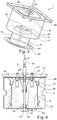
- FIG Figure 2 shows a transport and handling device 1 for a transmission part 2.
- the transmission part 2 is, for example, a gear of a planetary gear carrier 20, which in FIG Figure 1 is shown schematically.
- the transmission part 2 or gear has functional surfaces 71, 74.
- the functional surface 71 extends over a cylindrical section and on axial end faces of the transmission part 2 in the radial direction R partially inward.
- the transport and handling device 1 has at least one cylindrical wall 3, 8 protecting the functional surfaces 71, 74 in order to be able to transport the gear part 2 in the transport and handling device 1.
- the entire transmission part 2 or the functional surfaces 71, 74 of the transmission part 2 can be sensitive to chemical and mechanical environmental influences. Accordingly, the invention provides for the functional surfaces 71, 74 or the entire transmission part 2 to be shielded from mechanical effects and thus to be protected from damage.
- the gear part 2 and the wall 3, 8 are braced relative to one another by a tie rod 9 in the transport and handling device 1 so that the gear part 2 does not die due to a mass inertia i2 of the gear part 2 during accelerations a acting on the transport and handling device 1 Wall 3, 8 touched.
- the gear part 2 is clamped or can be clamped in such a way that a distance A3 is always maintained between the functional surface 71 and the wall 3.
- the transmission part 2 is axial between two spacer plates 44, 54 trapped.
- a clamping force necessary for clamping can be provided via the tie rod 9.
- another tensioning device not described in detail here can also be present or used.
- Planetary gears especially for aircraft turbines, are heavy, and individual gear parts 2 are correspondingly heavy.
- the handling and transport of the gear parts 2 is made more difficult by the fact that the gear parts 2 are easily damaged when trying to grip the gear part 2 from the outside.
- the transmission part 2 or the functional surface 71 should therefore at least not touch the walls 3, 4, 5 of the transport and handling device 1. Accordingly, the spacer plates 44 and 54 each have a diameter D44, D54 which is slightly smaller than a diameter D2 of the gear part 2 so that the spacer plates 44 and 54 do not protrude into the area of the functional surface 71.
- the functional surface 71 is held in the axial direction A above and below the gear part 2 at a distance A4 and A5 from the cover plate 50 and the base plate 40.
- the functional surfaces 74 can be arranged in the center of the transmission part 2.
- a shaft-hub connection is provided on this functional surface 74, which can be designed as a spline (not shown) (see FIG Figure 1 ).
- the functional surface 74 on the planetary gears 25 corresponds to a machined surface for receiving non- shown rolling elements of a rolling bearing or an outer sleeve of a rolling bearing 27 (see Figure 1 ).
- the functional surfaces 71, 74 are sensitive to environmental influences, in particular mechanical influences. Accordingly, the invention provides for mechanical influences from the functional surfaces to be shielded by the walls 3, 4, 5 and 8.
- the tie rod 9 optionally has an eyelet 95 or a hook which lies on an axis A9 which extends through a center of gravity S of the transport and handling device 1 and of the gear part 2.
- a wall 8 is provided or present on a centering mandrel 15 which is positioned centrally in the essentially hollow-cylindrical gear part 2.
- the wall 8 and / or the centering pin 15 are made of a softer material than the gear part 2, so that the functional surface 74 is not damaged.
- the centering mandrel 15 has a diameter D15.
- the diameter D15 is selected relative to an inner diameter DI2 of the transmission part 2 such that a fit is formed between the centering pin 15 and the transmission part 2 with a small amount of play.
- the centering pin 15 thus holds the gear part 2 centrally in the radial direction R.
- the centering pin 15 is penetrated in the middle by the tie rod 9.
- the tie rod 9 has a threaded bolt 91 and a threaded sleeve 92 that can be screwed to the threaded bolt 91.
- the threaded bolt 91 is connected to the centering pin 15 and the Threaded sleeve 92 extends along axis A9 through cover plate 50 and spacer plate 54.
- the threaded sleeve 92 rests positively on the cover plate 50 with a circumferential collar 19, so that a pretensioning force F can be applied to the cover plate 50.
- the pretensioning force F is generated by tightening the threaded sleeve 92 relative to the threaded bolt 91.
- the threaded bolt 91 is locked to the centering mandrel 15 via two nuts 96.
- washers can optionally be provided.
- the base plate 40 has an internal thread 97 for receiving the threaded bolt 91.
- the base plate 40 can thus be screwed onto the transport and handling device 1 from below.
- the base plate 40 is in two parts; the actual axial support of the gear part 2 is provided by the spacer plate 44 arranged between the base plate 40 and the gear part 2, which is smaller than the base plate 40 when viewed in the radial direction R.
- the threaded sleeve 92 can be tightened or screwed in through a corresponding torque-transmitting area on the collar 19, which is not shown.
- the tightening or screwing in of the threaded sleeve 92 can optionally take place additionally or alternatively on the eyelet 95.
- the centering mandrel 15 On an upper side 16 facing the cover plate 50, the centering mandrel 15 has a centering cone 17 which tapers conically towards the upper side 16. The centering cone 17, if necessary, facilitates the introduction of the centering mandrel 15 into the transmission part 2 in accordance with FIG Figure 3 .
- centering cone 29 enables access to an upper nut 29 with which the centering mandrel 15 is fastened to the threaded bolt 91 of the tie rod 9.
- the cover plate 50 When the cover plate 50, on which a sleeve 12 is optionally arranged, is brought closer to the gear part 2 or the centering pin 15 in order to brace the cover plate 50 relative to the centering pin 15, the cover plate 50 hides the view of the threaded bolt 91 the threaded bolt 91 extends out of an inner cone 29, which facilitates the introduction of the threaded sleeve 92 and access to the upper nut 96.
- the cover plate 50 can also be positioned relative to the centering mandrel 15 via guide bolts 18.
- the guide pins 18 extend counter to the axial direction A into bores 28 in the centering pin 15.
- the guide pins 18 are fastened to the cover plate 50 by means of screws 22.
- FIG Figure 4 An exemplary embodiment with a transmission part 2 that is partially accessible from the outside is shown in FIG Figure 4 shown. At least the double helical toothing 11 is accessible from the outside in order to be able to carry out certain manufacturing processes.
- the tie rod 9 is non-positively connected at a distal end 93 to a spacer plate 44 which holds the transmission part 2 and which supports the transmission part 2 in the axial direction A.
- the threaded bolt 91 is axially fixed with a nut 98 on the side of the spacer plate 44 facing away from the transmission part 2.
- the transmission part 2 is clamped between the cover plate 50 and the base plate 40 along the axial direction A.
- the spacer plate 44 closes the transmission part 2 towards the bottom, so that no media and no dirt can get to the inner functional surface 74.
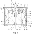
- the nut 98 can be removed and replaced by the base plate 40, if necessary with the sleeve 12 being attached to the cover plate 50 at the same time, accordingly Figure 5 .
- the cover plate 44 can be understood as a plate which is arranged on the base plate 40 ( Figure 5 ).
- the plate or cover plate 44 can represent a support surface for a gear part 2, which makes it possible for the gear part 2 to be able to be arranged without contact, ie at a distance from the base plate 40, in that there is a gap 99 between the gear part 2 and the base plate 40 arranged on the plate 44 .
- the formed gap 99 enables functional surfaces 71, 74 of the transmission part 2 to be arranged without contact or at a distance from the base plate 40, whereby damage during transport and handling of the transmission part 2 can be prevented.
- the base plate 40 and plate 44 are formed in one piece.
- the base plate 40 is designed in a stepped manner to provide a gap 99.
- the base plate 40 and plate 44 can also be designed as separate components.
- the plate 44 has a smaller diameter than the base plate 40 in order to provide a gap 99.
- the base plate 40 comprises a plate 44. It can also be possible for the plate 44 to comprise a base plate 40.
- a spacer plate 54 can be provided in an analogous manner ( Figure 4 ), which is arranged on the cover plate 50.
- the cover plate 54 or plate can represent a support surface for a gear part 2, which makes it possible for the gear part 2 to be able to be arranged without contact or at a distance from the cover plate 50 in that a gap 100 is present between the gear part arranged on plate 54 and the cover plate 50.
- cover plate 50 and spacer plate 54 or plate 54 are formed in one piece.
- the cover plate 50 is designed in a stepped manner to provide a gap 100.
- cover plate 50 and plate 54 can also be designed as separate components.
- the plate 54 has a smaller diameter than the base plate 13 in order to provide a gap 100.
- the guide pins 18 point accordingly Figure 4 optionally expandable sleeve sections 21, which are stretched apart by screwing in the screws 22, the expandable sleeve sections 21 penetrating into corresponding bores 28 on the top 16 of the centering mandrel 15 and when screwing in the screws 22 through the Expanding apart creates a frictional connection between the centering mandrel 15 and the cover plate 50 and the spacer plate 54.
- the centering mandrel 15 can be fastened with its upper side 16 to the cover plate 50.
- the gear part 2 fastened with the centering mandrel 15 can thus be moved freely without the sensitive functional surfaces 71, 74 having to be touched. This can be necessary, for example, to initiate processing steps.
- gear part can also be aligned with the cover plate 50 and the centering mandrel 15 relative to the planetary gear in order to mount it.
- FIG Figure 5 An embodiment with an inaccessible gear part 2 is shown in FIG Figure 5 shown.
- the tie rod 9 is non-positively connected at a distal end 93 to a base plate 40, the gear part 2 being clamped between the cover plate 50 and the base plate 40 along the axial direction A.
- the base plate 40 has a bevel 31 on the outside circumference, which facilitates centering of the sleeve 12 relative to the base plate 40.
- a bevel 32 facing the base plate 40 is also arranged on the sleeve 12.
- the distance A3 between the gear part 2 and the sleeve is selected so that the gear part 2 does not touch the wall 3 of the sleeve 12 even with greater accelerations a of up to 5 g.
- the transport and handling device 1 for a transmission part 2 thus has at least one wall 3, 4, 5 ( Figures 2 , 4th and 5 ).
- a gear part 2 is between two spacer plates 44, 54 ( Figures 2 , 4th and 5 ) fixable. Between at least one functional surface 71, 74 ( Figure 1 ) and at least one wall 3, 4, 5 there is a distance A3, A4, A5 ( Figures 2 , 4th and 5 ).
- the two spacer plates 44, 54 are arranged vertically to one another.
- the transmission part 2 is arranged between the spacer plates.
- a transport and handling device 1 is provided, in particular for a transmission part 2.
- the transmission part 2 has functional surfaces 71, 74.
- the gear part 2 is placed over a centering pin 15, which is then positioned centrally in the essentially hollow-cylindrical gear part 2, the centering pin 15 being penetrated centrally by the tie rod 9.
- the gear part 2 rests on at least one spacer plate 44; the spacer plate 44 preferably holds the functional surface 71 at a distance A4 from the base plate 40.
- the upper cover plate 50 and the spacer plate 54 are in the in Figure 5 illustrated embodiment integrally connected to one another.
- the threaded sleeve 92 rests positively on the cover plate 50 in an axial direction A in a force-absorbing manner, the cover plate 50 being positionable relative to the centering mandrel 15 via guide bolts 18.
- the unit consisting of the cover plate 50, the sleeve 12, the guide bolts 18 and the threaded sleeve 92 is now slipped over the gear part 2 in a further step until the guide bolts 18 completely penetrate the bores 28 and the sleeve 12 is flush with the base plate 40 .
- the threaded sleeve 92 is screwed onto the threaded bolt 91, the threaded bolt 91 being connected to the centering mandrel 15 and the threaded sleeve 92 extending through a cover plate 50 and the threaded sleeve 92 resting positively on the cover plate 50 with a circumferential collar 19.
- the centering pin 15, which is arranged in contact with the base plate 40 or the spacer plate 44, comprises bores 28, the unit comprising a cover plate 13, a sleeve 12 and a threaded sleeve 92 additionally comprising guide bolts 18, the Guide pins 18 preferably completely penetrate into the bores 28 when slipped over according to step b).
- the gear part 2 is placed on the spacer plate 44 in step a) in such a way that the spacer plate 44 holds the functional surface 71 at a distance A4 from the base plate 40.
- the transmission part 2 can be protected particularly effectively against damage.
- the cover plate 50 has an optional indentation 33 in which the collar 19 of the threaded sleeve 92 lies.
- the tie rod 9 is braced in the transport and handling device 1 and clamps the transmission part 2.
- the gear part 2 is clamped axially via the guide bolts 18 and the cover plate 50 in such a way that the gear part 2 does not touch the wall 3 due to a mass inertia i2 of the gear part 2 during accelerations a acting on the transport and handling device 1.
- the functional surfaces 71, 74 are protected from mechanical and chemical influences.
- a unit can also be provided which comprises a cover plate 50 and a sleeve 12 or which is formed by a cover plate 50 and a sleeve 12.
- the unit may further include a floor panel 40.
- the unit can furthermore comprise a centering pin 15.
- a receiving space can also be understood and described as a volume, in particular a transport volume of the transport and handling device.
- the invention also relates to a transport and handling device for gear parts 1, comprising at least one base plate 40 and a cover plate 50, further comprising at least one plate 44 which is in contact with, in particular connected to, the base plate 40 and comprising at least one further plate 54 which is in contact with, in particular connected to, the cover plate 50, the plates 44, 54 each having a smaller radial diameter than the base plate 40 and cover plate 50, or wherein the base plate 40 and / or the cover plate 50 is or are step-like, wherein at least one centering pin 15 is furthermore included, which is arranged on the base plate 40 or the plate 44, wherein at least one wall 3, 8 is included, and a sleeve 12 is furthermore included, which can enclose a gear part 2 at least in sections on the base plate 40 and / or can be placed on the plate and wherein a tensioning device, in particular a tie rod r 9 is included.
- step-like means that at least one step is present.
- a step can also be understood as a height difference. Such a height difference can be formed or present, for example, between base plate 40 and plate 44 or between cover plate 50 and plate 54.
- a transport and handling device designed in this way can provide particularly efficient protection for transmission parts, enable especially for functional surfaces of transmission parts.
- the bottom plate 40 can be a spacer plate 44.
- the spacer plate 44 can be a base plate 40.
- the base plate 40 is in two parts; the actual axial support of the gear part 2 takes place on a spacer plate 44, which is arranged between the base plate 40 and the gear part 2 and is smaller than the base plate 40 when viewed in the radial direction R.
- Base plate 40 and spacer plate 44 can also be designed as a one-piece component.
- Cover plate 50 and base plate 40 are arranged in the vertical direction, in particular essentially parallel to one another.
- Spacer plate 44 and spacer plate 54 are arranged in the vertical direction, in particular essentially parallel to one another.
Landscapes
- Engineering & Computer Science (AREA)
- Mechanical Engineering (AREA)
- Retarders (AREA)
- General Details Of Gearings (AREA)
Applications Claiming Priority (1)
| Application Number | Priority Date | Filing Date | Title |
|---|---|---|---|
| DE102020000612 | 2020-01-30 |
Publications (1)
| Publication Number | Publication Date |
|---|---|
| EP3858762A1 true EP3858762A1 (fr) | 2021-08-04 |
Family
ID=74236096
Family Applications (1)
| Application Number | Title | Priority Date | Filing Date |
|---|---|---|---|
| EP21153329.4A Pending EP3858762A1 (fr) | 2020-01-30 | 2021-01-25 | Dispositif de transport et de manutention d'un composant de transmission, ainsi que procédé de transport et de manipulation des composants de transmission |
Country Status (2)
| Country | Link |
|---|---|
| EP (1) | EP3858762A1 (fr) |
| DE (1) | DE102021101545A1 (fr) |
Citations (5)
| Publication number | Priority date | Publication date | Assignee | Title |
|---|---|---|---|---|
| US2828857A (en) * | 1954-03-25 | 1958-04-01 | Southern Gravure Service Inc | Shipping container for printing cylinders |
| DE6806220U (de) * | 1968-11-08 | 1969-03-13 | Menschner Textil Johannes | Verpackungsbehaelter, vornehmlich fuer kett- und teilbaeume. |
| US20070023303A1 (en) * | 2005-07-27 | 2007-02-01 | Garry Templeton | Packaging |
| EP2070842A2 (fr) * | 2007-12-14 | 2009-06-17 | Fritz Schäfer GmbH | Support d'outil, en forme de récipient plastique |
| EP2355115A1 (fr) * | 2010-02-08 | 2011-08-10 | ABB Technology AG | Boîtier de transport pour une bobine ou un bloc de bobinage |
-
2021
- 2021-01-25 EP EP21153329.4A patent/EP3858762A1/fr active Pending
- 2021-01-25 DE DE102021101545.6A patent/DE102021101545A1/de active Pending
Patent Citations (5)
| Publication number | Priority date | Publication date | Assignee | Title |
|---|---|---|---|---|
| US2828857A (en) * | 1954-03-25 | 1958-04-01 | Southern Gravure Service Inc | Shipping container for printing cylinders |
| DE6806220U (de) * | 1968-11-08 | 1969-03-13 | Menschner Textil Johannes | Verpackungsbehaelter, vornehmlich fuer kett- und teilbaeume. |
| US20070023303A1 (en) * | 2005-07-27 | 2007-02-01 | Garry Templeton | Packaging |
| EP2070842A2 (fr) * | 2007-12-14 | 2009-06-17 | Fritz Schäfer GmbH | Support d'outil, en forme de récipient plastique |
| EP2355115A1 (fr) * | 2010-02-08 | 2011-08-10 | ABB Technology AG | Boîtier de transport pour une bobine ou un bloc de bobinage |
Also Published As
| Publication number | Publication date |
|---|---|
| DE102021101545A1 (de) | 2021-08-05 |
Similar Documents
| Publication | Publication Date | Title |
|---|---|---|
| EP2822715B1 (fr) | Liaison d'outil | |
| EP3501733B1 (fr) | Dispositif de finition vibratoire d'une roue de véhicule et procédé de fixation d'une roue de véhicule dedans | |
| DE102019134138A1 (de) | Schnellverbindungsstücke für umrüstbare transportgutabfertigungsbaugruppen | |
| DE102016209846A1 (de) | Keilsicherungsmutteranordnung | |
| DE102013206577A1 (de) | Verfahren zur Festigung und Kalibrierung eines Rohrabschnittes | |
| EP3858761B1 (fr) | Dispositif de transport et de manutention d'un composant de transmission, ainsi que procédé de transport et de manipulation des composants de transmission | |
| DE202014008275U1 (de) | Spannsystem | |
| EP3858762A1 (fr) | Dispositif de transport et de manutention d'un composant de transmission, ainsi que procédé de transport et de manipulation des composants de transmission | |
| EP2722465B1 (fr) | Écrou de serrage rapide | |
| DE2919179C3 (de) | Diebstahlsicherung für Kraftfahrzeuge | |
| DE102021108566A1 (de) | Handhabungsvorrichtung | |
| DE102012218637A1 (de) | Transportverpackung für ein ringförmiges Lagerteil | |
| DE102007034198A1 (de) | Lenkradschloß | |
| DE102014106344A1 (de) | Befestigungsanordnung | |
| DE102011116920B4 (de) | Sicherungsvorrichtung für Container zum Sichern großer Behälter | |
| DE102018206028A1 (de) | Blattfederanbindung | |
| DE102021111705A1 (de) | Seitenführung und Frachtdeck eines Flugzeugs | |
| EP2979805B1 (fr) | Dispositif de protection pour un corps creux longitudinal avec deux demi coques et un chapeau ; methode de pose d'un tel dispositif de protection sur un corps creux | |
| EP2735370A1 (fr) | Dispositif de remplacement d'une pièce d'usure | |
| EP2900043B1 (fr) | Boîtier-support de logement d'électronique | |
| DE102019127011B4 (de) | Montageanordnung für eine Cockpit-Montage | |
| DE102011114863B4 (de) | Baugruppe für eine Anlage zum Einbau in einem Fahrzeug | |
| DE102019102017A1 (de) | Hebevorrichtung und Verfahren zum Handhaben eines Batteriemoduls, Verwendung einer Hebevorrichtung und System aus Hebevorrichtung und Batteriemodul | |
| DE102008061220B4 (de) | System zum Befestigen wenigstens einer weiteren Komponente an einer Kurbelwelle einer Brennkraftmaschine | |
| DE102018122701A1 (de) | Haltersystem zur Befestigung eines Behälters an einem Fahrzeug |
Legal Events
| Date | Code | Title | Description |
|---|---|---|---|
| PUAI | Public reference made under article 153(3) epc to a published international application that has entered the european phase |
Free format text: ORIGINAL CODE: 0009012 |
|
| STAA | Information on the status of an ep patent application or granted ep patent |
Free format text: STATUS: THE APPLICATION HAS BEEN PUBLISHED |
|
| AK | Designated contracting states |
Kind code of ref document: A1 Designated state(s): AL AT BE BG CH CY CZ DE DK EE ES FI FR GB GR HR HU IE IS IT LI LT LU LV MC MK MT NL NO PL PT RO RS SE SI SK SM TR |
|
| STAA | Information on the status of an ep patent application or granted ep patent |
Free format text: STATUS: REQUEST FOR EXAMINATION WAS MADE |
|
| 17P | Request for examination filed |
Effective date: 20211103 |
|
| RBV | Designated contracting states (corrected) |
Designated state(s): AL AT BE BG CH CY CZ DE DK EE ES FI FR GB GR HR HU IE IS IT LI LT LU LV MC MK MT NL NO PL PT RO RS SE SI SK SM TR |
|
| RAP3 | Party data changed (applicant data changed or rights of an application transferred) |
Owner name: AEROSPACE TRANSMISSION TECHNOLOGIES GMBH |
|
| STAA | Information on the status of an ep patent application or granted ep patent |
Free format text: STATUS: EXAMINATION IS IN PROGRESS |
|
| 17Q | First examination report despatched |
Effective date: 20230714 |
|
| REG | Reference to a national code |
Ref country code: DE Ref legal event code: R079 Free format text: PREVIOUS MAIN CLASS: B65D0085680000 Ipc: B65D0025100000 |
|
| RIC1 | Information provided on ipc code assigned before grant |
Ipc: B65D 25/10 20060101AFI20260312BHEP Ipc: B65D 85/68 20060101ALI20260312BHEP Ipc: B65D 81/02 20060101ALI20260312BHEP |
|
| GRAP | Despatch of communication of intention to grant a patent |
Free format text: ORIGINAL CODE: EPIDOSNIGR1 |
|
| STAA | Information on the status of an ep patent application or granted ep patent |
Free format text: STATUS: GRANT OF PATENT IS INTENDED |