EP2070862B1 - Hebebühne für Kraftfahrzeuge mit Abgasabsaugung - Google Patents
Hebebühne für Kraftfahrzeuge mit Abgasabsaugung Download PDFInfo
- Publication number
- EP2070862B1 EP2070862B1 EP08021528A EP08021528A EP2070862B1 EP 2070862 B1 EP2070862 B1 EP 2070862B1 EP 08021528 A EP08021528 A EP 08021528A EP 08021528 A EP08021528 A EP 08021528A EP 2070862 B1 EP2070862 B1 EP 2070862B1
- Authority
- EP
- European Patent Office
- Prior art keywords
- suction
- lifting platform
- lifting
- slide
- lift
- Prior art date
- Legal status (The legal status is an assumption and is not a legal conclusion. Google has not performed a legal analysis and makes no representation as to the accuracy of the status listed.)
- Expired - Fee Related
Links
- 230000001360 synchronised effect Effects 0.000 claims description 2
- 238000000605 extraction Methods 0.000 description 2
- 239000007789 gas Substances 0.000 description 2
- 230000008878 coupling Effects 0.000 description 1
- 238000010168 coupling process Methods 0.000 description 1
- 238000005859 coupling reaction Methods 0.000 description 1
- 230000001419 dependent effect Effects 0.000 description 1
Images


Classifications
-
- B—PERFORMING OPERATIONS; TRANSPORTING
- B66—HOISTING; LIFTING; HAULING
- B66F—HOISTING, LIFTING, HAULING OR PUSHING, NOT OTHERWISE PROVIDED FOR, e.g. DEVICES WHICH APPLY A LIFTING OR PUSHING FORCE DIRECTLY TO THE SURFACE OF A LOAD
- B66F7/00—Lifting frames, e.g. for lifting vehicles; Platform lifts
- B66F7/02—Lifting frames, e.g. for lifting vehicles; Platform lifts with platforms suspended from ropes, cables, or chains or screws and movable along pillars
- B66F7/025—Lifting frames, e.g. for lifting vehicles; Platform lifts with platforms suspended from ropes, cables, or chains or screws and movable along pillars screw operated
-
- B—PERFORMING OPERATIONS; TRANSPORTING
- B08—CLEANING
- B08B—CLEANING IN GENERAL; PREVENTION OF FOULING IN GENERAL
- B08B15/00—Preventing escape of dirt or fumes from the area where they are produced; Collecting or removing dirt or fumes from that area
- B08B15/002—Preventing escape of dirt or fumes from the area where they are produced; Collecting or removing dirt or fumes from that area using a central suction system, e.g. for collecting exhaust gases in workshops
- B08B15/005—Preventing escape of dirt or fumes from the area where they are produced; Collecting or removing dirt or fumes from that area using a central suction system, e.g. for collecting exhaust gases in workshops comprising a stationary main duct with one or more branch units, the branch units being freely movable along a sealed longitudinal slit in the main duct
-
- B—PERFORMING OPERATIONS; TRANSPORTING
- B66—HOISTING; LIFTING; HAULING
- B66F—HOISTING, LIFTING, HAULING OR PUSHING, NOT OTHERWISE PROVIDED FOR, e.g. DEVICES WHICH APPLY A LIFTING OR PUSHING FORCE DIRECTLY TO THE SURFACE OF A LOAD
- B66F7/00—Lifting frames, e.g. for lifting vehicles; Platform lifts
- B66F7/02—Lifting frames, e.g. for lifting vehicles; Platform lifts with platforms suspended from ropes, cables, or chains or screws and movable along pillars
- B66F7/04—Lifting frames, e.g. for lifting vehicles; Platform lifts with platforms suspended from ropes, cables, or chains or screws and movable along pillars hydraulically or pneumatically operated
-
- B—PERFORMING OPERATIONS; TRANSPORTING
- B66—HOISTING; LIFTING; HAULING
- B66F—HOISTING, LIFTING, HAULING OR PUSHING, NOT OTHERWISE PROVIDED FOR, e.g. DEVICES WHICH APPLY A LIFTING OR PUSHING FORCE DIRECTLY TO THE SURFACE OF A LOAD
- B66F7/00—Lifting frames, e.g. for lifting vehicles; Platform lifts
- B66F7/28—Constructional details, e.g. end stops, pivoting supporting members, sliding runners adjustable to load dimensions
Definitions
- the invention relates to a lift for motor vehicles of the type specified in claim 1.
- the guntuncts forming DE 200 12 375 U1 shows a lift for motor vehicles with a suction channel, wherein the suction channel is connected to a vacuum source.
- this object is achieved according to the invention in that the suction channel is arranged vertically in the lifting platform, wherein a suction carriage is slidably disposed on the suction and wherein the suction carriage by means of a suction hose located on the lift on the lift Vehicle is connectable.
- the combination of the exhaust hose with a slidable in a suction channel suction carriage ensures that the suction can always be made in the Auspuffebene the vehicle and thus the suction hose is taken substantially from the path of the workers aligning work.
- the movements of the suction carriage in the suction channel can once be designed so that the suction carriage is moved, or vice versa, that the suction carriage is positioned stationary and the suction channel carries out the lifting and lowering movements, which in particular for underfloor lifts is used.
- the invention is characterized by a stationary suction slide with connection to the vacuum source and a synchronized with the lifting movement of the lift suction, especially for use in underfloor lifts from.
- a further embodiment of the invention consists in that at least one lifting column of the lifting platform is designed as a suction channel with a vacuum connection on the one hand and a suction hose connection on the other.
- the invention also provides that the lift is equipped with at least two suction ducts positioned on both sides.
- 1 lift for lifting a motor vehicle 2 is a so-called overhead lift, which is equipped with two lifting pylons 3 and 4 with pivoting arms 5, via a drive, whether via spindles or a hydraulic od.
- a drive whether via spindles or a hydraulic od.
- FIG. 1 4 As is clear from the Fig. 1 and 2 results in this representation example is the in Fig. 1 4 associated with a suction channel 6, which communicates with a vacuum source, which in Fig. 1 is indicated by an arrow 7.
- a suction carriage 8 On the suction channel 6, a suction carriage 8 is slidably disposed, wherein the suction channel 6 relative to the suction carriage 8, a seal, e.g. a lip seal having, in order to prevent as much as possible the suction of external air.
- a seal e.g. a lip seal having, in order to prevent as much as possible the suction of external air.
- the suction slide 8 also has a connection 9 for a Abgasabsaugschlauch 10, which is on the exhaust 11 of a Vehicle with the help of a corresponding mounting sleeve 12 can be plugged.
- the suction carriage 8 is operatively connected to a coupling element 13 on the vehicle lifting device 5, 5 a such that it performs the lifting movement of these elements, such that the suction carriage 8 in the embodiment of Fig. 1 and 2 always located at the height of the vehicle.
- this can be fastened to a boom 5, for example via a fastening clamp 14.
- a stationary suction carriage 8b is positioned in the upper area, which is operatively connected to a suction channel 6b, whereby the suction channel 6b can also be raised and lowered following the vehicle lifting movement, as can be seen from FIGS FIGS. 5 and 6 results.
- the suction channel 6b is guided in a guide rail 16.
- FIGS. 5 and 6 is indicated by small arrows 7b, that also here the stationary suction slide 8b is in communication with a vacuum source.
- Fig. 8 is still indicated that the Hubpylone 3b and 4b can be designed with the arms 5b simultaneously as a suction channel or include in its interior such a suction channel with.
- suction slide / Saugkanal Sken can also be provided on other lifts, such as on swivel stages u.
- the suction can be assigned to one or more of the pivoting or supporting arms.
Landscapes
- Life Sciences & Earth Sciences (AREA)
- Engineering & Computer Science (AREA)
- Geology (AREA)
- Mechanical Engineering (AREA)
- Structural Engineering (AREA)
- Load-Engaging Elements For Cranes (AREA)
- Forklifts And Lifting Vehicles (AREA)
- Handcart (AREA)
- Fire-Extinguishing By Fire Departments, And Fire-Extinguishing Equipment And Control Thereof (AREA)
Description
- Die Erfindung bezieht sich auf eine Hebebühne für Kraftfahrzeuge der im Anspruch 1 angegebenen Gattung.
- Hebebühnen gibt es in sehr unterschiedlichen Bauweisen, wobei hier die Zwei-Säulen-Überflur- bzw. Zwei-Säulen-Unterflurhebeanlage als Beispiel für die Erfindung herangezogen wird, beispielsweise eine solche Zwei-Säulen-Überflurhebebühne, wie sie in der
DE 21 30 653 A1 oder demDE 200 12 375 U1 beschrieben ist. - Natürlich können auch andere Hebebühnenarten erfindungsgemäß ausgerüstet werden.
- Da es Arbeiten an Fahrzeugen gibt, bei denen es nötig ist, dass die Motoren laufen, ist es bekannt, etwa in entsprechenden Hallen von Werkstätten über Kanalsysteme, sei es im Boden der Werkstatt oder im Deckenbereich der Werkstätten, Absaugschläuche anzubringen, die auf die Auspuffenden der Fahrzeuge aufsteckt werden können. Über entsprechende Vakuumquellen können dann die Abgase nach außen abgesaugt werden, so beschrieben in der
DE 24 60 621 B2 oder derJP 35-10 200 B2 DE 44 18 389 A1 oder dieDE 44 30 533 A1 . - Um wenigstens teilweise zu vermeiden, dass derartige Absaugschläuche auf dem Boden der Werkstatt während der Benutzung liegen, ist es auch bekannt, etwa an der Werkstatthallenwand galgenähnliche Schwenkarme vorzusehen, die mit Halteelementen für die Abgasschläuche versehen sind. Eine vergleichsweise aufwändige Art, um etwa Unfälle durch Stolpern über die Schläuche zu vermeiden. Die gattunctsbildende
DE 200 12 375 U1 zeigt eine Hebebühne für Kraftfahrzeuge mit einem Saugkanal, wobei der Saugkanal mit einer Vakuumguelle verbunden ist. - Hier setzt die Erfindung an, deren Aufgabe darin besteht, eine möglichst einfache Absaugung von Abgasen zu ermöglichen, und zwar unabhängig davon, in welchem Hubzustand sich das Fahrzeug im Bereich der Hebebühne befindet, wobei die Absaugung unabhängig von der Art und Gestaltung der heb- und senkbaren Elemente ist.
- Mit einer Hebebühne der eingangs bezeichneten Art wird diese Aufgabe gemäß der Erfindung dadurch gelöst, dass der Saugkanal im Bereich der Hebebühne vertikal angeordnet ist, wobei auf dem Saugkanal ein Saugschlitten verschiebbar angeordnet ist und wobei der Saugschlitten mittels eines Absaugschlauches am Auspuff des auf der Hebebühne befindlichen Fahrzeuges verbindbar ist.
- Durch die Kombination des Abgasschlauches mit einem in einem Saugkanal verschiebbaren Saugschlitten wird erreicht, dass die Absaugung immer in der Auspuffebene des Fahrzeuges vorgenommen werden kann und somit der Absaugschlauch im Wesentlichen aus dem Laufweg der die Arbeiten ausrichtenden Personen genommen ist.
- Ausgestaltungen der Erfindung ergeben sich aus den Unteransprüchen. Dabei kann zweckmäßig vorgesehen sein, dass zwischen den heb- und senkbaren Elementen der Hebebühne und dem Saugschlitten wenigstens ein Verbindungselement zum synchronen Bewegen des Saugschlittens mit der Hub- und Senkbewegung der Hebebühne vorgesehen ist.
- An dieser Stelle sei bemerkt, dass die Bewegungen des Saugschlittens im Saugkanal einmal so gestaltet sein können, dass der Saugschlitten bewegt wird, oder aber umgekehrt, dass der Saugschlitten ortsfest positioniert ist und der Saugkanal die Heb- und Senkbewegungen mit ausführt, was insbesondere bei Unterflurhebebühnen zum Einsatz kommt.
- Hierzu zeichnet sich die Erfindung durch einen ortsfesten Saugschlitten mit Anschluss an der Vakuumquelle und einem mit der Hubbewegung der Hebebühne synchronisierten Absaugkanal, insbesondere zum Einsatz bei Unterflurhebebühnen, aus.
- Eine weitere Ausgestaltung der Erfindung besteht darin, dass wenigstens eine Hubsäule der Hebebühne als Saugkanal mit Vakuumanschluss einerseits und Absaugschlauchanschluss andererseits ausgebildet ist.
- Da es mehr und mehr Fahrzeuge gibt, die mit zwei Auspuffanlagen ausgestattet sind, sieht die Erfindung auch vor, dass die Hebebühne mit wenigstens zwei auf beiden Seiten positionierten Absaugkanälen ausgerüstet ist.
- Weitere Vorteile der Erfindung ergeben sich aufgrund der nachfolgenden Beschreibung sowie anhand der Zeichnung. Diese zeigt in
- Fig. 1
- eine angedeutete Überflurhebebühne mit einem zuge- ordneten Absaugkanal in Seitenansicht,
- Fig. 2
- die gleiche Hebebühne in Aufsicht gemäß Pfeil II in in
Fig. 1 , - Fig. 3
- in der Darstellungsweise gemäß
Fig. 1 eine Überflur- hebebühne mit zwei Saugkanälen, - Fig. 4
- eine Aufsicht auf
Fig. 3 gemäß Pfeil IV inFig. 3 , - Fig. 5
- eine Seitenansicht einer Unterflurhebebühne,
- Fig. 6
- eine Seitenansicht wie
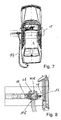
Fig. 5 mit angehobenem Fahr- zeug, - Fig. 7
- eine Aufsicht auf
Fig. 5 gemäß Pfeil VII inFig. 5 sowie in - Fig. 8
- eine vergrößerte Detaildarstellung nach
Fig. 7 . - Bei der in den
Fig. 1 und 2 dargestellten, allgemein mit 1 bezeichneten Hebebühne zum Anheben eines Kraftfahrzeuges 2 handelt es sich um eine sogenannte Überflurhebebühne, die mit zwei Hubpylonen 3 und 4 mit verschwenkbaren Armen 5 ausgerüstet ist, die über einen Antrieb, sei es über Spindeln oder über eine Hydraulik od. dgl., gehoben und gesenkt werden können, um damit das Fahrzeug 2 in die gewünschte Position zu bringen, was hier nicht näher dargestellt ist. - Wie sich aus den
Fig. 1 und 2 ergibt, ist in diesem Darstellungsbeispiel dem inFig. 1 linken Pylonen 4 ein Saugkanal 6 zugeordnet, der mit einer Vakuumquelle in Verbindung steht, was inFig. 1 durch einen Pfeil 7 angedeutet ist. - Auf dem Saugkanal 6 ist ein Saugschlitten 8 verschiebbar angeordnet, wobei der Saugkanal 6 gegenüber dem Saugschlitten 8 eine Dichtung, z.B. eine Lippendichtung, aufweist, um möglichst das Einsaugen von Fremdluft zu verhindern.
- Der Saugschlitten 8 weist darüber hinaus einen Anschluss 9 für einen Abgasabsaugschlauch 10 auf, der auf den Auspuff 11 eines Fahrzeuges mit Hilfe einer entsprechenden Montagetülle 12 aufgesteckt werden kann.
- Der Saugschlitten 8 ist mit einem Kupplungselement 13 an der Fahrzeughubeinrichtung 5, 5a wirkmäßig derart verbunden, dass er die Hubbewegung dieser Elemente mit vollführt, derart, dass sich der Saugschlitten 8 beim Ausführungsbeispiel der
Fig. 1 und 2 immer auf der Höhe des Fahrzeugs befindet. Um den Schlauch 10 mitzuführen, kann dieser beispielsweise über eine Befestigungsschelle 14 an einem Ausleger 5 befestigt sein. - Das Ausführungsbeispiel nach den
Fig. 3 und 4 entspricht im Wesentlichen demjenigen derFig. 1 und 2 . Hier sind allerdings beide Pylonen 3 und 4 durch einen entsprechenden Saugkanal 6, 6a ausgerüstet. Die baugleichen Elemente tragen die gleichen Bezugszeichen wie inFig. 1 , ggf. ergänzt durch den kleinen Buchstaben "a". - Ist bei den
Fig. 1 und 2 der Saugkanal 6 an der dem Fahrzeug abgewandten Rückseite des Pylonen 4 positioniert, so sind bei dem Ausführungsbeispiel derFig. 3 und 4 die Saugkanäle 6 und 6a an der einen Seitenwand der Pylonen 3 und 4 befestigt. - Bei den Ausführungsbeispielen der
Fig. 5 ff. handelt es sich um die Darstellung einer sogenannten Unterflurhebeanlage, wobei in den Figuren aus Darstellungsgründen die Hubmechanik für das Fahrzeug 2 nicht näher dargestellt ist. - In der diese Elemente aufnehmenden Grube 15 ist im oberen Bereich ein ortsfester Saugschlitten 8b positioniert, der mit einem Saugkanal 6b wirkmäßig in Verbindung steht, wobei der Saugkanal 6b der Fahrzeughubbewegung folgend ebenfalls heb- und senkbar ist, wie sich dies aus den
Fig. 5 und 6 ergibt. Um dieser Hub- und Senkbewegung folgen zu können, ist der Saugkanal 6b in einer Führungsschiene 16 geführt. - In den
Fig. 5 und 6 ist noch durch kleine Pfeile 7b angedeutet, dass auch hier der ortsfeste Saugschlitten 8b mit einer Vakuumquelle in Verbindung steht. - In
Fig. 8 ist noch angedeutet, dass die Hubpylone 3b und 4b mit den Auslegern 5b gleichzeitig als Saugkanal gestaltet sein können bzw. in ihrem Inneren einen solchen Saugkanal mit umfassen. - Entsprechende Saugschlitten/Saugkanaleinrichtungen können auch an anderen Hebebühnen vorgesehen sein, etwa an Schwenkbühnen u. dgl., wobei in solchen Fällen beispielsweise bei einer zentralen Hubhydraulik die Absaugleitungen einem oder mehreren der Schwenk- bzw. Tragarme zugeordnet sein können.
Claims (5)
- Hebebühne für Kraftfahrzeuge mit einem Saugkanal (12), wobei der Saugkanal (12) mit einer Vakuumguelle verbunden ist,
dadurch gekennzeichnet,
dass der Saugkanal (6) im Bereich der Hebebühne (1) vertikal angeordnet ist, wobei auf dem Saugkanal (6) ein Saugschlitten (8) verschiebbar angeordnet ist und wobei der Saugschlitten (8) mittels eines Absaugschlauches (10) am Auspuff (11) des auf der Hebebühne befindlichen Fahrzeuges (2) verbindbar ist. - Hebebühne nach Anspruch 1,
dadurch gekennzeichnet,
dass zwischen den heb- und senkbaren Elementen (5,5a) der Hebebühne (1) und dem Saugschlitten (8) wenigstens ein Verbindungselement (13) zum synchronen Bewegen des Saugschlittens (8) mit der Hub- und Senkbewegung der Hebebühne (1) vorgesehen ist. - Hebebühne nach Anspruch 1 oder 2,
gekennzeichnet durch
einen ortsfesten Saugschlitten (8b) mit Anschluss an der Vakuumquelle (7b) und einem mit der Hubbewegung der Hebebühne (1b) synchronisierbewegbaren Saugkanal (6b), insbesondere zum Einsatz bei Unterflurhebebühnen. - Hebebühne nach Anspruch 1 oder einem der folgenden,
dadurch gekennzeichnet,
dass wenigstens eine Hubsäule (3) der Hebebühne (1) als Saugkanal mit Vakuumanschluss einerseits und Absaugschlauchanschluss andererseits ausgebildet ist. - Hebebühne nach Anspruch 1 oder einem der folgenden,
dadurch gekennzeichnet,
dass die Hebebühne (1a) mit wenigstens zwei auf beiden Seiten positionierten Absaugkanälen (6,6a) ausgerüstet ist.
Applications Claiming Priority (1)
| Application Number | Priority Date | Filing Date | Title |
|---|---|---|---|
| DE202007017404U DE202007017404U1 (de) | 2007-12-13 | 2007-12-13 | Hebebühne für Kraftfahrzeuge mit Abgasabsaugung |
Publications (3)
| Publication Number | Publication Date |
|---|---|
| EP2070862A2 EP2070862A2 (de) | 2009-06-17 |
| EP2070862A3 EP2070862A3 (de) | 2010-02-03 |
| EP2070862B1 true EP2070862B1 (de) | 2012-04-11 |
Family
ID=40352053
Family Applications (1)
| Application Number | Title | Priority Date | Filing Date |
|---|---|---|---|
| EP08021528A Expired - Fee Related EP2070862B1 (de) | 2007-12-13 | 2008-12-11 | Hebebühne für Kraftfahrzeuge mit Abgasabsaugung |
Country Status (2)
| Country | Link |
|---|---|
| EP (1) | EP2070862B1 (de) |
| DE (1) | DE202007017404U1 (de) |
Families Citing this family (5)
| Publication number | Priority date | Publication date | Assignee | Title |
|---|---|---|---|---|
| CN104045019B (zh) * | 2013-03-11 | 2016-08-03 | 上海微电子装备有限公司 | 一种同步提升移入移出机构 |
| CN104030190B (zh) * | 2014-06-23 | 2016-03-23 | 山东电力建设第一工程公司 | 立式大口径管道安装同步提升平台 |
| IT201700112259A1 (it) * | 2017-10-28 | 2019-04-28 | Mauro Romagnuolo | Carrello aereo scorrevole atto all'evacuazione di gas e fumi |
| CN112093714A (zh) * | 2020-07-31 | 2020-12-18 | 盐城工学院 | 一种气动抬升机构 |
| CN114227625A (zh) * | 2022-01-12 | 2022-03-25 | 天津恒亚通机械有限公司 | 一种用于检修新能源汽车的检修装置 |
Family Cites Families (7)
| Publication number | Priority date | Publication date | Assignee | Title |
|---|---|---|---|---|
| DE2130653A1 (de) * | 1971-06-21 | 1972-12-28 | Hofmann Maschf Geb | Zwei-Saeulen-UEberflur-Hebebuehne |
| DE2460621C3 (de) * | 1974-12-20 | 1978-04-20 | Emil 2000 Hamburg Drestler | Fahrzeughebevorrichtung |
| DE4418389A1 (de) * | 1994-05-26 | 1996-07-11 | Fuhrmann Ulrich | Pneumatischer Vakuum-Schlauchhalter für automatische Entkupplung mit stationärer vollautomatischer Druckluft-Ladestation |
| DE4430533A1 (de) * | 1994-08-27 | 1996-02-29 | Klaus Piwko | Portal-Versorgungsanlage für Strom, Druckluft, Hochdruck-Staubabsaugung, Mitteldruck-Dämpfeabsaugung -System Saugschlitzkanal- und Werkzeuge, höhenverstellbar und verfahrbar für humane Arbeitsplatzgestaltung |
| DE29510480U1 (de) * | 1995-06-28 | 1995-12-21 | Ludscheidt GmbH, 44319 Dortmund | Vorrichtung zum Absaugen von Abgasen von sich an einer Arbeits- oder Prüfstrecke entlangbewegenden Kraftfahrzeugen |
| DE20012375U1 (de) * | 2000-07-17 | 2000-12-28 | AUTOPERKUTE Maschinenbau GmbH, 48432 Rheine | Hubvorrichtung, insbesondere Hebebühne für Kraftfahrzeuge |
| JP3510200B2 (ja) * | 2000-09-29 | 2004-03-22 | 東洋工業株式会社 | 排気ガス吸引装置 |
-
2007
- 2007-12-13 DE DE202007017404U patent/DE202007017404U1/de not_active Expired - Lifetime
-
2008
- 2008-12-11 EP EP08021528A patent/EP2070862B1/de not_active Expired - Fee Related
Also Published As
| Publication number | Publication date |
|---|---|
| EP2070862A3 (de) | 2010-02-03 |
| DE202007017404U1 (de) | 2009-04-16 |
| EP2070862A2 (de) | 2009-06-17 |
Similar Documents
| Publication | Publication Date | Title |
|---|---|---|
| EP2070862B1 (de) | Hebebühne für Kraftfahrzeuge mit Abgasabsaugung | |
| EP1285878A1 (de) | Hebebühne, insbesondere mobile Hebebühne | |
| DE2040949A1 (de) | Rohrhandhabungsvorrichtung fuer OElbohrtuerme od.dgl. | |
| EP3825198A2 (de) | Selbstfahrender wagen für eine hochbahnähnliche tragstruktur, tragstruktur und transportsystem | |
| DE2644022C2 (de) | Vorrichtung zum Abstellen von Fahrzeugen auf mindestens zwei übereinander angeordneten Plattformen | |
| DE112016007065T5 (de) | Aufzugsvorrichtung | |
| DE102011050753A1 (de) | Sitzvorrichtung für Montage- oder Fertigungsstraßen | |
| EP2218632B1 (de) | Schubplatteneinheit | |
| DE202020102988U1 (de) | Werkstückträgersystem | |
| AT518319B1 (de) | Schweißaggregat zum Verschweißen von Schienen eines Gleises | |
| DE102019006403A1 (de) | Transportsystem sowie Verfahren zum Transportieren eines Kraftwagenrohbaus | |
| DE20120958U1 (de) | Armlehne für ein Kraftfahrzeug | |
| DE102009026061B4 (de) | Schwenkbare Dacharbeitsbühne | |
| DE1530299A1 (de) | Stuetzbock fuer das vordere Ende auf Schienenfahrzeuge | |
| DE7817731U1 (de) | Torantrieb, insbesondere fuer garagentore, mit einem elektrischen antriebsmotor | |
| EP1714937B1 (de) | Teleskopierbares Lastaufnahmemittel | |
| DE4020715A1 (de) | Industriestapler und deren schlauchfuehrungen | |
| DE2949120C2 (de) | Grubenhebevorrichtung für Lastkraftwagen | |
| DE102016216768A1 (de) | Fertigungsvorrichtung | |
| DE9406570U1 (de) | Vorrichtung zur Leitungsführung | |
| DE102004050975B4 (de) | Konsole für eine Unterdruckspanneinrichtung | |
| DE19643810A1 (de) | Handhabungsgerät für ein Brückenlegesystem | |
| DE3149639A1 (de) | Schraegaufzug zum foerdern von lasten | |
| DE2053299A1 (de) | Schwenkstufe für Schienenfahrzeuge | |
| DE102011103245A1 (de) | Sitzvorrichtung für eine Fahrzeugfertigungslinie, umfassend einen Sitzarm mit einem Sitzelement und einen Hilfsarm mit einer Einrichtung zur Aufnahme von Arbeitsmitteln und/oder Werkzeugen |
Legal Events
| Date | Code | Title | Description |
|---|---|---|---|
| PUAI | Public reference made under article 153(3) epc to a published international application that has entered the european phase |
Free format text: ORIGINAL CODE: 0009012 |
|
| AK | Designated contracting states |
Kind code of ref document: A2 Designated state(s): AT BE BG CH CY CZ DE DK EE ES FI FR GB GR HR HU IE IS IT LI LT LU LV MC MT NL NO PL PT RO SE SI SK TR |
|
| AX | Request for extension of the european patent |
Extension state: AL BA MK RS |
|
| PUAL | Search report despatched |
Free format text: ORIGINAL CODE: 0009013 |
|
| AK | Designated contracting states |
Kind code of ref document: A3 Designated state(s): AT BE BG CH CY CZ DE DK EE ES FI FR GB GR HR HU IE IS IT LI LT LU LV MC MT NL NO PL PT RO SE SI SK TR |
|
| AX | Request for extension of the european patent |
Extension state: AL BA MK RS |
|
| 17P | Request for examination filed |
Effective date: 20100720 |
|
| 17Q | First examination report despatched |
Effective date: 20100819 |
|
| AKX | Designation fees paid |
Designated state(s): DE |
|
| GRAP | Despatch of communication of intention to grant a patent |
Free format text: ORIGINAL CODE: EPIDOSNIGR1 |
|
| GRAS | Grant fee paid |
Free format text: ORIGINAL CODE: EPIDOSNIGR3 |
|
| GRAA | (expected) grant |
Free format text: ORIGINAL CODE: 0009210 |
|
| AK | Designated contracting states |
Kind code of ref document: B1 Designated state(s): DE |
|
| REG | Reference to a national code |
Ref country code: DE Ref legal event code: R096 Ref document number: 502008006909 Country of ref document: DE Effective date: 20120606 |
|
| PLBE | No opposition filed within time limit |
Free format text: ORIGINAL CODE: 0009261 |
|
| STAA | Information on the status of an ep patent application or granted ep patent |
Free format text: STATUS: NO OPPOSITION FILED WITHIN TIME LIMIT |
|
| 26N | No opposition filed |
Effective date: 20130114 |
|
| REG | Reference to a national code |
Ref country code: DE Ref legal event code: R097 Ref document number: 502008006909 Country of ref document: DE Effective date: 20130114 |
|
| PGFP | Annual fee paid to national office [announced via postgrant information from national office to epo] |
Ref country code: DE Payment date: 20191223 Year of fee payment: 12 |
|
| REG | Reference to a national code |
Ref country code: DE Ref legal event code: R119 Ref document number: 502008006909 Country of ref document: DE |
|
| PG25 | Lapsed in a contracting state [announced via postgrant information from national office to epo] |
Ref country code: DE Free format text: LAPSE BECAUSE OF NON-PAYMENT OF DUE FEES Effective date: 20210701 |