EP2070864A2 - Procédé destiné au fonctionnement d'un chariot de manutention - Google Patents
Procédé destiné au fonctionnement d'un chariot de manutention Download PDFInfo
- Publication number
- EP2070864A2 EP2070864A2 EP08021542A EP08021542A EP2070864A2 EP 2070864 A2 EP2070864 A2 EP 2070864A2 EP 08021542 A EP08021542 A EP 08021542A EP 08021542 A EP08021542 A EP 08021542A EP 2070864 A2 EP2070864 A2 EP 2070864A2
- Authority
- EP
- European Patent Office
- Prior art keywords
- load
- truck
- distance
- component
- drive wheel
- Prior art date
- Legal status (The legal status is an assumption and is not a legal conclusion. Google has not performed a legal analysis and makes no representation as to the accuracy of the status listed.)
- Granted
Links
Images




Classifications
-
- B—PERFORMING OPERATIONS; TRANSPORTING
- B66—HOISTING; LIFTING; HAULING
- B66F—HOISTING, LIFTING, HAULING OR PUSHING, NOT OTHERWISE PROVIDED FOR, e.g. DEVICES WHICH APPLY A LIFTING OR PUSHING FORCE DIRECTLY TO THE SURFACE OF A LOAD
- B66F17/00—Safety devices, e.g. for limiting or indicating lifting force
- B66F17/003—Safety devices, e.g. for limiting or indicating lifting force for fork-lift trucks
Definitions
- the present invention relates to a method for operating an industrial truck with at least one brakable drive wheel, wherein a permissible maximum speed of the industrial truck is determined as a function of a recorded load.
- the maximum achievable braking effect on this drive wheel or this axis is reduced.
- the braking distance can be influenced by varying the braking torque or the speed, other influencing factors are the direction of travel and the lifting height. An increase in the braking torque, however, makes sense only up to the point blocked by the braked wheel. Since the braking distance also depends on the speed and the direction from which the braking is to take place, a restriction of the speed can be considered, whereby a general reduction of the speed has a negative effect on the handling capacity of the truck.
- a generic method is for example from the EP 0 814 051 B1 known.
- a control signal for the maximum speed depending on the direction of travel and depending on the mass of the recorded load is changed such that when driving in the direction of a braked axle a higher maximum speed is allowed than when driving in the direction of a non-braked axle.
- the maximum achievable deceleration, which determines the maximum permissible speed is calculated as a function of the variables normal force between the roadway and the braked axle when the vehicle is stationary, the coefficient of friction and the total mass of the truck including the recorded load.
- the object of the invention is a method for the operation of a truck to provide in which the wheel contact forces can be determined easily and reliably.
- the invention proposes that the maximum speed is determined depending on a distance that is measured between a first and a second component of the truck and changes depending on the force acting on the brakable drive wheel wheel contact force, wherein the two components in Move the dependence of the recorded load relative to each other.
- the second component is a chassis portion of the vehicle on which the drive wheel is supported. It is preferred if the first component is an indirectly connected to the second component frame portion of the vehicle, preferably a guided around the drive wheel frame portion which is provided for fixing a housing cover.
- the selection of the two components is important insofar as their relative movement to each other must have an extent that can be detected reliably and precisely by a distance sensor. It is also essential that the two components under the inclusion of a load not one subject to the same deformation, so that the required and measurable change in distance results between them.
- a hysteresis can be determined for the measured distance, which depends on the direction of travel of the industrial truck and also on the measuring point.
- the distance between the two components for example, increases when braking in the direction of the braked drive wheel, and the distance is reduced at the same load, for example, with a braking in the direction of the load.
- the load torque caused by the recorded load can be determined as a function of the measured distance and its hysteresis. It is also proposed that the mass of the load taken be measured directly, preferably by measuring the hydraulic pressure. In combination with a pressure sensor in the hydraulic system, the contact forces can be checked for plausibility, because on the one hand there is an exact indication of the recorded load mass and on the other hand can be taken into account by the distance measurement influences the positioning of the mass on the Radaufstandskraft. Furthermore, a combined use of a pressure sensor and a distance sensor makes it possible to carry out an adjustment between distance sensor and pressure sensor whenever the pressure sensor outputs a value zero, that is, when no load is received and the load receiving means is arranged at a defined, in particular its lowest position. Further, when the load is picked up, the pressure sensor signal can be used to make a distinction as to whether the load has changed or whether the change in distance is hysteresis-related.
- the distance is preferable for the distance to be measured in a suitable operating state, preferably when the industrial truck is at a standstill.
- the measurement during the standstill in particular can be done several times to take into account the recording or settling of a load and to provide a distance value immediately before the start of driving, after the presence of a load and the acting load moment and optionally their mass and lifting height are determined.
- at standstill are still recorded, from which direction the braking took place to a standstill. It is also conceivable to carry out the distance measurements at creep speed of the vehicle or on routes where no appreciable relative movements occur.
- an undershot signal is generated when falling below a certain Radaufstandskraft.
- a non-permissible load case for example, if a per se permissible mass, which is unevenly distributed on the load receiving fork, subject to acceleration and raised to a level that leads to a strong reduction of the wheel contact force due to the acting load torque.
- the distance measurement between the two components can also contribute to increased safety during operation.
- the measured signals or values can be transmitted to a central control unit of the industrial truck, the control unit calculating the maximum speed.
- control unit in the case of detection of the underflow signal causes a corresponding operating state of the truck, preferably the standstill of the truck.
- the invention relates to an industrial truck with a central control unit for carrying out the method according to the invention.
- the truck comprises at least one brakable drive wheel, a height-adjustable load-receiving means and at least one distance sensor which is arranged on a first component of the truck that the distance to a second component can be determined, wherein the first and the second component in dependence a load received on load-receiving means are movable relative to each other.
- the control unit is preferably set up in such a way that, by evaluating the measured distance, it can determine a wheel contact force acting on the drive wheel and set a maximum speed for the industrial truck.
- the truck may have a load sensor, preferably hydraulic pressure sensor, which determines the mass of the recorded load. It is further proposed that it comprises a lifting height sensor for detecting the lifting height of the load receiving means or the load recorded.
- the signals of the load sensor and / or the lifting height sensor are transferable to the control unit and can be taken into account by the latter in determining the maximum speed.
- two distance sensors are provided which each detect a distance to the second component.
- the two sensors can be arranged on opposite sides of the second component. It is particularly advantageous if the two sensors are arranged diametrically opposite each other, with the second component extending between them.
- Fig. 1 shows an industrial truck in the form of an order picker 10 from above obliquely.
- the commissioner 10 has a mast 12, which is telescopically extendable in the vertical direction, along the mast 12 displaceable cab 14 and attached thereto load-carrying means in the form of a fork 16.
- the order picker 10 is a three-wheeled vehicle, with two front, neither driven still braked wheels or rollers 18, of which only the left roller is shown. Of course, these rollers can also be braked in other embodiments and optionally driven.
- a driven, braked and steerable wheel 22 In the rear area under a cover 20 is a driven, braked and steerable wheel 22, which is arranged centrally with respect to the width direction B.
- the fork 16 is relatively displaceable relative to the cab 14, and the cab 14 is slidable along the telescopic mast 12 from a lowered position to a position shown in dashed lines.
- a load moment LM which remains constant when the order picker 10 is stationary acts as the lifting height H, H 'increases.
- This load moment LM changes as a function of accelerations acting on the order picker 10, this load moment also depending on the position of the load 24, 24 'in the horizontal direction on the load fork 16.
- the load torque is correspondingly larger and the wheel contact force on the drive wheel 22 is further reduced. It is thus advantageous that not only the mass of the load 24, 24 'can be determined as accurately as possible, but also that the wheel contact force acting on the drive wheel 22 on the ground 26 can be determined as accurately as possible.
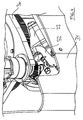
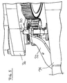
- the order picker 10 has at least one in the Fig. 5 Distance sensor 30 shown by way of example, which is attached to an angle bent carrier 32.
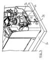
- This carrier 32 is, as in the Fig. 3 and 4 can be seen attached to a component 34 of the truck 10, which forms a housing for the drive wheel 22 and on which the cover 20 (FIG. Fig. 1 ) is attachable.
- the carrier 32 is shaped such that the distance sensor 30 is arranged substantially vertically below a carrier plate 36, via which the drive wheel 22 is supported on the chassis of the truck 10. Between the top of the sensor 30 and the underside of the plate 36, a distance A is present, which changes when receiving a load 24, 24 'on the fork 16 and is detected by the distance sensor 30.
- the change in the distance A is due to relative movements between the frame member 34 and the support 32 and the support plate 36 when a load 24, 24 'is received.
- the axle load acting on the drive wheel 22 increases or Radaufstandskraft with increasing mass of the recorded load 24 and at the same time reduces the distance A with increasing mass of the recorded load, since the frame member 34 of the support plate 36 by fractions of a millimeter approaches in the context of possible elastic deformation during load absorption.
- the measurement of the distance A which is in principle a deformation measurement, has a hysteresis, which makes itself noticeable in different directions depending on the direction of travel.
- Graph 40 shows the progression of the distance A in millimeters (right side scale) and the corresponding hysteresis-defining graphs 42 and 44. If a load of, for example, 600 kg is picked up and lifted to a certain lifting height, the distance is changed of 0.25 mm, wherein, taking into account the hysteresis depending on the driving or braking direction deformations of about 0.22 - 0.28 mm are possible.
- a load range of just over 500 kg to a little less than 700 kg can be assigned to the 0.25 mm spacing, which is shown in the diagram of FIG Fig. 6 is shown in dashed lines.
- the graphs 42, 44 shown here represent a hysteresis range HB for the distance A, which must be taken into account if the direction of travel is not taken into account in the calculation. If the direction of travel is taken into account, the hysteresis range HB can also be smaller, in particular halved. From the Fig. 6 Furthermore, the graph 46 can be seen, which shows the course of the force acting on the drive wheel 22 axle load or wheel contact force as a function of the recorded load.
- axle load decreases from just under 2000 kg to just under 1200 kg for loads from 0 to 1200 kg. Due to the course of the graphs 40, 46 it can also be seen that corresponding axle load values can also be assigned to a specific distance value, taking into account the hysteresis, so that a suitable maximum speed for the industrial truck can be determined, which ensures safe braking of the industrial truck recorded load allows.
- Fig. 7 is a diagram showing the corresponding measured distance values for different masses and different operating conditions.
- the truck is stationary and has taken no load.
- a load was taken, with the graph showing the graphs for five different loads from 0 to 1000 kg.
- the graphs have corresponding numbers 0, 400, 600, 800, 1000 to represent the mass in kilograms of the load taken up. It can be seen that at the instant LA, the distance A between the two components 34, 36 clearly decreases in all cases of load absorption (400 kg and greater) and also assumes different values as a function of the recorded load.
- the truck is in the direction of the load L ( Fig. 2 ) and decelerated in this direction at time LBR.
- the distance A only changes insignificantly with the loads 400 - 800 kg, but clearly decreases with the load of 1000 kg. From this position, the truck is now in the drive direction B ( Fig. 2 ) and then decelerated in that direction at time BBR. It can be seen with all loads (400, 600, 800 and 1000 kg) that the distance A becomes larger again due to the effective load moment LM. At time SA, the recorded load has been lowered again, and the distance A increases again to a value in the range of standstill S. From the diagram of Fig. 7 It is clear that the distance A varies depending on the driving or braking direction at the same load, causing the in the Fig. 6 is explained hysteresis HB.
- the truck may further comprise a pressure sensor (not shown) accommodated in the hydraulic system, which determines the mass of the recorded load, so that the according to Fig. 6 determined load range for a distance A be restricted can be used when calculating the load-dependent maximum speed.
- the load can also be determined by other means, for example, chain force on a load cell, strain gauges or the like.
- a lifting height sensor (not shown) is arranged on the truck to determine the current lifting height of the load and this To be able to take parameters into account when calculating the wheel contact force.
- the maximum speed of an unloaded truck in both directions may be the same.
- the sensors in particular the distance sensor, are evaluated, providing a control signal that is dependent, in particular, proportional to the load torque.
- the pressure sensor supplies a control signal which is dependent, in particular proportional to the load. This signal can be used to distinguish, from one standstill phase to the next, whether the load has changed or whether the change in the distance A is hysteresis-related.
- the wheel contact force is determined and then the maximum possible speed may also be determined depending on the direction.
- a speed reduction is, however, usually effective only at higher loads, which is a fairly rare load case in picking vehicles, so that the proposed method should not bring any significant reduction in cargo handling.
- the proposed method makes it possible that the axle load of the braked axle does not have to be designed for the load case "full load".
- the axle load of the unladen order picker is about 1900 kg. At full load, this results in an axle load of about 900 kg, which is at least necessary to brake the order picker at full speed safely. If the vehicle falls below 900 kg, safe deceleration is only possible at a reduced maximum speed.
- the proposed method offers the possibility of structurally reducing the axle load to, for example, 500 kg in the fully loaded condition, since the axle load is detected and a corresponding reduction of the maximum speed can be initiated.
- Such savings in the axle load affects the raw materials used for production (eg steel, battery).
- the truck does not necessarily have to be equipped with heavier components to ensure the required operational safety.
- the used distance sensor 30 may be a commercially available analog distance sensor, which is designed as an inductive proximity sensor with a small measuring range and high resolution. Such a sensor is particularly suitable for the distance measurement to a piece of metal, such as the support plate 36th
- FIG. 8 an embodiment with two sensors 30, 30 'is shown. Both sensors 30, 30 'are mounted on the carrier 32 on the frame member 34.
- the one sensor 30 is aligned from below to the support plate 36 and the other sensor 30 'faces the top of the support plate 36.
- the two sensors 30, 30' are thus arranged substantially orthogonal to the support plate 36 and are substantially opposite, preferably diametrically opposite , wherein the support plate 36 between the two sensors 30, 30 'with a respective distance A, A' is arranged.
Landscapes
- Life Sciences & Earth Sciences (AREA)
- Engineering & Computer Science (AREA)
- Geology (AREA)
- Mechanical Engineering (AREA)
- Structural Engineering (AREA)
- Forklifts And Lifting Vehicles (AREA)
- Handcart (AREA)
- Force Measurement Appropriate To Specific Purposes (AREA)
Applications Claiming Priority (2)
| Application Number | Priority Date | Filing Date | Title |
|---|---|---|---|
| DE200710060433 DE102007060433A1 (de) | 2007-12-14 | 2007-12-14 | Verfahren zum Betrieb eines Flurförderzeugs |
| DE202008005966U DE202008005966U1 (de) | 2007-12-14 | 2008-04-30 | Flurförderzeug mit Abstandssensor zur Radaufstandskraftermittlung |
Publications (3)
| Publication Number | Publication Date |
|---|---|
| EP2070864A2 true EP2070864A2 (fr) | 2009-06-17 |
| EP2070864A3 EP2070864A3 (fr) | 2009-12-09 |
| EP2070864B1 EP2070864B1 (fr) | 2011-03-02 |
Family
ID=40545993
Family Applications (1)
| Application Number | Title | Priority Date | Filing Date |
|---|---|---|---|
| EP08021542A Active EP2070864B1 (fr) | 2007-12-14 | 2008-12-11 | Procédé destiné au fonctionnement d'un chariot de manutention |
Country Status (3)
| Country | Link |
|---|---|
| US (1) | US20090152052A1 (fr) |
| EP (1) | EP2070864B1 (fr) |
| DE (2) | DE202008005966U1 (fr) |
Families Citing this family (9)
| Publication number | Priority date | Publication date | Assignee | Title |
|---|---|---|---|---|
| DE102010045602A1 (de) | 2010-09-16 | 2012-03-22 | Jungheinrich Aktiengesellschaft | Vorrichtung zur Messung der Radaufstandskraft am gelenkten Hinterrad eines Flurförderzeugs, insbesondere eines Gegengewichtsstaplers |
| DE102011012561A1 (de) * | 2010-09-17 | 2012-03-22 | Wabco Gmbh | Verfahren, System und Steuerungseinrichtung zur Steuerung einer druckluftgesteuerten Bremsanlage |
| DE102011100914A1 (de) * | 2011-04-29 | 2012-10-31 | Jungheinrich Aktiengesellschaft | Flurförderzeug mit einer Endschalteranlage |
| CN103492308B (zh) * | 2012-04-23 | 2015-04-08 | 株式会社小松制作所 | 发动机式叉车及其装卸互锁解除方法 |
| SE541740C2 (en) * | 2016-04-19 | 2019-12-03 | Toyota Mat Handling Manufacturing Sweden Ab | A fork-lift truck comprising a sensor device for controlling predetermined operational parameters |
| CN112654578B (zh) | 2018-09-13 | 2023-03-14 | 克朗设备公司 | 基于计算负载的工业车辆最大车辆速度控制系统和方法 |
| US11969882B2 (en) | 2019-11-21 | 2024-04-30 | The Raymond Corporation | Material handling vehicle behavior modification based on task classification |
| US11870370B2 (en) | 2020-05-11 | 2024-01-09 | Goodrich Corporation | Variable resistance brake caster assembly |
| DE102021121218A1 (de) * | 2021-08-16 | 2023-02-16 | Jungheinrich Aktiengesellschaft | Autonom geführtes Flurförderzeug mit drei Strukturebenen |
Citations (3)
| Publication number | Priority date | Publication date | Assignee | Title |
|---|---|---|---|---|
| EP0343839B1 (fr) | 1988-05-26 | 1993-07-14 | The Raymond Corporation | Système de commande pour chariot élévateur |
| DE19919655A1 (de) | 1999-04-29 | 2000-11-09 | Jungheinrich Ag | Flurförderzeug mit Kippsicherung |
| EP0814051B1 (fr) | 1996-06-18 | 2001-12-05 | Still Wagner GmbH & Co. KG | Méthode de fonctionnement d'un élévateur de fourche et élévateur pour la mise en oeuvre de cette méthode |
Family Cites Families (17)
| Publication number | Priority date | Publication date | Assignee | Title |
|---|---|---|---|---|
| US4231450A (en) * | 1978-10-23 | 1980-11-04 | White Farm Equipment Company | Overload warning system |
| DE2909667C2 (de) * | 1979-03-12 | 1985-02-14 | Jungheinrich Unternehmensverwaltung Kg, 2000 Hamburg | Elektrischer Antriebs-Steuerteil für lenkbare Fahrzeuge, insbesondere Hublader |
| US5103226A (en) * | 1989-12-05 | 1992-04-07 | Crown Equipment Corporation | Height sensor for turret stockpicker |
| DE4021984A1 (de) * | 1990-07-11 | 1992-01-16 | Steinbock Boss Gmbh | Lastaufnahmefahrzeug mit kippsicherung |
| US5884204A (en) * | 1996-04-16 | 1999-03-16 | Case Corporation | Active roadability control for work vehicles |
| US6050770A (en) * | 1997-05-30 | 2000-04-18 | Schaeff Incorporated | Stabilization system for load handling equipment |
| CA2294328C (fr) * | 1997-07-09 | 2006-09-12 | Crown Equipment Corporation | Moniteur pour donnees de capacite |
| DE19731089A1 (de) * | 1997-07-19 | 1999-01-21 | Bosch Gmbh Robert | Einrichtung zur Gewichtsbestimmung von angelenkten Lasten |
| AU733362B2 (en) * | 1997-09-30 | 2001-05-10 | Crown Equipment Corporation | Productivity package |
| JPH11171492A (ja) * | 1997-12-15 | 1999-06-29 | Toyota Autom Loom Works Ltd | 産業車両におけるデータ設定装置及び産業車両 |
| JPH11292499A (ja) * | 1998-04-10 | 1999-10-26 | Toyota Autom Loom Works Ltd | フォークリフトのリフトシリンダ及びマスト装置 |
| DE10010011A1 (de) * | 1999-07-27 | 2001-02-01 | Linde Ag | Flurförderzeug mit einer Stabilisierungseinrichtung zur Erhöhung der Standsicherheit |
| US7216024B1 (en) * | 1999-07-27 | 2007-05-08 | Linde Aktiengesellschaft | Industrial truck with a stabilizing device |
| JP2003252592A (ja) * | 2002-03-01 | 2003-09-10 | Nippon Yusoki Co Ltd | フォークリフトの制御装置及び制御方法 |
| GB2412902B (en) * | 2004-04-07 | 2008-04-09 | Linde Ag | Industrial truck having increased static or quasi-static tipping stability |
| JP4793134B2 (ja) * | 2005-09-30 | 2011-10-12 | 株式会社豊田自動織機 | フォークリフトの走行制御装置 |
| DE202006005612U1 (de) * | 2006-04-06 | 2007-08-16 | Pil Sensoren Gmbh | Positions-Erfassungsvorrichtung |
-
2008
- 2008-04-30 DE DE202008005966U patent/DE202008005966U1/de not_active Expired - Lifetime
- 2008-12-11 EP EP08021542A patent/EP2070864B1/fr active Active
- 2008-12-11 DE DE502008002716T patent/DE502008002716D1/de active Active
- 2008-12-15 US US12/334,638 patent/US20090152052A1/en not_active Abandoned
Patent Citations (3)
| Publication number | Priority date | Publication date | Assignee | Title |
|---|---|---|---|---|
| EP0343839B1 (fr) | 1988-05-26 | 1993-07-14 | The Raymond Corporation | Système de commande pour chariot élévateur |
| EP0814051B1 (fr) | 1996-06-18 | 2001-12-05 | Still Wagner GmbH & Co. KG | Méthode de fonctionnement d'un élévateur de fourche et élévateur pour la mise en oeuvre de cette méthode |
| DE19919655A1 (de) | 1999-04-29 | 2000-11-09 | Jungheinrich Ag | Flurförderzeug mit Kippsicherung |
Also Published As
| Publication number | Publication date |
|---|---|
| US20090152052A1 (en) | 2009-06-18 |
| EP2070864A3 (fr) | 2009-12-09 |
| DE202008005966U1 (de) | 2009-04-16 |
| DE502008002716D1 (de) | 2011-04-14 |
| EP2070864B1 (fr) | 2011-03-02 |
Similar Documents
| Publication | Publication Date | Title |
|---|---|---|
| EP2070864B1 (fr) | Procédé destiné au fonctionnement d'un chariot de manutention | |
| EP2477930B1 (fr) | Véhicule de manutention à dispositif de levage réglable en hauteur | |
| EP2982944B1 (fr) | Determination en fonction de vitesse de rotation de roue de vehicule ou evaluation d'un poids de charge d'une charge installee sur un vehicule roulant | |
| EP1985576B1 (fr) | Procédé et dispositif destinés à empêcher le basculement d'un dispositif d'empilage à contrepoids | |
| EP2135837B1 (fr) | Chariot de manutention doté d'une mesure optique de la hauteur de levage | |
| DE10010011A1 (de) | Flurförderzeug mit einer Stabilisierungseinrichtung zur Erhöhung der Standsicherheit | |
| DE19919655A1 (de) | Flurförderzeug mit Kippsicherung | |
| DE102016108392A1 (de) | Verfahren zur Kollisionsüberwachung bei einem Flurförderzeug | |
| EP3815956A1 (fr) | Dispositif de transport sans conducteur et système de transport sans conducteur permettant de transporter des objets | |
| EP1371603B1 (fr) | Procédé de contrôle d'au moins un mouvement d'un chariot de manutention | |
| EP2733036B1 (fr) | Machine mobile comprenant une installation de chargement | |
| EP3816600B1 (fr) | Dispositif de transport sans conducteur et système de transport sans conducteur permettant de transporter des objets ainsi que procédé de fonctionnement d'un dispositif de transport sans conducteur et d'un système de transport sans conducteur permettant de transporter des objets | |
| DE102007060433A1 (de) | Verfahren zum Betrieb eines Flurförderzeugs | |
| EP2607295B1 (fr) | Procédé de détermination du moment de bascule dans la direction longitudinale pour des chariots de manutention | |
| EP0814051B1 (fr) | Méthode de fonctionnement d'un élévateur de fourche et élévateur pour la mise en oeuvre de cette méthode | |
| DE102011118984A1 (de) | Vorrichtung und Verfahren zur Messung von Last und Lastschwerpunktabstand bei einem Flurförderzeug | |
| WO2014179897A1 (fr) | Porte-charge élastiquement déformable comprenant un dispositif de mesure de la charge | |
| EP2450305B1 (fr) | Chariot de manutention doté d'un capteur de déformation dans le cylindre d'inclinaison | |
| EP3670428A1 (fr) | Procédé de détermination de chargement d'un chariot de manutention et chariot de manutention | |
| EP2853452B1 (fr) | Procédé et système de commande d'un système de freinage électronique | |
| EP3050840B1 (fr) | Determination de parametres pour chariots de manutention a direction multiple | |
| DE112004000648B4 (de) | Anordnung zum Abschätzen der Geschwindigkeit eines Fahrzeuges mit Hilfe eines korrigierten Radradius | |
| DE102021128580A1 (de) | Baumaschine oder landwirtschaftliche Maschine | |
| EP2404852A1 (fr) | Dispositif de contrôle de la sécurité d'état pour véhicules et procédé de contrôle de la sécurité d'état | |
| EP1516769A2 (fr) | Chariot de manutention à entraínement électrique et moyen pour déterminer la vitesse de rotation de l'entraínement |
Legal Events
| Date | Code | Title | Description |
|---|---|---|---|
| PUAI | Public reference made under article 153(3) epc to a published international application that has entered the european phase |
Free format text: ORIGINAL CODE: 0009012 |
|
| AK | Designated contracting states |
Kind code of ref document: A2 Designated state(s): AT BE BG CH CY CZ DE DK EE ES FI FR GB GR HR HU IE IS IT LI LT LU LV MC MT NL NO PL PT RO SE SI SK TR |
|
| AX | Request for extension of the european patent |
Extension state: AL BA MK RS |
|
| PUAL | Search report despatched |
Free format text: ORIGINAL CODE: 0009013 |
|
| AK | Designated contracting states |
Kind code of ref document: A3 Designated state(s): AT BE BG CH CY CZ DE DK EE ES FI FR GB GR HR HU IE IS IT LI LT LU LV MC MT NL NO PL PT RO SE SI SK TR |
|
| AX | Request for extension of the european patent |
Extension state: AL BA MK RS |
|
| 17P | Request for examination filed |
Effective date: 20100121 |
|
| RIC1 | Information provided on ipc code assigned before grant |
Ipc: B66F 17/00 20060101AFI20100428BHEP |
|
| AKX | Designation fees paid |
Designated state(s): DE FR GB IT SE |
|
| GRAP | Despatch of communication of intention to grant a patent |
Free format text: ORIGINAL CODE: EPIDOSNIGR1 |
|
| GRAS | Grant fee paid |
Free format text: ORIGINAL CODE: EPIDOSNIGR3 |
|
| GRAA | (expected) grant |
Free format text: ORIGINAL CODE: 0009210 |
|
| RIN1 | Information on inventor provided before grant (corrected) |
Inventor name: SCHOETTKE, CARSTEN |
|
| AK | Designated contracting states |
Kind code of ref document: B1 Designated state(s): DE FR GB IT SE |
|
| REG | Reference to a national code |
Ref country code: GB Ref legal event code: FG4D Free format text: NOT ENGLISH |
|
| REF | Corresponds to: |
Ref document number: 502008002716 Country of ref document: DE Date of ref document: 20110414 Kind code of ref document: P |
|
| REG | Reference to a national code |
Ref country code: DE Ref legal event code: R096 Ref document number: 502008002716 Country of ref document: DE Effective date: 20110414 |
|
| REG | Reference to a national code |
Ref country code: SE Ref legal event code: TRGR |
|
| PLBE | No opposition filed within time limit |
Free format text: ORIGINAL CODE: 0009261 |
|
| STAA | Information on the status of an ep patent application or granted ep patent |
Free format text: STATUS: NO OPPOSITION FILED WITHIN TIME LIMIT |
|
| 26N | No opposition filed |
Effective date: 20111205 |
|
| REG | Reference to a national code |
Ref country code: DE Ref legal event code: R097 Ref document number: 502008002716 Country of ref document: DE Effective date: 20111205 |
|
| REG | Reference to a national code |
Ref country code: FR Ref legal event code: PLFP Year of fee payment: 8 |
|
| REG | Reference to a national code |
Ref country code: FR Ref legal event code: PLFP Year of fee payment: 9 |
|
| REG | Reference to a national code |
Ref country code: FR Ref legal event code: PLFP Year of fee payment: 10 |
|
| P01 | Opt-out of the competence of the unified patent court (upc) registered |
Effective date: 20230628 |
|
| PGFP | Annual fee paid to national office [announced via postgrant information from national office to epo] |
Ref country code: GB Payment date: 20231220 Year of fee payment: 16 |
|
| GBPC | Gb: european patent ceased through non-payment of renewal fee |
Effective date: 20241211 |
|
| PG25 | Lapsed in a contracting state [announced via postgrant information from national office to epo] |
Ref country code: GB Free format text: LAPSE BECAUSE OF NON-PAYMENT OF DUE FEES Effective date: 20241211 |
|
| PGFP | Annual fee paid to national office [announced via postgrant information from national office to epo] |
Ref country code: FR Payment date: 20251218 Year of fee payment: 18 |
|
| PGFP | Annual fee paid to national office [announced via postgrant information from national office to epo] |
Ref country code: SE Payment date: 20251217 Year of fee payment: 18 |
|
| PGFP | Annual fee paid to national office [announced via postgrant information from national office to epo] |
Ref country code: DE Payment date: 20251222 Year of fee payment: 18 |
|
| PGFP | Annual fee paid to national office [announced via postgrant information from national office to epo] |
Ref country code: IT Payment date: 20251231 Year of fee payment: 18 |