EP2071065A1 - Weblitzenrahmen für Webrahmen und mit diesem Litzenrahmen ausgestatteter Webrahmen - Google Patents
Weblitzenrahmen für Webrahmen und mit diesem Litzenrahmen ausgestatteter Webrahmen Download PDFInfo
- Publication number
- EP2071065A1 EP2071065A1 EP08171294A EP08171294A EP2071065A1 EP 2071065 A1 EP2071065 A1 EP 2071065A1 EP 08171294 A EP08171294 A EP 08171294A EP 08171294 A EP08171294 A EP 08171294A EP 2071065 A1 EP2071065 A1 EP 2071065A1
- Authority
- EP
- European Patent Office
- Prior art keywords
- upright
- housing
- frame
- crossmember
- axis
- Prior art date
- Legal status (The legal status is an assumption and is not a legal conclusion. Google has not performed a legal analysis and makes no representation as to the accuracy of the status listed.)
- Granted
Links
Images



Classifications
-
- D—TEXTILES; PAPER
- D03—WEAVING
- D03C—SHEDDING MECHANISMS; PATTERN CARDS OR CHAINS; PUNCHING OF CARDS; DESIGNING PATTERNS
- D03C9/00—Healds; Heald frames
- D03C9/06—Heald frames
- D03C9/0666—Connection of frame parts
- D03C9/0675—Corner connections between horizontal rods and side stays
Definitions
- the present invention relates to a heald frame for a loom and a loom equipped with such a frame.
- a heald frame is conventionally obtained by assembling two uprights and two crosspieces, the uprights being substantially vertical and the substantially horizontal sleepers in the use configuration of the frame.
- the assembly of the uprights and rails of a heald frame is reversible to allow changes of articles by dismounting the amounts relative to the sleepers.
- EP-B-1,540,056 discloses a heald frame in which the assembly of an upright and a cross is obtained through means of locking the amount relative to the crossbar which are disposed within one end of the cross.
- the end of the cross member is reinforced externally by a metal band.
- significant static forces are applied to the cross member immobilized configuration of the amount relative to the end of the crossbar, which weakens the structure of the frame.
- US-A-1,922,922 discloses a heald frame in which a tie end is immobilized, with respect to a metal plate forming an upright, by means of a screw passing through both the end of the crossbar, a bent end of the upright and a U-shaped stirrup, which tends to weaken both the cross member and the upright.
- the invention intends to remedy more particularly by proposing a robust heald frame, the structure of which is not weakened during the assembly of its uprights and its constituent webs or during their relative disassembly. .
- the subject of the invention is a heald frame for a loom, this frame being obtained by assembling two uprights and two crosspieces, at least one end of at least one cross member being equipped with means assembly of the crossbar with a post, these assembly means comprising a connecting element, which comprises a U-section body fixed around the end of the cross-member, and a blocking member of the post relative to the connecting element, the U-section body being fixed around the end of the crossmember with the bottom wall of the U disposed facing an end face of the end and the walls forming the branches of the U disposed opposite. upper and lower walls of the end.
- This frame is characterized in that the amount is immobilized by the locking member bearing against the bottom wall of the U-section body of the connecting element.
- the invention also relates to a loom equipped with at least one heald frame as described above.
- each upright 3 has its longitudinal axis A 3 directed in a substantially vertical direction Z of oscillation of the frame 1, while each crosspiece 5 has its longitudinal axis A 5 directed in a direction X perpendicular to the direction Z and substantially horizontal.
- Each amount 3 of the frame 1 is a substantially straight aluminum profile. As shown on the figure 1 , each upright 3 is equipped in its lower part with a fastener 2 intended to be connected, by a not shown pulling device, to the shed-forming machine, for driving in vertical oscillations of the frame 1.
- the crosspieces 5 are made of a composite material comprising a resin and a fibrous reinforcement of carbon fibers.
- Each cross section 5 comprises a main portion 51, tubular rectangular section, and a lug 59 for supporting a smooth rod 9.
- the smooth rod 9 is attached to the support lug 59 on substantially the entire length of it.
- the main portion 51 is hollow and has an opening 53A at each of its ends 53.
- the main part 51 and the support lug 59 are connected to one another at a wall 54 of the main part 51 which is intended to be positioned opposite the other crosspiece 5 in the assembled configuration of the frame 1, namely the lower wall of the main part 51 in the case of the upper cross 5 of the frame 1.
- Each crosspiece 5 also comprises two notches 57, directed parallel to the longitudinal axis A 5 of the cross and each formed in the vicinity of one end 53 of the main part 51, between the main part 51 and the leg of support 59.
- the assembly of the upright 3 with the crosspiece 5 is made by means of a connection box 7, fixed around the end 53 of the crosspiece 5 adjacent to the upright 3.
- the immobilization of the upright 3 relative to the transom 5 is obtained by means of a screw 8 for locking the upright 3 relative to the housing 7.
- the frame 1 also comprises a pin 6 for positioning the upright 3 relative to the housing 7, which is adapted to ensure a redistribution of the static forces blocking between the upright 3 and the housing 7 in assembled configuration of the upright 3 with the crossbar 5.
- the connection box 7 comprises a metal body 71 with a U-shaped section, adapted to be fitted around the end 53 of the main part 51.
- the body 71 may for example be formed by a U-section section.
- a bottom wall 73 of the U-shaped body 71 is opposite an end face 56 of the end 53, which extends in a plane perpendicular to the direction longitudinal X crossbar 5, while the walls 72 and 74 forming the branches of the body 71 U are facing, respectively, an upper wall 52 and a lower wall 54 of the end 53.
- the thickness of the walls 73, 72 and 74 in the Y direction of the warp yarns of the frame 1 is not limited by the space available inside the end 53.
- the lower wall 74 of the body 71 is received in the notch 57 of the crosspiece 5 adjacent to the end 53, the notch 57 separating the end 53 and the lug 59 and opening at the end face 56.
- the thickness e 7 of the bottom wall 73 in the Y direction of the warp yarns of the frame 1 is substantially equal to the thickness e 5 of the end 53 in the Y direction.
- the thickness e 7 is greater than the width l 5 of the opening 53A of the end 53.
- the casing 7 also comprises two opposite metal walls 75, each welded to a lateral face of the body 71, which laterally close the U-shaped section of the body 71 and which face the two lateral walls 55 of the end 53 in an interlocked configuration. of the body 71 on this end.
- the housing 7 thus defines an interior receiving volume of the end 53, the end 53 being substantially complementary, to the assembly clearance, the internal volume of the housing 7.
- the end face 56 of the end 53 is machined so as to be recessed, along the longitudinal direction X of the crosspiece 5, by a length L with respect to the end face 58 of the end of the support lug 59.
- the fitting of the housing 7 around the end 53 does not penalize the useful length of the carrier rod 9.
- the casing 7 is fixed in a configuration fitted around the end 53 of the crosspiece 5 by gluing, by means of an adhesive product 10.
- Such a bonding attachment makes it possible to adjust the position of the casing 7 relative to the end 53 in the longitudinal direction X of the crossbar 5. This results in the possibility of obtaining a very precise frame length.
- the bonding attachment makes it possible not to weaken the cross section 5.
- the fixing of the housing 7 on the end 53 can be obtained by any other appropriate means, for example by screwing or riveting.
- the upright 3 is immobilized in abutment against the bottom wall 73 of the U-shaped body 71 by means of the locking screw 8, which is received in a housing 78 of the housing 7 which communicates with a threaded housing 38 3.
- the tightening force of the screw 8 in the housing 38 has the effect of firmly pressing the upright 3 against the outer face of the wall 73, that is to say the face of this wall opposite the defined volume, between the walls 72 and 74, for receiving the end 53.
- the housing 78 of the housing 7 is formed in a protuberance 77 of the bottom wall 73 of the body 71 which extends above the upper wall 72 of the body 71. As the screw 8 is received completely in the housings 78 and 38, it does not cross the end 53 so it does not weaken.
- the central axis A 78 of the housing 78 is substantially coincidental with the central axis A 38 of the housing 38 of the upright 3.
- the head 81 of the screw 8 is resting against the protrusion 77 of the housing 7, while the rod 83 of the screw 8 is successively received in the housings 78 and 38 with an external thread 85 of the rod 83 which cooperates with an internal thread 39 of the housing 38.
- the central axes A 38 and A 78 of the housings 38 and 78 are inclined relative to the longitudinal direction X of the crossmember 5 and to the longitudinal direction Z of the post 3 in the assembled configuration of the post 3 with the crosspiece 5.
- the axes A 38 and A 78 are parallel to the plane of the figure 2 , that is to say the average plane ⁇ of the frame 1 defined by the longitudinal directions X and Z of the crosspieces 5 and uprights 3.
- the axes A 38 and A 78 are not perpendicular to the bearing surface of the upright 3 against the housing 7.
- ⁇ is the delimited angle between the longitudinal axis A 5 of the crossbar 5 and the axis A 78 .
- the angle delimited between two axes is defined as being the smaller of the two complementary angles formed between the two axes.
- the angle ⁇ is between approximately 5 ° and 85 °, preferably of the order of 65 °.
- the positioning pin 6, which is cylindrical, is pre-assembled tightly in a housing 36 of the upright 3.
- the pin 6 is thus an extension of the upright 3 and is received with a play in a corresponding cylindrical housing 76 of the housing 7, which communicates with the housing 36.
- the housing 76 of the housing 7 is provided in the bottom wall 73 of the body 71 in the vicinity of the lower wall 74 of the body 71.
- the central axis A 76 of the housing 76 is substantially coincident with the central axis A 36 of the housing 36 and inclined relative to the longitudinal direction X of the cross member 5 and the longitudinal direction Z of the upright 3.
- the axes A 36 and A 76 are parallel to the mean plane ⁇ of frame 1 defined by the longitudinal directions X and Z of the sleepers 5 and uprights 3.
- the pin 6 inclined relative to the longitudinal axis A 3 of the upright 3 allows efficient transmission of the inertia forces between the upright 3 and the housing 7 fitted to the crossbar 5, during the drive in vertical oscillations of the frame 1.
- the pin 6 plays the role of an obstacle between the upright 3 and the housing 7 and contributes to the transmission of the vertical inertia forces when it is inclined relative to the longitudinal direction Z of the amount 3, y included when it extends parallel to the longitudinal direction X of the crossbar 5, that is to say when the angle ⁇ has a zero value.
- the transmission of the inertial forces between the upright 3 and the crossbar 5 is optimal, thanks to the inclination of the screw 8 relative to the longitudinal direction X of the crossbar 5 and the longitudinal direction Z of the upright 3 in assembled configuration of the upright 3 with the crossbar 5.
- the relative displacement of the upright 3 relative to the crossbar 5 in the direction of the arrow F 1 obtained during the screwing of the screw 8 in the housings 78 and 38, puts the pin 6 in contact with the bottom of the housing 76.
- the pin 6 then ensures a connection between the upright 3 and the housing 7, at a positioning surface S 6 which is a surface of the pin 6 or a surface of the housing 76 in contact and which comprises a generator, or main axis, A S6 .
- the main axis A S6 is the axis of one of the outer surface of the pin 6 and the inner surface of the housing 76 which is in contact linearly with the other of the outer surface of the pin 6 and the inner surface of the housing 76, this axis A S6 being parallel to the axes A 36 and A 76 .
- ⁇ the angle delimited between the longitudinal axis A 5 of the crossbar 5 and the main axis A S6 .
- the angle ⁇ is between approximately 0 ° and 70 °, preferably of the order of 35 °.
- the cylindrical pin 6 can also be preassembled tight in the housing 76 of the housing 7.
- the pin 6 is then an extension of the housing 7, adapted to be received in the corresponding cylindrical housing 36 3, which communicates with the housing 76.
- the pin 6 in assembled configuration of the upright 3 with the crosspiece 5, provides a connection between the upright 3 and the housing 7 at a positioning surface of which the main axis is the axis of one of the outer surface of the pin 6 and the inner surface of the housing 36 which is in line contact with the other of the outer surface of the pin 6 and the inner surface of the housing 36 this axis being parallel to the axes A 36 and A 76 .
- the value of the angle ⁇ is less than the value of the angle ⁇ .
- the vertical reaction force exerted on the pin 6 by the bottom of the housing 76 is indeed maximized for low values of the angle ⁇ and high values of the angle ⁇ , which allows the transmission of forces of significant vertical inertia between the upright 3 and the housing 7 when the value of the angle ⁇ is less than the value of the angle ⁇ .
- an axis A 0 is defined parallel to the longitudinal direction X of the cross member 5 and passing through the point of intersection ⁇ of the main axis A S6 with the axis A 38 -A 78 of the screw 8.
- the advantageous relative arrangement of the screw 8 and the positioning surface S 6 is then obtained when the angle, oriented in the trigonometric direction, taken from the axis A 0 to the axis A 38 -A 78 of the screw 8 and the angle, counterclockwise, taken from the axis A 0 to the main axis A S6 of the positioning surface S 6 are both within the angular range [0 ° 90 °], ie in the angular interval [90 °; 180 °], ie in the angular interval [180 °; 270 °], ie in the angular interval [270 °; 360 °].
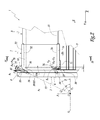
- the housing is fitted. 7 around the end 53, as represented by the arrow E of the figure 3 , so as to position the bottom wall 73 of the housing facing the end face 56 of the end 53, the walls 72 and 74 of the housing opposite, respectively, of the upper wall 52 and the lower wall 54 of the end 53, and the side walls 75 of the housing facing the side walls 55 of the end 53.
- the housing 7 is immobilized in this configuration fitted on the end 53, for example by gluing by means of an adhesive product 10 , which fills the clearance between each pair of surfaces facing the housing 7 and the end 53, as shown in FIG. figure 4 .
- this bonding can be achieved by depositing the adhesive product 10 on the outer surfaces of the walls 52, 54, 56 and 55 of the end 53 prior to the fitting of the housing 7 on this end.
- the sleepers 5 equipped with their connection boxes 7 are able to be assembled reversibly with the uprights 3. It is thus possible to make changes to articles by simply removing one or more two uprights 3 with respect to the cross members 5 of the frame 1, the housings 7 remaining in place on the crosspieces 5 in the disassembled configuration of the frame.
- a method of assembling an upright 3 of the frame 1 with the crosspieces 5 of the frame 1 equipped with their connection boxes 7 comprises steps in which:
- each of the two pins 6, which are pre-assembled tightly in the two orifices 36 of the upright 3, is positioned in the housing 76 of the casing 7 of the corresponding crossmember 5.
- the ends 53 of the two crosspieces 5, in the longitudinal direction Z of the upright 3, are moved away from each other, then the two pins 6, directed along their respective inclined axes A 36 , are introduced into the housings.
- 76 corresponding, respectively of the housing 7 fixed on the top rail 5 and the housing 7 fixed on the crossbar 5 lower.
- the necessary spacing of the ends 53 of the crosspieces 5 in the direction Z is provided with a suitable value, which can be obtained even when the opposite upright 3 is already assembled with the crosspieces 5 and when the rails are mounted on the rods-smooth 9.
- the locking screw 8 is then introduced into the housing 78 of the corresponding housing 7 and the screw 8 is screwed into the housing 38 of the upright 3, so that the external thread 85 of the rod 83 co-operates with the internal tapping 39 of the housing 38.
- the screwing of the screw 8 brings the screw head 81 against the protrusion 77 of the housing 7.
- the screwing screw 8 is easy because the prior step of positioning the pins 6 pre-mounted on the upright 3 in the housings 76 of the housings 7 of the two crosspieces 5 has the housing 78 of the housing 7 of the crossbar 5 considered in correspondence with the associated housing 38 of the upright 3.
- the frame of smooth 101 according to this second embodiment, shown partially on the figure 5 , is intended to equip a not shown loom.
- the frame 101 is obtained by the assembly of two uprights 103 and two crosspieces 105, only a post 103 and a cross member 105 being visible on the figure 5 .
- the frame 101 is designed to be moved in a movement of substantially vertical oscillations by a crowd training machine.
- each upright 103 has its longitudinal axis A 103 directed in a substantially vertical direction Z of oscillation of the frame 101, while each cross member 105 has its longitudinal axis A 105 directed in a perpendicular direction X Z direction and substantially horizontal.
- each transverse profile 105 comprises a main portion 151, tubular with rectangular section, and a tab 159 for supporting a smooth support rod 109, which is attached to the support tab 159 over substantially the entire length thereof .
- the main part 151 and the support lug 159 are connected to each other at the level of a wall 154 of the main part 151 intended to be positioned facing the other cross member 105 in the assembled configuration of the frame 101, namely the lower wall 154 of the main part 151 in the case of the upper cross member 105 of the frame 101.
- connection box 107 comprises a metal body 171 of U-shaped section, a bottom wall 173 is disposed facing an end face 156 of the end 153 in the fitted configuration of the housing 107 on the end 153 and whose walls 172 and 174 forming the legs of the body 171 in U are disposed facing, respectively, an upper wall 152 and a bottom wall 154 of the end 153.
- the lower wall 174 of the body 171 is received in a notch 157 of the cross member 105, which separates the end 153 and the lug 159 and opens at the end face 156.
- the bottom wall 173 is solid and its thickness in the Y direction of the warp yarns. frame 101 is substantially equal to the thickness of the end 153 in the direction Y.
- the thickness of the bottom wall 173 in the direction Y is greater than the width of the opening 153A of the end 153.
- the housing 107 also has two metal walls 175, each welded to a side face of the body 171, which are opposite the two side walls 155 of the end 153 in the fitted configuration of the housing 107 on this end.
- the frame 101 according to this second embodiment differs from the frame 1 described above in particular that each fastener 102 connecting the frame 101 with the drawing device for the drive in vertical oscillations of the frame 101 by the training machine the crowd is fixed on a cross member 105, at a housing 107 which equips the cross section.
- each fastener 102 is fixed on one of the two housings 107 fitted to the upper cross member 105 of the frame 101.
- each casing 107 of the upper crossmember comprises threaded housings 177 formed in the upper wall 172 of the U-shaped body 171 and intended to each receive a screw 121 for fixing the fastener 102.
- the upper wall 172 of the U-shaped body 171 has a length L 172 greater than the length L 174 of the lower wall 174 of the body 171 in U.
- This attachment of each fastener 102 directly on a housing 107 makes it possible not to weaken the cross section profile 5.
- each fastener 102 of the frame 101 can be fixed to one of the two housings 107 fitted to the bottom cross member 105 of the frame.
- each fastener 102 may be integral with the corresponding housing 107.
- the immobilization of the upright 103 with respect to the crosspiece 105 equipped with the housings 107 is obtained by means of a screw 108 for locking the upright 103 against the bottom wall 173 of the housing 107.
- the locking screw 108 is received, in assembled configuration of the upright 103 with the cross member 105, in a housing 178 of the housing 107 formed in the bottom wall 173, in the vicinity of the upper wall 172, and in a threaded housing 138 of the amount 103 which communicates with the housing 178, the central axis A 178 of the housing 178 then being substantially coincidental with the central axis A 138 of the housing 138.
- the screw 108 does not pass through the end 153 it does not weaken, therefore.
- the amount 103 is pressed by the screw against the outer face of the bottom wall 173, opposite the receiving volume of the end 153 between the walls 172 and 174.
- the head 181 of the screw 108 bears against the upright 103, instead of the housing as in the first embodiment, and the rod 183 of the screw 108 is successively received in the housings 138 and 178 with an external thread 185 of the rod 183 which cooperates with an internal thread 179 of the housing 178.
- the central axes A 138 and A 178 of the housings 138 and 178 are inclined relative to the longitudinal direction X of the cross member 105 and to the direction longitudinal Z of the upright 103 in assembled configuration of the upright 103 with the crossbar 105, so that the screwing of the screw 108 in the housings 138 and 178 aligned generates a relative displacement of the upright 103 relative to the crossbar 105, in the sen s of the arrow F 3 of the figure 5 , pointing down.
- ⁇ ' is the angle delimited between the axis A 178 and the longitudinal axis A 105 of the cross member 105.
- the angle ⁇ ' is between approximately 5 ° and 85 °, preferably of the order of 45 ° .
- the frame 101 also includes a pin 106 for positioning the upright 103 with respect to the housing 107.
- the pin 106 which is cylindrical, is pre-assembled tightly in a housing 136 of the upright 103 and received, in the assembled configuration of the upright 103 with the cross member 105, in a corresponding cylindrical housing 176, which is formed in the bottom wall 173 of the housing 107 in the vicinity of the bottom wall 174 and which communicates with the housing 136.
- the central axis A 176 of the housing 176 is substantially coincident with the central axis A 136 of the housing 136 and inclined with respect to the longitudinal direction X of the cross member 105 and the longitudinal direction Z of the upright 103.
- the pin 106 inclined relative to the longitudinal axis A 103 of the upright 103 allows efficient transmission of the inertia forces between the upright 103 and the cross member 105, through the housing 107, during the training in vertical oscillations of the frame 101.
- the inclination of the screw 108 relative to the longitudinal direction X of the cross member 105 and to the longitudinal direction Z of the upright 103 in the assembled configuration of the upright 103 with the cross member 105 also allows optimum transmission of the inertia forces between the upright 103 and the cross 105 because the relative displacement of the amount 103 relative to the cross 105 in the direction of the arrow F 3 directed downwards, during the screwing of the screw 8, puts the pin 106 in contact with the bottom of the 176.
- the pin 106 then ensures a connection between the upright 103 and the housing 107, at a positioning surface S 106 which is a surface of the pin 106 or a surface of the housing 176 in contact and which comprises a generator, or main axis, A S106 .
- a positioning surface S 106 which is a surface of the pin 106 or a surface of the housing 176 in contact and which comprises a generator, or main axis, A S106 .
- the main axis A S106 is the axis of one of the outer surface of the pin 106 and the inner surface of the housing 176 which is in line contact with the other one. the outer surface of the pin 106 and the inner surface of the housing 176, this axis A S106 being parallel to the axes A 136 and A 176 .
- the angle delimited between the main axis A S106 and the longitudinal axis A 105 of the cross member 105 is noted ⁇ '.
- the angle ⁇ ' is between approximately 0 ° and 75 °, preferably of the order of 35 °. °.
- This connection provided by the pin 106 between the upright 103 and the housing 107 at the surface S 106 leads to a redistribution of the static forces resulting from the screwing of the screw 108 from the upright 103 to the bottom wall 173 of the housing 107, by reaction of the bottom of the housing 176 against the pin 106 in the direction of the arrow F 4 of the figure 5 , directed upwards.
- the relative arrangement of the positioning surface S 106 and the screw 108 promotes the engagement of the upright 103 against the housing 107 during the screwing of the screw 108. More specifically, the positioning surface S 106 and the screw 108 are included at least partially in the same angular quadrant Q defined between, on the one hand, a plane P 0 perpendicular to the longitudinal direction Z of the upright 103 and passing through the point of intersection O of the main axis A S106 with the axis A 138 -A 178 of the screw 108 and, secondly, a plane P 1 perpendicular to the longitudinal direction X of the cross member 105 and passing through the point of intersection O, supra.
- the frame 101 is made, as in the first embodiment, by gripping and immobilizing, for example by gluing, a housing of connection 107 around each of the two ends 153 of each crossbar 105.
- the crosspieces 105 equipped with their housings 107 are then able to be assembled reversibly with the uprights 103.
- the assembly of an amount 103 of the frame 101 with the crosspieces 105 of the frame 101 equipped with their connection boxes 107 is made, similarly to the first embodiment, by positioning each of the two pins 106, which are pre-mounted in the two orifices 136 of the upright 103, in the housing 176 of the housing 107 of the corresponding cross member 105.
- the ends 153 of the two crosspieces 105, in the longitudinal direction Z of the upright 103 are brought closer to each other, then the two pins 106, directed along their respective inclined axes A 136 , are introduced into the housings.
- a locking screw 108 is then inserted into each housing 138 of the upright 103 and the screw 108 is screwed into the housing 178 of the housing 107 of the corresponding cross member 105, so that the external thread 185 of the rod 183 co-operates with the tapping. internal 179 of the housing 178.
- the screwing screw 108 brings the screw head 181 in support against the amount 103.
- the frame of rails 201 partially represented on the figure 6 is intended to equip a not shown loom and is obtained by the assembly of two uprights 203 and two crossbars 205, which have similar structures to the uprights 3 and crosses 5 of the frame 1 of the first embodiment.
- the frame 201 is provided to be moved in a movement of substantially vertical oscillations by a shedding machine and, in the use of the frame 201, each amount 203 has its axis. longitudinal A 203 directed in a substantially vertical Z direction of oscillation of the frame 201, while each cross member 205 has its longitudinal axis A 205 directed in a direction X perpendicular to the direction Z and substantially horizontal.
- the assembly means of the upright 203 with the crossmember 205 comprise a connection box 207, similar to the casing 7 of the first embodiment, fitted and fixed, for example by gluing, around the end 253 of a main portion 251. crossbar 205 which is adjacent to the amount 203.
- the connection box 207 comprises a metal body 271 with a U-shaped section, a bottom wall 273 of which is disposed facing an end face 256 of the end 253 in a fitted configuration of the housing 207 on the end 253 and whose 272 and 274 walls forming the legs of the body 271 U are disposed facing, respectively, an upper wall 252 and a bottom wall 254 of the end 253.
- the bottom wall 274 of the body 271 is received in a notch 257 of the cross member 205, which separates the end 253 and a support lug 259 of the crossmember 205 on which is fixed a hanger rod 209.
- the thickness of the bottom wall 273 in the Y direction of the warp yarns of the frame 201 is substantially equal to the thickness of the end 253 in the direction Y, so that the thickness of the bottom wall 273 in the Y direction is also greater than the width of the opening 253A of the end 253.
- the case 207 also comprises two metal walls, each welded to a side face of the body 271, which are opposite the two side walls of the end 253 in the fitted configuration of the housing 207 on this end.
- the frame 201 differs from the frame 1 of the first embodiment in that the amount 203 comprises an upper recess 231 adapted to receive, by complementary shapes, a projecting portion 273A of the bottom wall 273 of the housing 207.
- L recess 231 is delimited in its lower part, that is to say near the bottom wall 274 of the housing 207 when the portion 273A is received in the recess 231, by a ramp 236 for positioning the upright 203 relative to 207.
- the ramp 236 is adapted to cooperate with a corresponding ramp 276, defined by the portion 273A of the housing 207.
- the guide axis A 236 of the ramp 236, taken in parallel in the middle plane of the frame 201, is substantially coincident with a director axis A 276 of the ramp 276, also taken parallel to the average plane of the frame 201, and inclined with respect to the longitudinal direction X of the cross member 205 and the longitudinal direction Z of the amount 203.
- the immobilization of the upright 203 relative to the cross member 205 is obtained by means of a locking screw 208, which is received, in assembled configuration of the upright 203 with the cross member 205, in a housing 278 of the housing 207, formed in a protrusion 277 of the bottom wall 273 in the vicinity of the upper wall 272 of the body 271, and in a threaded housing 238 of the upright 203 which communicates with the housing 278.
- the screw 208 does not cross the end 253 and plate the amount 203 against the outer face of the bottom wall 273.
- the central axis A 278 of the housing 278 is substantially coincident with the central axis A 238 of the housing 238, the head of the screw 208 bearing against the protrusion 277.
- the central axes A 238 and A 278 of the housings 238 and 278 are inclined relative to the longitudinal direction X of the crossmember 205 and to the longitudinal direction Z of the amount 203 in accordance with assembled iguration of the amount 203 with the cross 205, so that during the screwing of the screw 208 in the housings 238 and 278 aligned, a relative displacement of the amount 203 relative to the cross 205 is generated in the direction of the arrow F 5 of the figure 6 , directed upwards.
- the cooperation between the ramps 236 and 276, inclined relative to the longitudinal axis A 203 of the amount 203 allows an effective transmission of the inertia forces between the amount 203 and the cross member 205, by through the housing 207, during the drive in vertical oscillations of the frame 201.
- the relative displacement of the upright 203 relative to the crossmember 205 in the direction of the arrow F 5 directed upwards, during the screwing of the screw 208, plate the positioning ramp 236 of the amount 203 in contact with the ramp 276 of the housing 207.
- the positioning ramp 236 then provides a connection between the post 203 and the housing 207, at a positioning surface S 236 which is a surface of the ramp 236 or a surface of the ramp 276 in contact and which comprises a main axis, namely the director axis A 236 236.
- the angle delimited between the longitudinal axis A 205 of the crossmember 205 and the principal axis A 236 is defined: the angle ⁇ "is between approximately 0 ° and 75 °, preferably the order of 35 °.
- the relative arrangement of the positioning surface S 236 and the screw 208 namely the fact that the positioning surface S 236 and the screw 208 are included in the same angular quadrant Q defined between, on the one hand, a plane P 0 perpendicular to the longitudinal direction Z of the upright 203 and passing through the intersection point O of the main axis A 236 with the axis A 238 -A 278 of the screw 208 and, secondly, a plane P 1 perpendicular to the longitudinal direction X of the cross member 205 and passing through the intersection point O above, promotes the engagement of the amount 203 against the housing 207 during screwing of the screw 208.
- the cross sections 5, 105, 205 of a heald frame 1, 101, 201 according to the invention are not subject to static forces blocking amounts in configuration assembly of the frame, thanks to the presence of a connection box 7, 107, 207 which is fixed on each crossbeam in its assembly area with an amount and which cashes all the static forces resulting from the locking of the amount relative to at the cross.
- This advantage is valid even if the locking member and / or the positioning surface is not inclined with respect to the direction X or the direction Z.
- the static forces resulting from the blocking of the upright relative to the cross member are concealed by the bottom wall of the housing 7, 107, 207, in the part of this wall situated between the contact zone between the bottom wall and the wall.
- locking member in particular the locking screw in the preceding examples, and the contact zone between the bottom wall and the positioning member, in particular the pin or the positioning ramp in the preceding examples, this wall of background being continuous, massive and very resistant.
- each cross section of a frame according to the invention can have a width, in the Y direction, larger than the width of the cross sections of the frames of the state of the art, and therefore have an increased resistance in bending.
- the U-section body of the connection box 7, 107, 207 fixed around each end of a cross member of a heald frame according to the invention contributes to an efficient transmission of inertia forces between the housing connection and the cross section, when driving in vertical oscillations of the frame.
- the inertial forces are transmitted alternately between the upper wall of the body. U and the upper wall of the crossbar and between the bottom wall of the U-shaped body and the bottom wall of the crossbar.
- the relative arrangement of the positioning surface and the locking member of a frame according to the invention and more specifically the fact that the positioning surface and the locking member are included at least partially in the same angular quadrant defined between, on the one hand, a plane P 0 perpendicular to the longitudinal direction Z of the upright and passing through the point of intersection O of the main axis of the positioning surface with the axis of the locking member and, secondly, a plane P 1 perpendicular to the longitudinal direction X of the cross member and passing through the point of intersection O, promotes the coming into contact of the upright against the bottom wall of the housing 7, 107 , 207 during screwing.
- each assembly area of an upright and a cross member also makes it possible to ensure accurate positioning of the crossbar relative to the amount in the Y direction of the warp yarns, which limits the risk of attachment of a frame according to the invention with neighboring frames, and a precise relative positioning of the two cross members of the frame in the vertical direction Z, which ensures a controlled separation of the two carrier rods 9 , 109, 209 after blocking the amounts.
- the openings 53A, 153A, 253A of the two ends of each crossbar of a frame 1, 101, 201 according to the invention are generally closed by the bottom walls of the two connection boxes 7, 107, 207 fitted to the cross member. and reinforced by the solid U-shaped body and the side walls of the housings, these housings being designed to remain in place on the crosspiece in disassembled configuration of the amounts relative to the cross.
- the cross is thus protected against any damage or pollution that may alter the structure of the cross at its ends.
- each connection box 7, 107, 207 of a cross member of a frame according to the invention which is formed by a U-section body closed laterally by two side walls, can be replaced by an element of connection formed by a simple U-section body, without side walls, this U-section connection element being fitted and fixed around the end of the cross-member.
- the thickness, in the Y direction of the warp yarns, of the wall of bottom of such a U-section connection element devoid of side walls is preferably equal to or greater than the width, in the Y direction, of each end opening of the crossbar, so that the bottom wall is adapted to close this opening.
- connection box 7, 107, 207 with side walls 75, 175, 275 as shown in the figures, one of the side walls of the housing may also extend along the support leg of the housing. crosses, as shown in dotted lines on the figure 4 , so as to create an additional bonding interface between the housing and the cross member.
- the bottom wall 73, 173, 273 of the connection box may also have a thickness, in the Y direction of the warp yarns, greater than the thickness, in the Y direction, of the end 53, 153, 253 of the cross member. .
- each positioning pin 6, 106 can indifferently be preassembled tightly in the housing 36, 136 of the upright or in the housing 76, 176 of the connection box 7, 107, prior to the assembly of the uprights and crosspieces.
- the housing 76, 176 for receiving the pin 6, 106 in the housing 7, 107 may also be non-opening on the side of the cross section 5, 105.
- 101 is greater than the width of the opening 53A, 153A end of the cross member in the Y direction, the housing 7, 107 closes the end of the crossbar in assembled configuration of the frame.
- the end of the cross is also closed in disassembled configuration of the amount relative to the cross.
- the number of locking members associated with each connection element 7, 107, 207 may also be greater than one.
- Fixing the fasteners 2, 102 connecting the frame with the pulling device can also be carried out indifferently on the casings 7, 107 for connecting the sleepers or on the uprights, regardless of the angular quadrant Q, delimited between the planes P 0 and P 1 defined above, wherein are included the positioning surface and the locking member.
- the connection clips 2, 102 can in particular be fixed to the connection boxes with the arrangement of the positioning surface and the locking member shown in the first embodiment, or on the uprights with the arrangement of the positioning surface and the locking member shown in the second embodiment of FIG. production.
- connection boxes 7, 107, 207 in which the angle ⁇ , ⁇ ', ⁇ "of inclination of the main axis of the positioning surface S 6 , S 106 , S 236 with respect to the longitudinal axis of the cross member is less than the angle ⁇ , ⁇ ', ⁇ "of inclination of the axis of the locking member 8, 108, 208 with respect to the longitudinal axis from the transom.
- a redistribution of static blocking forces from the upright to the housing 7, 107, 207 is obtained as soon as the locking member is inclined relative to the support surface of the upright against the housing and that the positioning cooperates with the housing at the level of the positioning surface.
- the value of the angle ⁇ , ⁇ ', ⁇ may be greater than the value of the angle ⁇ , ⁇ ', ⁇ ".
- the invention has been described for relative arrangements of the positioning member and the locking member in which the main axis of the positioning surface S 6 , S 106 , S 236 and the axis of the locking member 8, 108, 208 are parallel to the mean plane ⁇ of the frame 1, 101, 201.
- these axes may not be parallel to the plane ⁇ .
- the angles of inclination ⁇ , ⁇ ', ⁇ "and ⁇ , ⁇ ', ⁇ " are defined between the longitudinal direction X of the cross member 5, 105, 205 and the orthogonal projection on the plane ⁇ respectively of the axis of the locking member and the main axis of the positioning surface.
- the criterion to respect for the advantageous relative arrangement of the positioning surface and the locking member of a frame according to the invention is that, in assembled configuration of the amount with the cross member, the locking member and the positioning surface are included at least partially in the same angular quadrant Q defined between, on the one hand, a plane P 0 perpendicular to the longitudinal direction Z of the upright and passing through the point of intersection O of the orthogonal projections of the axis of the blocking member and the main axis of the positioning surface on the mean plane ⁇ of the frame and, secondly, a plane P 1 perpendicular to the longitudinal direction X of the cross member and passing through the point d
- the advantageous relative arrangement of the surface of positioning and the locking member of a frame according to the invention is such that the angle, oriented in the trigonometric direction and taken from the axis A 0 defined above until the orthogonal projection of the axis of the locking member on the medium plane ⁇ of the frame, and the angle, oriented in the trigonometric direction and taken
- connection box of a heald frame according to the invention can be implemented on any type of cross section, including a cross section made of aluminum, steel, composite material, or other.
- the geometry of the cross sections of a heald frame according to the invention, which receive the connection boxes, may also be different from that described above.
- the main portion 51, 151, 251 of the crossmember may have a cross section I.
- the carrier rod 9, 109, 209 may also be connected to the cross member by means other than a support bracket of the crossing.
Landscapes
- Engineering & Computer Science (AREA)
- Textile Engineering (AREA)
- Looms (AREA)
Applications Claiming Priority (1)
| Application Number | Priority Date | Filing Date | Title |
|---|---|---|---|
| FR0759788A FR2925073B1 (fr) | 2007-12-12 | 2007-12-12 | Cadre de lisses pour metier a tisser equipe d'un tel cadre. |
Publications (2)
| Publication Number | Publication Date |
|---|---|
| EP2071065A1 true EP2071065A1 (de) | 2009-06-17 |
| EP2071065B1 EP2071065B1 (de) | 2012-02-08 |
Family
ID=39590943
Family Applications (1)
| Application Number | Title | Priority Date | Filing Date |
|---|---|---|---|
| EP20080171294 Active EP2071065B1 (de) | 2007-12-12 | 2008-12-11 | Weblitzenrahmen für Webrahmen und mit diesem Litzenrahmen ausgestatteter Webrahmen |
Country Status (4)
| Country | Link |
|---|---|
| EP (1) | EP2071065B1 (de) |
| JP (1) | JP2009161897A (de) |
| CN (1) | CN101457431B (de) |
| FR (1) | FR2925073B1 (de) |
Families Citing this family (1)
| Publication number | Priority date | Publication date | Assignee | Title |
|---|---|---|---|---|
| CN117780771B (zh) * | 2022-09-21 | 2025-10-10 | 荣耀终端股份有限公司 | 转轴装置以及折叠屏设备 |
Citations (4)
| Publication number | Priority date | Publication date | Assignee | Title |
|---|---|---|---|---|
| DE548200C (de) * | 1930-04-06 | 1932-04-15 | Remy Wilms | Webschaft |
| US1922922A (en) | 1932-01-26 | 1933-08-15 | Andrews Isaac | Heddle frame construction |
| FR2137643A1 (de) * | 1971-05-13 | 1972-12-29 | Grob & Co Ag | |
| WO2004027134A2 (fr) * | 2002-09-17 | 2004-04-01 | Staubli Faverges | Cadre de lisses et metier a tisser equipe d'un tel cadre |
Family Cites Families (2)
| Publication number | Priority date | Publication date | Assignee | Title |
|---|---|---|---|---|
| DE4038384A1 (de) * | 1990-12-01 | 1992-06-04 | Grob & Co Ag | Webschaft mit loesbaren eckverbindungen |
| CN2421293Y (zh) * | 2000-04-19 | 2001-02-28 | 上海纺织综架厂 | 一种用于织机综框的连接结构 |
-
2007
- 2007-12-12 FR FR0759788A patent/FR2925073B1/fr not_active Expired - Fee Related
-
2008
- 2008-12-11 JP JP2008315346A patent/JP2009161897A/ja not_active Withdrawn
- 2008-12-11 EP EP20080171294 patent/EP2071065B1/de active Active
- 2008-12-12 CN CN2008101840307A patent/CN101457431B/zh active Active
Patent Citations (5)
| Publication number | Priority date | Publication date | Assignee | Title |
|---|---|---|---|---|
| DE548200C (de) * | 1930-04-06 | 1932-04-15 | Remy Wilms | Webschaft |
| US1922922A (en) | 1932-01-26 | 1933-08-15 | Andrews Isaac | Heddle frame construction |
| FR2137643A1 (de) * | 1971-05-13 | 1972-12-29 | Grob & Co Ag | |
| WO2004027134A2 (fr) * | 2002-09-17 | 2004-04-01 | Staubli Faverges | Cadre de lisses et metier a tisser equipe d'un tel cadre |
| EP1540056B1 (de) | 2002-09-17 | 2007-04-25 | Stäubli Faverges | Webschaft und damit ausgerüstete webmaschine |
Non-Patent Citations (1)
| Title |
|---|
| "ALFORFIX: LE NOUVEAU CADRE HAUTE RESISTANCE DE GROB//", INDUSTRIE TEXTILE, STE SIPPE SARL, METZ, FR, no. 1346, 1 November 2002 (2002-11-01), pages 65, XP001167680, ISSN: 0019-9176 * |
Also Published As
| Publication number | Publication date |
|---|---|
| FR2925073A1 (fr) | 2009-06-19 |
| EP2071065B1 (de) | 2012-02-08 |
| JP2009161897A (ja) | 2009-07-23 |
| CN101457431B (zh) | 2012-09-05 |
| CN101457431A (zh) | 2009-06-17 |
| FR2925073B1 (fr) | 2010-04-09 |
Similar Documents
| Publication | Publication Date | Title |
|---|---|---|
| EP0586320A1 (de) | System zum Befestigen eines Versteifungselementes einer Vorhangfassade an einem Konstruktionselement | |
| EP0442830A1 (de) | Leitplanke | |
| EP0368778A1 (de) | Zaun aus geschweissten Drahtgitter | |
| FR2549795A1 (fr) | Chassis pour vehicule de petites dimensions | |
| FR3027313A1 (fr) | Lisse pour metier a tisser, metier a tisser equipe d'une telle lisse et procede de fabrication d'une telle lisse | |
| EP2071065B1 (de) | Weblitzenrahmen für Webrahmen und mit diesem Litzenrahmen ausgestatteter Webrahmen | |
| EP3009545B1 (de) | Litze für webmaschinen, und mit dieser litze ausgestattete webmaschine | |
| EP1065771B1 (de) | Sprosse oder Holm für Kabelleiter, Kabelleiter und Montageverfahren | |
| EP1540056B1 (de) | Webschaft und damit ausgerüstete webmaschine | |
| EP3009543B1 (de) | Litze für webrahmen, und mit dieser litze ausgestatteter webrahmen | |
| EP2009158B1 (de) | Bremsvorrichtung, Weblitzenrahmen, der mit einer solchen Bremsvorrichtung ausgestattet ist, und Webrahmen, der mit einem solchen Litzenrahmen ausgestattet ist | |
| FR2645244A3 (fr) | Armature pour un chassis en lattes | |
| EP1967624B1 (de) | Webblatt für eine Webmaschine, Webmaschine die ein solches Webblatt umfasst und Herstellungsverfahren eines solchen Webblattes | |
| FR2527254A1 (fr) | Procede et dispositif pour l'assemblage et l'alignement de panneaux de coffrage | |
| EP1988195B1 (de) | Verbindungsstange für Zugsystem und Webrahmen, der eine solche Verbindungsstange umfasst | |
| EP1176237B1 (de) | Webschaft mit Litzendämpfungsvorrichtung für Webmaschine sowie Litzendämpfungsvorrichtung | |
| CH683351A5 (fr) | Lame de retenue. | |
| EP0533600B1 (de) | Lösbare flexible Webschaftrahmeneckverbindung für Webmaschinen | |
| WO2005010253A9 (fr) | Cadre de lisses et metier a tisser equipe d'au moins un tel cadre | |
| EP1830073A1 (de) | Vorrichtung zum Befestigen von zwei aneinanderliegenden Teilen mittels einer Klammer | |
| FR2912476A3 (fr) | Piece d'assemblage pour elements longiformes,et procede de fabrication de cette piece d'assemblage | |
| WO2017098103A1 (fr) | Essieu arrière de véhicule automobile comportant des moyens de retenue pour améliorer la liaison par collage d'une traverse en matériau composite avec les bras | |
| EP4118721B1 (de) | Kabelführungslänge mit einem fischplattierten ende | |
| FR2766783A1 (fr) | Structure de caisse de vehicule automobile comportant des moyens d'assemblage perfectionnes | |
| FR2849067A1 (fr) | Lisse, cadre de lisses et metier a tisser equipe d'un tel cadre |
Legal Events
| Date | Code | Title | Description |
|---|---|---|---|
| PUAI | Public reference made under article 153(3) epc to a published international application that has entered the european phase |
Free format text: ORIGINAL CODE: 0009012 |
|
| AK | Designated contracting states |
Kind code of ref document: A1 Designated state(s): AT BE BG CH CY CZ DE DK EE ES FI FR GB GR HR HU IE IS IT LI LT LU LV MC MT NL NO PL PT RO SE SI SK TR |
|
| AX | Request for extension of the european patent |
Extension state: AL BA MK RS |
|
| 17P | Request for examination filed |
Effective date: 20091202 |
|
| AKX | Designation fees paid |
Designated state(s): BE DE FR IT TR |
|
| GRAP | Despatch of communication of intention to grant a patent |
Free format text: ORIGINAL CODE: EPIDOSNIGR1 |
|
| GRAS | Grant fee paid |
Free format text: ORIGINAL CODE: EPIDOSNIGR3 |
|
| GRAA | (expected) grant |
Free format text: ORIGINAL CODE: 0009210 |
|
| AK | Designated contracting states |
Kind code of ref document: B1 Designated state(s): BE DE FR IT TR |
|
| REG | Reference to a national code |
Ref country code: DE Ref legal event code: R096 Ref document number: 602008013213 Country of ref document: DE Effective date: 20120405 |
|
| PLBE | No opposition filed within time limit |
Free format text: ORIGINAL CODE: 0009261 |
|
| STAA | Information on the status of an ep patent application or granted ep patent |
Free format text: STATUS: NO OPPOSITION FILED WITHIN TIME LIMIT |
|
| 26N | No opposition filed |
Effective date: 20121109 |
|
| REG | Reference to a national code |
Ref country code: DE Ref legal event code: R097 Ref document number: 602008013213 Country of ref document: DE Effective date: 20121109 |
|
| REG | Reference to a national code |
Ref country code: FR Ref legal event code: PLFP Year of fee payment: 8 |
|
| REG | Reference to a national code |
Ref country code: FR Ref legal event code: PLFP Year of fee payment: 9 |
|
| PG25 | Lapsed in a contracting state [announced via postgrant information from national office to epo] |
Ref country code: IT Free format text: LAPSE BECAUSE OF NON-PAYMENT OF DUE FEES Effective date: 20151211 |
|
| PG25 | Lapsed in a contracting state [announced via postgrant information from national office to epo] |
Ref country code: IT Free format text: LAPSE BECAUSE OF NON-PAYMENT OF DUE FEES Effective date: 20151211 |
|
| PGRI | Patent reinstated in contracting state [announced from national office to epo] |
Ref country code: IT Effective date: 20170710 |
|
| REG | Reference to a national code |
Ref country code: FR Ref legal event code: PLFP Year of fee payment: 10 |
|
| PGFP | Annual fee paid to national office [announced via postgrant information from national office to epo] |
Ref country code: FR Payment date: 20201227 Year of fee payment: 13 |
|
| PG25 | Lapsed in a contracting state [announced via postgrant information from national office to epo] |
Ref country code: FR Free format text: LAPSE BECAUSE OF NON-PAYMENT OF DUE FEES Effective date: 20211231 |
|
| PGFP | Annual fee paid to national office [announced via postgrant information from national office to epo] |
Ref country code: IT Payment date: 20251219 Year of fee payment: 18 |
|
| PGFP | Annual fee paid to national office [announced via postgrant information from national office to epo] |
Ref country code: BE Payment date: 20251229 Year of fee payment: 18 Ref country code: TR Payment date: 20251121 Year of fee payment: 18 |
|
| PGFP | Annual fee paid to national office [announced via postgrant information from national office to epo] |
Ref country code: DE Payment date: 20251229 Year of fee payment: 18 |