EP2071065B1 - Weblitzenrahmen für Webrahmen und mit diesem Litzenrahmen ausgestatteter Webrahmen - Google Patents
Weblitzenrahmen für Webrahmen und mit diesem Litzenrahmen ausgestatteter Webrahmen Download PDFInfo
- Publication number
- EP2071065B1 EP2071065B1 EP20080171294 EP08171294A EP2071065B1 EP 2071065 B1 EP2071065 B1 EP 2071065B1 EP 20080171294 EP20080171294 EP 20080171294 EP 08171294 A EP08171294 A EP 08171294A EP 2071065 B1 EP2071065 B1 EP 2071065B1
- Authority
- EP
- European Patent Office
- Prior art keywords
- upright
- crossmember
- housing
- frame
- configuration
- Prior art date
- Legal status (The legal status is an assumption and is not a legal conclusion. Google has not performed a legal analysis and makes no representation as to the accuracy of the status listed.)
- Active
Links
Images


Classifications
-
- D—TEXTILES; PAPER
- D03—WEAVING
- D03C—SHEDDING MECHANISMS; PATTERN CARDS OR CHAINS; PUNCHING OF CARDS; DESIGNING PATTERNS
- D03C9/00—Healds; Heald frames
- D03C9/06—Heald frames
- D03C9/0666—Connection of frame parts
- D03C9/0675—Corner connections between horizontal rods and side stays
Definitions
- EP-B-1,540,056 discloses a heald frame in which the assembly of an upright and a cross is obtained through means of locking the amount relative to the crossbar which are disposed within one end of the cross.
- the end of the cross member is reinforced externally by a metal band.
- significant static forces are applied to the cross member immobilized configuration of the amount relative to the end of the crossbar, which weakens the structure of the frame.
- the invention intends to remedy more particularly by proposing a robust heald frame, the structure of which is not weakened during the assembly of its uprights and its constituent webs or during their relative disassembly. .
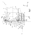
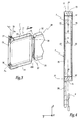
- Each amount 3 of the frame 1 is a substantially straight aluminum profile. As shown on the figure 1 , each upright 3 is equipped in its lower part with a fastener 2 intended to be connected, by a not shown pulling device, to the shed-forming machine, for driving in vertical oscillations of the frame 1.
- the thickness e 7 of the bottom wall 73 in the Y direction of the warp yarns of the frame 1 is substantially equal to the thickness e 5 of the end 53 in the Y direction.
- the thickness e 7 is greater than the width l 5 of the opening 53A of the end 53.
- the casing 7 also comprises two opposite metal walls 75, each welded to a lateral face of the body 71, which laterally close the U-shaped section of the body 71 and which face the two lateral walls 55 of the end 53 in an interlocked configuration. of the body 71 on this end.
- the housing 7 thus defines an interior receiving volume of the end 53, the end 53 being substantially complementary, to the assembly clearance, the internal volume of the housing 7.
- the end face 56 of the end 53 is machined so as to be recessed, along the longitudinal direction X of the crosspiece 5, by a length L with respect to the end face 58 of the end of the support lug 59.
- the fitting of the housing 7 around the end 53 does not penalize the useful length of the carrier rod 9.
- the casing 7 is fixed in a configuration fitted around the end 53 of the crosspiece 5 by gluing, by means of an adhesive product 10.
- Such a bonding attachment makes it possible to adjust the position of the casing 7 relative to the end 53 in the longitudinal direction X of the crossbar 5. This results in the possibility of obtaining a very precise frame length.
- the bonding attachment makes it possible not to weaken the cross section 5.
- the fixing of the housing 7 on the end 53 can be obtained by any other appropriate means, for example by screwing or riveting.
- the locking screw 8 is then introduced into the housing 78 of the corresponding housing 7 and the screw 8 is screwed into the housing 38 of the upright 3, so that the external thread 85 of the rod 83 co-operates with the internal tapping 39 of the housing 38.
- the screwing of the screw 8 brings the screw head 81 against the protrusion 77 of the housing 7.
- the screwing screw 8 is easy because the prior step of positioning the pins 6 pre-mounted on the upright 3 in the housings 76 of the housings 7 of the two crosspieces 5 has the housing 78 of the housing 7 of the crossbar 5 considered in correspondence with the associated housing 38 of the upright 3.
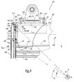
- each upright 103 has its longitudinal axis A 103 directed in a substantially vertical direction Z of oscillation of the frame 101, while each cross member 105 has its longitudinal axis A 105 directed in a perpendicular direction X Z direction and substantially horizontal.
- the end of the cross is also closed in disassembled configuration of the amount relative to the cross.
- the number of locking members associated with each connection element 7, 107, 207 may also be greater than one.
- Fixing the fasteners 2, 102 connecting the frame with the pulling device can also be carried out indifferently on the casings 7, 107 for connecting the sleepers or on the uprights, regardless of the angular quadrant Q, delimited between the planes P 0 and P 1 defined above, wherein are included the positioning surface and the locking member.
- the connection clips 2, 102 can in particular be fixed to the connection boxes with the arrangement of the positioning surface and the locking member shown in the first embodiment, or on the uprights with the arrangement of the positioning surface and the locking member shown in the second embodiment of FIG. production.
- connection boxes 7, 107, 207 in which the angle ⁇ , ⁇ ', ⁇ "of inclination of the main axis of the positioning surface S 6 , S 106 , S 236 with respect to the longitudinal axis of the cross member is less than the angle ⁇ , ⁇ ', ⁇ "of inclination of the axis of the locking member 8, 108, 208 with respect to the longitudinal axis from the transom.
- a redistribution of static blocking forces from the upright to the housing 7, 107, 207 is obtained as soon as the locking member is inclined relative to the support surface of the upright against the housing and that the positioning cooperates with the housing at the level of the positioning surface.
- the value of the angle ⁇ , ⁇ ', ⁇ may be greater than the value of the angle ⁇ , ⁇ ', ⁇ ".
- the criterion to respect for the advantageous relative arrangement of the positioning surface and the locking member of a frame according to the invention is that, in assembled configuration of the amount with the cross member, the locking member and the positioning surface are included at least partially in the same angular quadrant Q defined between, on the one hand, a plane P 0 perpendicular to the longitudinal direction Z of the upright and passing through the point of intersection O of the orthogonal projections of the axis of the blocking member and the main axis of the positioning surface on the mean plane ⁇ of the frame and, secondly, a plane P 1 perpendicular to the longitudinal direction X of the cross member and passing through the point d
- the advantageous relative arrangement of the surface of positioning and the locking member of a frame according to the invention is such that the angle, oriented in the trigonometric direction and taken from the axis A 0 defined above until the orthogonal projection of the axis of the locking member on the medium plane ⁇ of the frame, and the angle, oriented in the trigonometric direction and taken
Landscapes
- Engineering & Computer Science (AREA)
- Textile Engineering (AREA)
- Looms (AREA)
Claims (15)
- Schaftrahmen (1; 101; 201) für eine Webmaschine, wobei dieser Rahmen durch das Zusammenfügen von zwei Pfosten (3; 103; 203) und zwei Traversen (5; 105; 205) erhalten wird, wobei mindestens ein Ende (53; 153; 253) mindestens einer Traverse (5; 105; 205) mit Mitteln (7, 8; 107, 108; 207, 208) zum Zusammenfügen der Traverse (5; 105; 205) und eines Pfostens (3; 103; 203) ausgerüstet ist und die Mittel (7, 8; 107, 108; 207, 208) zum zusammenfügen ein Verbindungselement (7; 107; 207) aufweisen, das einen Körper (71; 171; 271) mit U-förmigem Querschnitt, der um das Ende (53; 153; 253) der Traverse (5; 105; 205) befestigt ist, und ein Organ (8; 108; 208) zur Blockierung des Pfostens (3; 103; 203) in Bezug auf das Verbindungselement (7; 107; 207) umfasst, wobei der Körper (71; 171; 271) mit U-förmigem Querschnitt um das Ende (53; 153; 253) der Travers (5; 105; 205) herum mit der Bodenwand (73; 173; 273) des U, die gegenüberliegend zur Endfläche (56; 156; 256) des Endes (53; 153; 253) angeordnet ist, und mit Wänden (72, 74; 172, 174; 272, 274), die die Schenkel des U bilden und gegenüberliegend zu der oberen und unteren Wand (52, 54; 152, 154; 252, 254) des Endes (53; 153; 253) angeordnet sind, befestigt ist, dadurch gekennzeichnet, dass der Pfosten (3; 103; 203) durch das Blockierorgan (8; 108; 208) in Auflage gegen die Bodenwand (73; 173; 273) des Körpers (71; 171; 271) mit U-förmigem Querschnitt des Verbindungselements (7; 107; 207) festgelegt ist.
- Schaftrahmen nach Anspruch 1, dadurch gekennzeichnet, dass das Blockierorgan (8; 108; 208) teilweise in dem Körper (71, 171; 271) mit U-förmigem Querschnitt des Verbindungselements (7; 107; 207) in zusammengesetztem Zustand des Pfostens (3; k103; 203) und der Traverse (5; 105; 205) aufgenommen ist.
- Schaftrahmen nach Anspruch 2, dadurch gekennzeichnet, dass das Verbindungselement (7; 107; 207) einen Raum (78; 178; 278) zur Aufnahme des Blockierorgans (8; 108; 208) aufweist, der im zusammengefügten Zustand des Pfostens (3; 103; 203) und der Traverse (5; 105; 205) mit einem Raum (38; 138; 238) zur Aufnahme des Blockierorgans (8; 108; 208), der in dem Pfosten (3; 103; 203) angeordnet ist, in Verbindung steht, wobei die Aufnahmeräume (38, 78; 138, 178; 238, 278) des Blockierorgans (8; 108; 208) auf eine Achse (A38, A78; A138, A178; A238, A278), die in Bezug auf eine Längsrichtung (X) der Traverse (5; 105; 205) und eine Längsrichtung (Z) des Pfostens (3; 103; 203) im zusammengefügten Zustand des Pfostens (3; 103; 203) und der Traverse (5; 105; 205) geneigt ist.
- Schaftrahmen nach Anspruch 3, dadurch gekennzeichnet, dass das Blockierorgan eine Schraube (8; 108; 208) ist, wobei mindestens einer der Aufnahmeräume (38, 78; 138, 178; 238, 278) der Schraube (8; 108; 208) mit einem Innengewinde (39; 179) versehen ist.
- Schaftrahmen nach einem beliebigen der vorhergehenden Ansprüche, dadurch gekennzeichnet, dass die Traverse (5; 105; 205) einen Hauptbereich (51; 151; 251) und einen Bereich (59; 159; 259) zum Halten einer Litzenträgerleiste (9; 109; 209) aufweist, wobei der Körper (71; 171; 271) mit U-förmigem Querschnitt um das Ende (53; 153; 253) des Hauptbereichs (51; 151; 251) aufgesetzt ist, wobei der Hauptbereich (51; 151; 251) und der Haltebereich (59; 159; 259) voneinander benachbart zum Ende (53; 153; 253) durch ein Volumen (57; 157; 257) zur Aufnahme einer Wand (74; 174; 274) getrennt sind, die einen Schenkel des Körpers (71; 171; 271) mit U-förmigem Querschnitt im aufgesetzten Zustand des Körpers (71; 171; 271) um den Hauptbereich (51; 151; 251) herum bildet.
- Schaftrahmen nach einem beliebigen der vorhergehenden Ansprüche, dadurch gekennzeichnet, dass die Bodenwand (73; 173; 273) des Körpers (71; 171; 271) mit U-förmigem Querschnitt, der an dem Ende (53; 153; 253) der Traverse (5; 105; 205) befestigt ist, eine Dicke (e7) gemäß der Richtung (Y) der Kettfäden des Rahmens (1; 101; 201) mindestens gleich der Breite (l5) einer Öffnung (53A; 153A; 253A) des Endes der Traverse (5; 105; 205) gemäß der Richtung (Y) der Kettfäden aufweist.
- Schaftrahmen nach einem beliebigen der vorhergehenden Ansprüche, dadurch gekennzeichnet, dass er außerdem ein Organ (6; 106; 236) zur Positionierung des Pfostens (3; 103; 203) in Bezug auf das Verbindungselement (7; 107; 207) aufweist, wobei das Positionierorgan (6; 106; 236 geeignet ist, im zusammengefügten Zustand des Pfostens (3; 103; 203) und der Traverse (5; 105; 205) eine Verbindung zwischen dem Pfosten (3; 103; 203) und dem Verbindungselement (7; 107; 207) an einer Positionierfläche (S6; S106; S236) sicherzustellen, wobei die Positionierfläche (S6; S106; S236) eine Hauptachse (AS6; AS106; A236) umfasst, die in Bezug auf eine Längsrichtung (Z) des Pfostens (3; 103; 203) geneigt ist.
- Schaftrahmen nach Anspruch 7, dadurch gekennzeichnet, dass im zusammengesetzten Zustand des Pfostens (3; 103; 203) und der Traverse (5; 105; 205) das Blockierorgan (8; 108; 208) und die Positionierfläche (S6; S100; S236) zumindest teilweise in einem selben Winkelquadrant (Q) umfasst sind, der einerseits zwischen einer Ebene (P0), die senkrecht zur Längsrichtung (Z) des Pfostens (3; 103; 203) liegt und durch den Schnittpunkt (O) der orthogonalen Projektionen der Achse (A38, A78; A138, A178; A238, A278 des Blockierorgans (8; 108; 208) und der Hauptachse (AS6; AS106; A236) der Positionierfläche (S6; S106; S236) auf die Mittelebene (π) des Rahmens (1; 101; 201) hindurchgeht, und andererseits einer Ebene (P1), die senkrecht zur Längsrichtung (X) der Traverse (5; 105; 205)liegt und durch den Schnittpunkt (O) hindurchgeht, definiert ist.
- Schaftrahmen nach einem beliebigen der Ansprüche 7 oder 8, dadurch gekennzeichnet, dass im zusammengefügten Zustand des Pfostens (3; 103; 203) und der Traverse (5; 105; 205) der Winkel (α; α'; α") der Neigung der orthogonalen Projektion der Achse (A38, A78; A138, A178; A238, A278) des Blockierorgans (8; 108; 208) auf die Mittelebene (π) des Rahmens (1; 101; 201) in Bezug auf die Längsrichtung (X) der Traverse (5; 105; 205) größer als der Winkel (β; β'; β") der Neigung der orthogonalen Projektion der Hauptachse (AS6; AS106; A236) der Positionierfläche (S6; S106; S236) auf die Mittelebene (π) des Rahmens (1; 101; 201) in Bezug auf die Längsrichtung (X) der Traverse (5; 105; 205) ist.
- Schaftrahmen nach einem beliebigen der Ansprüche 7 bis 9, dadurch gekennzeichnet, dass im zusammengefügten Zustand des Pfostens (3; 103; 203) und der Traverse (5; 105; 205) das Blockierorgan (8; 108; 208) und das Positionierorgan (6; 106; 236) mit dem Verbindungselement (7; 107; 207) an der Bodenwand (73; 173; 273) des Körpers (71; 171; 271) mit U-förmigem Querschnitt zusammenwirken.
- Schaftrahmen nach einem beliebigen der Ansprüche 7 bis 10, dadurch gekennzeichnet, dass das Positionierelement ein zylindrischer Stift (6; 106) ist, der in miteinander in Verbindung stehenden Räumen (36, 76; 136, 176) des Pfostens (3; 103) und des Verbindungselements (7; 107) im zusammengefügten Zustand des Pfostens (3; 103) und der Traverse (5; 105) aufgenommen ist, wobei die Räume (36, 76; 136, 176) zur Aufnahme des Positionierorgans (6; 106) auf eine Achse (A36, A76; A136, A176) zentriert sind, die in Bezug auf eine Längsrichtung (Z) des Pfostens (3; 103) in dem zusammengefügten Zustand des Pfostens (3; 103) und der Traverse (5; 105) geneigt ist.
- Schaftrahmen nach einem beliebigen der Ansprüche 7 bis 10, dadurch gekennzeichnet, dass das Positionierorgan eine Rampe (236) des Pfostens (203) ist, die geeignet ist, mit einer korrespondierenden Rampe (276) der Bodenwand (273) des Körpers (271) mit U-förmigem Querschnitt zusammenzuwirken, wobei die Positionierrampe (236) sich gemäß einer Achse (A236, A276) erstreckt, die in Bezug auf eine Längsrichtung (Z) des Pfostens (203) im zusammengefügten Zustand des Pfostens (203) und der Traverse (205) geneigt ist.
- Schaftrahmen nach einem beliebigen der vorhergehenden Ansprüche, dadurch gekennzeichnet, dass das verbindungselement (7; 107; 207) ein Gehäuse ist, das den Körper (71; 171; 271) mit U-förmigem Querschnitt und zwei gegenüberliegende Wände (75; 175; 275), die seitlich den U-förmigen Querschnitt des Körpers (71; 171) verschließen, umfasst, und dass das Verbindungselement (7; 107; 207) auf dem Ende (53; 153; 253) der Traverse (5; 105; 205) durch Klebung mittels eines Haftmittels (10) befestigt ist.
- Schaftrahmen nach einem beliebigen der vorhergehenden Ansprüche, dadurch gekennzeichnet, dass er mindestens ein Organ (102) zum Befestigen der Verbindungsmittel (101) des Rahmens mit einer Vorrichtung zur Steuerung der Bewegung des Rahmens aufweist, wobei das Befestigungsorgan (102) an dem Verbindungselement (107) befestigt ist.
- Webmaschine, dadurch gekennzeichnet, dass sie mit mindestens einem Schaftrahmen (1; 101; 201) nach einem beliebigen der vorhergehenden Ansprüche ausgerüstet ist.
Applications Claiming Priority (1)
| Application Number | Priority Date | Filing Date | Title |
|---|---|---|---|
| FR0759788A FR2925073B1 (fr) | 2007-12-12 | 2007-12-12 | Cadre de lisses pour metier a tisser equipe d'un tel cadre. |
Publications (2)
| Publication Number | Publication Date |
|---|---|
| EP2071065A1 EP2071065A1 (de) | 2009-06-17 |
| EP2071065B1 true EP2071065B1 (de) | 2012-02-08 |
Family
ID=39590943
Family Applications (1)
| Application Number | Title | Priority Date | Filing Date |
|---|---|---|---|
| EP20080171294 Active EP2071065B1 (de) | 2007-12-12 | 2008-12-11 | Weblitzenrahmen für Webrahmen und mit diesem Litzenrahmen ausgestatteter Webrahmen |
Country Status (4)
| Country | Link |
|---|---|
| EP (1) | EP2071065B1 (de) |
| JP (1) | JP2009161897A (de) |
| CN (1) | CN101457431B (de) |
| FR (1) | FR2925073B1 (de) |
Families Citing this family (1)
| Publication number | Priority date | Publication date | Assignee | Title |
|---|---|---|---|---|
| CN117780771B (zh) * | 2022-09-21 | 2025-10-10 | 荣耀终端股份有限公司 | 转轴装置以及折叠屏设备 |
Family Cites Families (6)
| Publication number | Priority date | Publication date | Assignee | Title |
|---|---|---|---|---|
| DE548200C (de) * | 1930-04-06 | 1932-04-15 | Remy Wilms | Webschaft |
| US1922922A (en) * | 1932-01-26 | 1933-08-15 | Andrews Isaac | Heddle frame construction |
| CH538560A (de) * | 1971-05-13 | 1973-06-30 | Grob & Co Ag | Webschaft |
| DE4038384A1 (de) * | 1990-12-01 | 1992-06-04 | Grob & Co Ag | Webschaft mit loesbaren eckverbindungen |
| CN2421293Y (zh) * | 2000-04-19 | 2001-02-28 | 上海纺织综架厂 | 一种用于织机综框的连接结构 |
| US20050241718A1 (en) * | 2002-09-17 | 2005-11-03 | Staubli Faverges | Mounting frame and loom fitted with said mounting frame |
-
2007
- 2007-12-12 FR FR0759788A patent/FR2925073B1/fr not_active Expired - Fee Related
-
2008
- 2008-12-11 JP JP2008315346A patent/JP2009161897A/ja not_active Withdrawn
- 2008-12-11 EP EP20080171294 patent/EP2071065B1/de active Active
- 2008-12-12 CN CN2008101840307A patent/CN101457431B/zh active Active
Also Published As
| Publication number | Publication date |
|---|---|
| EP2071065A1 (de) | 2009-06-17 |
| FR2925073A1 (fr) | 2009-06-19 |
| JP2009161897A (ja) | 2009-07-23 |
| CN101457431B (zh) | 2012-09-05 |
| CN101457431A (zh) | 2009-06-17 |
| FR2925073B1 (fr) | 2010-04-09 |
Similar Documents
| Publication | Publication Date | Title |
|---|---|---|
| EP1564141B1 (de) | Flugzeugsitzschiene und deren Fertigungsverfahren | |
| EP0586320A1 (de) | System zum Befestigen eines Versteifungselementes einer Vorhangfassade an einem Konstruktionselement | |
| EP0442830A1 (de) | Leitplanke | |
| FR2549795A1 (fr) | Chassis pour vehicule de petites dimensions | |
| FR3027313A1 (fr) | Lisse pour metier a tisser, metier a tisser equipe d'une telle lisse et procede de fabrication d'une telle lisse | |
| EP2071065B1 (de) | Weblitzenrahmen für Webrahmen und mit diesem Litzenrahmen ausgestatteter Webrahmen | |
| EP3009545B1 (de) | Litze für webmaschinen, und mit dieser litze ausgestattete webmaschine | |
| EP1065771B1 (de) | Sprosse oder Holm für Kabelleiter, Kabelleiter und Montageverfahren | |
| EP1540056B1 (de) | Webschaft und damit ausgerüstete webmaschine | |
| EP3009543B1 (de) | Litze für webrahmen, und mit dieser litze ausgestatteter webrahmen | |
| EP2009158B1 (de) | Bremsvorrichtung, Weblitzenrahmen, der mit einer solchen Bremsvorrichtung ausgestattet ist, und Webrahmen, der mit einem solchen Litzenrahmen ausgestattet ist | |
| FR2645244A3 (fr) | Armature pour un chassis en lattes | |
| FR2527254A1 (fr) | Procede et dispositif pour l'assemblage et l'alignement de panneaux de coffrage | |
| EP1967624B1 (de) | Webblatt für eine Webmaschine, Webmaschine die ein solches Webblatt umfasst und Herstellungsverfahren eines solchen Webblattes | |
| EP1988195B1 (de) | Verbindungsstange für Zugsystem und Webrahmen, der eine solche Verbindungsstange umfasst | |
| EP1830073B1 (de) | Vorrichtung zum Befestigen von zwei aneinanderliegenden Teilen mittels einer Klammer | |
| EP1176237B1 (de) | Webschaft mit Litzendämpfungsvorrichtung für Webmaschine sowie Litzendämpfungsvorrichtung | |
| EP0533600B1 (de) | Lösbare flexible Webschaftrahmeneckverbindung für Webmaschinen | |
| WO2005010253A9 (fr) | Cadre de lisses et metier a tisser equipe d'au moins un tel cadre | |
| FR2912476A3 (fr) | Piece d'assemblage pour elements longiformes,et procede de fabrication de cette piece d'assemblage | |
| WO2017098103A1 (fr) | Essieu arrière de véhicule automobile comportant des moyens de retenue pour améliorer la liaison par collage d'une traverse en matériau composite avec les bras | |
| FR2919009A1 (fr) | Echafaudage avec garde-corps de protection collective. | |
| EP4118721B1 (de) | Kabelführungslänge mit einem fischplattierten ende | |
| FR2711706A1 (fr) | Système de coffrage pour un ouvrage en béton de revêtement extérieur. | |
| FR2844530A1 (fr) | Cadres de lisses et metier a tisser equipe d'un tel cadre |
Legal Events
| Date | Code | Title | Description |
|---|---|---|---|
| PUAI | Public reference made under article 153(3) epc to a published international application that has entered the european phase |
Free format text: ORIGINAL CODE: 0009012 |
|
| AK | Designated contracting states |
Kind code of ref document: A1 Designated state(s): AT BE BG CH CY CZ DE DK EE ES FI FR GB GR HR HU IE IS IT LI LT LU LV MC MT NL NO PL PT RO SE SI SK TR |
|
| AX | Request for extension of the european patent |
Extension state: AL BA MK RS |
|
| 17P | Request for examination filed |
Effective date: 20091202 |
|
| AKX | Designation fees paid |
Designated state(s): BE DE FR IT TR |
|
| GRAP | Despatch of communication of intention to grant a patent |
Free format text: ORIGINAL CODE: EPIDOSNIGR1 |
|
| GRAS | Grant fee paid |
Free format text: ORIGINAL CODE: EPIDOSNIGR3 |
|
| GRAA | (expected) grant |
Free format text: ORIGINAL CODE: 0009210 |
|
| AK | Designated contracting states |
Kind code of ref document: B1 Designated state(s): BE DE FR IT TR |
|
| REG | Reference to a national code |
Ref country code: DE Ref legal event code: R096 Ref document number: 602008013213 Country of ref document: DE Effective date: 20120405 |
|
| PLBE | No opposition filed within time limit |
Free format text: ORIGINAL CODE: 0009261 |
|
| STAA | Information on the status of an ep patent application or granted ep patent |
Free format text: STATUS: NO OPPOSITION FILED WITHIN TIME LIMIT |
|
| 26N | No opposition filed |
Effective date: 20121109 |
|
| REG | Reference to a national code |
Ref country code: DE Ref legal event code: R097 Ref document number: 602008013213 Country of ref document: DE Effective date: 20121109 |
|
| REG | Reference to a national code |
Ref country code: FR Ref legal event code: PLFP Year of fee payment: 8 |
|
| REG | Reference to a national code |
Ref country code: FR Ref legal event code: PLFP Year of fee payment: 9 |
|
| PG25 | Lapsed in a contracting state [announced via postgrant information from national office to epo] |
Ref country code: IT Free format text: LAPSE BECAUSE OF NON-PAYMENT OF DUE FEES Effective date: 20151211 |
|
| PG25 | Lapsed in a contracting state [announced via postgrant information from national office to epo] |
Ref country code: IT Free format text: LAPSE BECAUSE OF NON-PAYMENT OF DUE FEES Effective date: 20151211 |
|
| PGRI | Patent reinstated in contracting state [announced from national office to epo] |
Ref country code: IT Effective date: 20170710 |
|
| REG | Reference to a national code |
Ref country code: FR Ref legal event code: PLFP Year of fee payment: 10 |
|
| PGFP | Annual fee paid to national office [announced via postgrant information from national office to epo] |
Ref country code: FR Payment date: 20201227 Year of fee payment: 13 |
|
| PG25 | Lapsed in a contracting state [announced via postgrant information from national office to epo] |
Ref country code: FR Free format text: LAPSE BECAUSE OF NON-PAYMENT OF DUE FEES Effective date: 20211231 |
|
| PGFP | Annual fee paid to national office [announced via postgrant information from national office to epo] |
Ref country code: IT Payment date: 20251219 Year of fee payment: 18 |
|
| PGFP | Annual fee paid to national office [announced via postgrant information from national office to epo] |
Ref country code: BE Payment date: 20251229 Year of fee payment: 18 Ref country code: TR Payment date: 20251121 Year of fee payment: 18 |
|
| PGFP | Annual fee paid to national office [announced via postgrant information from national office to epo] |
Ref country code: DE Payment date: 20251229 Year of fee payment: 18 |