EP2071140A2 - Système de lubrification sur demande et procédé pour la gestion et le confinement de débit amélioré - Google Patents
Système de lubrification sur demande et procédé pour la gestion et le confinement de débit amélioré Download PDFInfo
- Publication number
- EP2071140A2 EP2071140A2 EP08253956A EP08253956A EP2071140A2 EP 2071140 A2 EP2071140 A2 EP 2071140A2 EP 08253956 A EP08253956 A EP 08253956A EP 08253956 A EP08253956 A EP 08253956A EP 2071140 A2 EP2071140 A2 EP 2071140A2
- Authority
- EP
- European Patent Office
- Prior art keywords
- oil
- pump
- compartment
- pressure pump
- displacement
- Prior art date
- Legal status (The legal status is an assumption and is not a legal conclusion. Google has not performed a legal analysis and makes no representation as to the accuracy of the status listed.)
- Granted
Links
- 238000000034 method Methods 0.000 title claims abstract description 11
- 238000005461 lubrication Methods 0.000 title description 3
- 238000006073 displacement reaction Methods 0.000 claims description 25
- 238000005086 pumping Methods 0.000 claims description 3
- 239000000314 lubricant Substances 0.000 description 15
- 239000012530 fluid Substances 0.000 description 6
- 230000000712 assembly Effects 0.000 description 2
- 238000000429 assembly Methods 0.000 description 2
- 239000002826 coolant Substances 0.000 description 2
- 238000010586 diagram Methods 0.000 description 2
- 238000007726 management method Methods 0.000 description 2
- 238000007789 sealing Methods 0.000 description 2
- 230000003247 decreasing effect Effects 0.000 description 1
- 235000019645 odor Nutrition 0.000 description 1
- 230000003245 working effect Effects 0.000 description 1
Images



Classifications
-
- F—MECHANICAL ENGINEERING; LIGHTING; HEATING; WEAPONS; BLASTING
- F01—MACHINES OR ENGINES IN GENERAL; ENGINE PLANTS IN GENERAL; STEAM ENGINES
- F01D—NON-POSITIVE DISPLACEMENT MACHINES OR ENGINES, e.g. STEAM TURBINES
- F01D25/00—Component parts, details, or accessories, not provided for in, or of interest apart from, other groups
- F01D25/18—Lubricating arrangements
- F01D25/20—Lubricating arrangements using lubrication pumps
-
- F—MECHANICAL ENGINEERING; LIGHTING; HEATING; WEAPONS; BLASTING
- F01—MACHINES OR ENGINES IN GENERAL; ENGINE PLANTS IN GENERAL; STEAM ENGINES
- F01M—LUBRICATING OF MACHINES OR ENGINES IN GENERAL; LUBRICATING INTERNAL COMBUSTION ENGINES; CRANKCASE VENTILATING
- F01M1/00—Pressure lubrication
- F01M1/12—Closed-circuit lubricating systems not provided for in groups F01M1/02 - F01M1/10
-
- F—MECHANICAL ENGINEERING; LIGHTING; HEATING; WEAPONS; BLASTING
- F02—COMBUSTION ENGINES; HOT-GAS OR COMBUSTION-PRODUCT ENGINE PLANTS
- F02C—GAS-TURBINE PLANTS; AIR INTAKES FOR JET-PROPULSION PLANTS; CONTROLLING FUEL SUPPLY IN AIR-BREATHING JET-PROPULSION PLANTS
- F02C7/00—Features, components parts, details or accessories, not provided for in, or of interest apart form groups F02C1/00 - F02C6/00; Air intakes for jet-propulsion plants
- F02C7/06—Arrangements of bearings; Lubricating
-
- F—MECHANICAL ENGINEERING; LIGHTING; HEATING; WEAPONS; BLASTING
- F02—COMBUSTION ENGINES; HOT-GAS OR COMBUSTION-PRODUCT ENGINE PLANTS
- F02C—GAS-TURBINE PLANTS; AIR INTAKES FOR JET-PROPULSION PLANTS; CONTROLLING FUEL SUPPLY IN AIR-BREATHING JET-PROPULSION PLANTS
- F02C7/00—Features, components parts, details or accessories, not provided for in, or of interest apart form groups F02C1/00 - F02C6/00; Air intakes for jet-propulsion plants
- F02C7/32—Arrangement, mounting, or driving, of auxiliaries
-
- F—MECHANICAL ENGINEERING; LIGHTING; HEATING; WEAPONS; BLASTING
- F16—ENGINEERING ELEMENTS AND UNITS; GENERAL MEASURES FOR PRODUCING AND MAINTAINING EFFECTIVE FUNCTIONING OF MACHINES OR INSTALLATIONS; THERMAL INSULATION IN GENERAL
- F16N—LUBRICATING
- F16N29/00—Special means in lubricating arrangements or systems providing for the indication or detection of undesired conditions; Use of devices responsive to conditions in lubricating arrangements or systems
- F16N29/02—Special means in lubricating arrangements or systems providing for the indication or detection of undesired conditions; Use of devices responsive to conditions in lubricating arrangements or systems for influencing the supply of lubricant
-
- F—MECHANICAL ENGINEERING; LIGHTING; HEATING; WEAPONS; BLASTING
- F16—ENGINEERING ELEMENTS AND UNITS; GENERAL MEASURES FOR PRODUCING AND MAINTAINING EFFECTIVE FUNCTIONING OF MACHINES OR INSTALLATIONS; THERMAL INSULATION IN GENERAL
- F16N—LUBRICATING
- F16N7/00—Arrangements for supplying oil or unspecified lubricant from a stationary reservoir or the equivalent in or on the machine or member to be lubricated
- F16N7/38—Arrangements for supplying oil or unspecified lubricant from a stationary reservoir or the equivalent in or on the machine or member to be lubricated with a separate pump; Central lubrication systems
- F16N7/40—Arrangements for supplying oil or unspecified lubricant from a stationary reservoir or the equivalent in or on the machine or member to be lubricated with a separate pump; Central lubrication systems in a closed circulation system
-
- F—MECHANICAL ENGINEERING; LIGHTING; HEATING; WEAPONS; BLASTING
- F01—MACHINES OR ENGINES IN GENERAL; ENGINE PLANTS IN GENERAL; STEAM ENGINES
- F01M—LUBRICATING OF MACHINES OR ENGINES IN GENERAL; LUBRICATING INTERNAL COMBUSTION ENGINES; CRANKCASE VENTILATING
- F01M1/00—Pressure lubrication
- F01M1/02—Pressure lubrication using lubricating pumps
- F01M2001/0207—Pressure lubrication using lubricating pumps characterised by the type of pump
- F01M2001/0238—Rotary pumps
-
- F—MECHANICAL ENGINEERING; LIGHTING; HEATING; WEAPONS; BLASTING
- F01—MACHINES OR ENGINES IN GENERAL; ENGINE PLANTS IN GENERAL; STEAM ENGINES
- F01M—LUBRICATING OF MACHINES OR ENGINES IN GENERAL; LUBRICATING INTERNAL COMBUSTION ENGINES; CRANKCASE VENTILATING
- F01M1/00—Pressure lubrication
- F01M1/12—Closed-circuit lubricating systems not provided for in groups F01M1/02 - F01M1/10
- F01M2001/126—Dry-sumps
-
- F—MECHANICAL ENGINEERING; LIGHTING; HEATING; WEAPONS; BLASTING
- F01—MACHINES OR ENGINES IN GENERAL; ENGINE PLANTS IN GENERAL; STEAM ENGINES
- F01M—LUBRICATING OF MACHINES OR ENGINES IN GENERAL; LUBRICATING INTERNAL COMBUSTION ENGINES; CRANKCASE VENTILATING
- F01M13/00—Crankcase ventilating or breathing
- F01M2013/0005—Crankcase ventilating or breathing with systems regulating the pressure in the carter
-
- F—MECHANICAL ENGINEERING; LIGHTING; HEATING; WEAPONS; BLASTING
- F16—ENGINEERING ELEMENTS AND UNITS; GENERAL MEASURES FOR PRODUCING AND MAINTAINING EFFECTIVE FUNCTIONING OF MACHINES OR INSTALLATIONS; THERMAL INSULATION IN GENERAL
- F16N—LUBRICATING
- F16N13/00—Lubricating-pumps
- F16N13/02—Lubricating-pumps with reciprocating piston
- F16N13/04—Adjustable reciprocating pumps
-
- F—MECHANICAL ENGINEERING; LIGHTING; HEATING; WEAPONS; BLASTING
- F16—ENGINEERING ELEMENTS AND UNITS; GENERAL MEASURES FOR PRODUCING AND MAINTAINING EFFECTIVE FUNCTIONING OF MACHINES OR INSTALLATIONS; THERMAL INSULATION IN GENERAL
- F16N—LUBRICATING
- F16N13/00—Lubricating-pumps
- F16N13/20—Rotary pumps
-
- Y—GENERAL TAGGING OF NEW TECHNOLOGICAL DEVELOPMENTS; GENERAL TAGGING OF CROSS-SECTIONAL TECHNOLOGIES SPANNING OVER SEVERAL SECTIONS OF THE IPC; TECHNICAL SUBJECTS COVERED BY FORMER USPC CROSS-REFERENCE ART COLLECTIONS [XRACs] AND DIGESTS
- Y02—TECHNOLOGIES OR APPLICATIONS FOR MITIGATION OR ADAPTATION AGAINST CLIMATE CHANGE
- Y02T—CLIMATE CHANGE MITIGATION TECHNOLOGIES RELATED TO TRANSPORTATION
- Y02T50/00—Aeronautics or air transport
- Y02T50/60—Efficient propulsion technologies, e.g. for aircraft
Definitions
- the present invention relates to lubrication flow management and containment systems for gas turbine engines.
- Gas turbine engines generally use oil to lubricate and cool engine components during operation, though there is typically a need to separate the oil from certain regions of the gas turbine engine in order to reduce a risk of auto-ignition (i.e., oil fires) in relatively high-temperature areas.
- a typical prior art lubrication system utilizes a scavenge pump and a pressure pump, with the pressure pump delivering oil from a storage tank to desired engine locations and the scavenge pump delivering oil from these engine locations to the storage tank.
- a heat exchanger can be used to remove excess thermal energy from the oil before delivery to the storage tank.
- Both the pressure pump and the scavenge pump have fixed displacements and are both driven by a common drive shaft powered by engine operation at a fixed ratio via a gearbox.
- the pressure pump and the scavenge pump are stacked on top of each other on the drive shaft in order to save space and weight.
- Such a configuration is also considered desirable in the art because the use of a common drive shaft to power both the pressure pump and the scavenge pump ensures that a loss of power to or seizure of the scavenge pump will likewise halt operation of the pressure pump. This ensures that oil will not be pumped to engine locations and left there to accumulate, thereby causing flooding and an elevated risk of auto-ignition.
- Air curtains are often used to contain oil within pressurized engine compartments. Oil that leaks out of such pressurized compartments can be problematic, for instance, with aerospace applications, leaking oil can be a nuisance by causing unpleasant odors in airplane passenger areas. It can be particularly difficult to maintain sufficient air curtains to contain oil in pressurized compartments across all engine operating conditions, particularly at relatively low-power settings (e.g., ground idle conditions) when scavenge pump operation does not generate adequate suction to maintain air curtains.
- relatively low-power settings e.g., ground idle conditions
- a method of oil flow management for a gas turbine engine includes moving oil from a tank to a compartment using a pressure pump, moving oil from the compartment to the tank using a scavenge pump, and at least temporarily increasing a rate at which oil is moved with the scavenge pump by a greater amount than a rate at which oil is moved with the pressure pump to create at least a partial vacuum to negatively pressurize the compartment to reduce oil leakage.
- the present invention provides a system and method for lubricant distribution and containment in a gas turbine engine. More particularly, the present invention may involve the use of variable flow output pumps to dynamically adjust lubricant flow between storage and desired delivery locations in the engine. Furthermore, the present invention may enable flow output of a scavenge (or suction) pump to be adjusted independent from flow output of a pressure (or delivery) pump, enabling the scavenge pump to generate a selected level of suction to evacuate and negatively pressurize a compartment at a desired lubricant delivery location in the engine, thereby reducing a risk of undesired lubricant leaks from the compartment.
- a scavenge or suction
- FIG. 1 is a cross-sectional view of an exemplary gas turbine engine 10, which in the illustrated embodiment is a high-bypass ratio type engine commonly used for commercial aerospace application. It should be recognized that the engine 10 is shown by way of example and not limitation, and the present invention can be utilized with any type of gas turbine engine.
- the illustrated engine 10 includes a first spool 12 and a second spool 14, and defines a cold section 16 and a hot section 18. The operation of gas turbine engines is well known in the art, and therefore further explanation of their operation is unnecessary here.
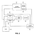
- FIG. 2 is a block diagram showing one embodiment of a lubricant distribution and containment system for use in the gas turbine engine 10.
- the illustrated system includes a scavenge pump 30, a pressure pump 32 and a tank 34.
- a gearbox 36 is powered by operation of the gas turbine engine 10, that is, by the rotation of at least one of the spools 12 and 14. Power is transmitted from the gearbox 36 to the scavenge pump 30 and to the pressure pump 32 by a drive shaft 38.
- An engine controller 40 can generate control signals for controlling operation of the scavenge pump 30 and the pressure pump 32.
- an engine compartment 42 having a sealed opening 44 that enables a movable component, such as a rotatable shaft, to pass through a wall of the compartment 42. Sealing at the opening 44 can be provided by a labyrinth seal, or other suitable sealing structure of a known configuration. It should be noted that the system can include additional components that are not shown in FIG. 2 for simplicity.
- the pressure pump 32 moves a fluid such as oil or other lubricant and/or coolant, to the engine compartment 42 from the tank 34, which acts as a reservoir.
- the scavenge pump 30 moves oil from the engine compartment back to the tank 34.
- the oil can pass through a heat exchanger (not shown) before returning to the tank 34, in order to remove thermal energy from the oil that was absorbed in the compartment 42. In this way, oil moves in a circuit between the compartment 42 and the tank 34, which can remove thermal energy from the compartment 42 where heat-sensitive and friction-sensitive components like bearings are typically located.
- the engine compartment 42 is negatively pressurized, creating a partial vacuum, for instance decreasing pressure in the compartment 42 by up to about a 3.4 kPa differential (0.5 pounds per square inch differential (psid)) at low power engine operation, e.g., idle conditions.
- This negative pressurization of the compartment 42 creates an air curtain at the opening 44, which reduces a risk of oil (e.g., oil droplets) leaking from the compartment 42 through the sealed opening 44.
- the scavenge pump 30 and the pressure pump 32 are each variable positive displacement pumps (e.g., variable displacement ring pumps, vane pumps, etc.), and the drive shaft 38 provides rotational input to both the pumps 30 and 32 when the engine 10 is operating.
- the amount of rotational input provided to the pumps 30 and 32 by the drive shaft 38 can be proportional to operational speed of the spools 12 and 14 of the engine 10 as determined by a gear ratio of the gearbox 36.
- fluid outputs of each of the pumps 30 and 32 can be varied, by adjusting displacement of each pump 30 and 32 according to command signals from the engine controller 40, as explained further below.
- the pressure pump 32 and/or the scavenge pump 30 can be electrically powered pumps.
- the configuration can be generally similar to that shown in FIG. 2 , but the drive shaft 38 and the gearbox 36 can be omitted.
- Electrical power to the pumps 30 and 32 can be supplied by a conventional generator known for use with gas turbine engines.
- the generator can be an existing one present in the engine 10 used for other functions, with the generator having an output capacity selected to accommodate the additional electrical power requirements of the pumps 30 and 32, or can be an additional generator dedicated to providing electrical power to the pumps 30 and 32.
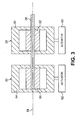
- FIGS. 3 and 4 are cross-sectional views of portions of an embodiment of the lubricant distribution and containment system of the present invention using mechanically-powered variable displacement pumps.
- FIG. 3 is a cross-sectional view of a portion of the system
- FIG. 4 is another cross-sectional view of a portion of the system taken perpendicular to the view shown in FIG. 3 .
- the scavenge pump 30 and the pressure pump 32 are arranged in a stacked configuration on the common drive shaft 38.
- the scavenge pump 30 can be arranged closer to the gearbox 36 (not shown in FIG. 3 ) than the pressure pump 32.
- This stacked arrangement helps conserve space and weight.
- the stacked arrangement also provides an additional safety benefit in that the common drive shaft 38 provides rotational input to both the scavenge pump 30 and the pressure pump 32, therefore a pump seizure or loss of rotational power causes both pumps 30 and 32 to halt, reducing a risk of flooding of the engine compartment 42 and associated risks of auto-ignition.
- the illustrated scavenge pump 30 includes a housing 50 and a rotor 52 positioned within the housing 50.
- the illustrated pressure pump 32 is substantially similar to the scavenge pump 30, and includes a housing 54 and a rotor 56.
- the rotors 52 and 56 are both connected to the drive shaft 38, and can rotate about an axis 58.
- the housings 50 and 54 are connected to actuators 60 and 62 (e.g., solenoid actuators, hydraulic actuators, etc.), respectively, that can independently reposition the housings 50 and 54 relative to the axis 58 about which the rotors 52 and 56 can rotate.
- the actuators 60 and 62 can each be controlled by command signals from the engine controller 40 (not shown in FIG. 3 ).
- FIG. 4 shows the scavenge pump 30.
- the pressure pump 32 is configured similarly to the scavenge pump 30, and so description of internal workings of the scavenge pump 30 applies equally to the pressure pump 32.
- the housing 50 includes an inlet port 64 and an outlet port 66 through which oil can flow.
- the rotor 52 is positioned within an interior chamber of the housing 50, and is powered by rotational input from the drive shaft 38.
- the drive shaft 38 and the rotor 52 rotate about the fixed axis 58.
- a plurality of vanes 68 extend radially outward from the rotor 52 to an interior surface of the housing 50.
- the housing 50 can be repositioned by the actuator 60 relative to the axis 58.
- This means that the housing 50 is positioned eccentrically relative to the rotor 52 and vanes 68 to provide variable displacement of fluid pumped from the inlet port 64 to the outlet port 66.
- the vanes 68 can flex, telescope or otherwise adjust to follow the interior surface of the housing 50 as the rotor 52 rotates, in order to accommodate various positioning of the housing 50.
- the command signals sent by the engine controller 40 to the actuator 60 can be selected according to a fixed schedule determined as a function of throttle level, or can be dynamically adjusted using feedback from an optional sensor 46 ( FIG. 2 ) that detects operational parameters at the compartment 42. It should be noted that the specific number of vanes 68 can vary as desired for particular applications, as can the overall size of the scavenge pump 30.
- the present embodiment allows flow output of the scavenge pump 30 and the pressure pump 32 to be independently dynamically adjusted to maintain desired oil flow and oil containment across a variety of operational conditions.
- the present embodiment allows oil flow to the compartment 42 to be selected according to relatively precise requirements for particular engine operational speeds, thereby increasing efficiency.
- Adjustment of the displacement of the scavenge pump 30 independent from (or decoupled from) the pressure pump 32 according to the present embodiment also allows adjustment of suction provided to the location where the scavenge pump 30 draws fluid, namely the engine compartment 42, in order to better maintain air curtains and to generally enhance oil containment.
- the present invention provides a relatively low-weight pumping system, and, in some embodiments, can utilize a common drive shaft for added safety.
- the actuator 60 for the scavenge pump 30 can be adjusted separately from the actuator 62 for the pressure pump 32.
- the suction provided by the scavenge pump 30 to evacuate the engine compartment 42 can be increased while still delivering an adequate oil flow with the pressure pump 32.
- the flow output of the scavenge pump 30 may always remain greater than that of the pressure pump 32, such as at a 2:1 ratio, in order to avoid flooding in the engine compartment 42 and to reduce a risk of auto-ignition of the oil.
- the present invention allows adjustment of flow outputs of the pressure pump 32 and the scavenge pump 30 to be adjusted at different rates, that is, adjusted independently.
- the flow output ratio between the scavenge pump 30 and the pressure pump 32 can change from 2:1 to 3:1 under certain operating conditions.
- the particular rate of change in flow outputs can be selected as a function of desired fluid delivery and removal rates, desired compartment pressurization, among other factors.
- the particular conditions at which the displacement of the scavenge pump 30 is increased over that of the pressure pump 32 can be selected as desired for particular applications. For instance, at relatively low engine operational speeds it may be desirable to increase displacement of the scavenge pump 30 over that of the pressure pump 32, which can operate at a relatively lower displacement matched to the relatively low oil flow demands associated with such engine operational speeds.
- FIG. 5 is an exploded perspective view of a portion of an embodiment of the lubricant distribution and containment system with a mechanical linkage assembly between the scavenge pump 30 and the pressure pump 32.
- the housings 50 and 54 for the scavenge pump 30 and the pressure pump 32, respectively, are each pivotally supported at a bottom dead center location aligned along a common axis 70.
- the mechanical linkage assembly in the illustrated embodiment includes a pin 72 extending from the housing 50 of the scavenge pump 30 and a corresponding arcuate slot 74 located in the housing 54 of the pressure pump 32.
- the pin 72 In an assembled configuration, the pin 72 is inserted into the slot 74. In this configuration, actuation by the actuator 62 can cause the pin 72 to move within the slot 74 within a selected range of movement. It should be noted that in alternative embodiments, the pin 72 can be located on the housing 54 and the slot 74 on the housing 50.
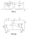
- FIGS. 6A-6C are views of alternative embodiments of actuation and mechanical linkage assemblies for the lubricant distribution and containment system.
- FIG. 6A illustrates a first embodiment where the actuator 60 connected to the housing 50 of the scavenge pump 30 is mounted to an external "ground” location, and the actuator 62 connected to the housing 54 of the pressure pump 32 is mounted to an external "ground” location.
- actuation of the actuator 62 moves both the housings 50 and 54, because the pin 72 will contact a circumferential extent of the slot 74.
- An additional actuation stroke can be achieved for the scavenge pump 30, as desired, through actuation of the actuator 60.
- the actuation stroke of the actuator 62 for the pressure pump 32 is ⁇ L A and the actuation stroke of the actuator 60 for the scavenge pump 30 is ⁇ L A + ⁇ L B .
- the actuator 60 is shown in a fully extended state with ⁇ L B at its maximum and the pin 72 at one end of the slot 74. Actuation of the actuator 60 can reduce ⁇ L B to zero, with the pin 72 moving to the opposite end of the slot 74.
- FIG. 6B illustrates a second embodiment where the actuator 62 connected to the housing 54 of the pressure pump 32 is mounted to an external "ground" location and the actuator 60 for the scavenge pump 30 is supported by a beam (or support bracket) 76 extending from the housing 54 of the pressure pump 32.
- the actuation stroke of the actuator 62 for the pressure pump 32 is ⁇ L A
- the actuation stroke of the actuator 60 for the scavenge pump 30 is ⁇ L A + ⁇ L B .
- the movement of the housing 54 causes movement of the beam 76, which displaces the actuator 60 and in turn the housing 50.
- the actuator 60 is shown in a fully extended state with ⁇ L B at its maximum.
- FIG. 6C illustrates a third embodiment where the actuator 62 connected to the housing 54 of the pressure pump 32 is mounted to an external "ground” location and the actuator 60 is mounted between the housing 54 of the pressure pump 32 and a beam (or support bracket) 78 extending from the housing 50 of the scavenge pump 30.
- the actuators 60 and 62 are arranged to oppose one another.
- the actuation stroke of the actuator 62 for the pressure pump 32 is ⁇ L A
- the actuation stroke of the actuator 60 for the scavenge pump 30 is ⁇ L A + ⁇ L B .
- the actuator 60 is shown in a fully extended state with ⁇ L B at its maximum.
- control of the actuators 60 and 62 can vary as desired for particular applications.
- the particular fluid circulated by the system of the present invention can be any suitable coolant or lubricant.
Landscapes
- Engineering & Computer Science (AREA)
- General Engineering & Computer Science (AREA)
- Mechanical Engineering (AREA)
- Chemical & Material Sciences (AREA)
- Combustion & Propulsion (AREA)
- Lubrication Of Internal Combustion Engines (AREA)
Applications Claiming Priority (1)
| Application Number | Priority Date | Filing Date | Title |
|---|---|---|---|
| US12/001,661 US7931124B2 (en) | 2007-12-12 | 2007-12-12 | On-demand lubrication system and method for improved flow management and containment |
Publications (3)
| Publication Number | Publication Date |
|---|---|
| EP2071140A2 true EP2071140A2 (fr) | 2009-06-17 |
| EP2071140A3 EP2071140A3 (fr) | 2013-06-19 |
| EP2071140B1 EP2071140B1 (fr) | 2018-11-14 |
Family
ID=40451305
Family Applications (1)
| Application Number | Title | Priority Date | Filing Date |
|---|---|---|---|
| EP08253956.0A Ceased EP2071140B1 (fr) | 2007-12-12 | 2008-12-10 | Système de circulation d'huile et procédé de gestion du flux d'huile |
Country Status (2)
| Country | Link |
|---|---|
| US (2) | US7931124B2 (fr) |
| EP (1) | EP2071140B1 (fr) |
Cited By (2)
| Publication number | Priority date | Publication date | Assignee | Title |
|---|---|---|---|---|
| EP2426320A1 (fr) * | 2010-06-15 | 2012-03-07 | Hamilton Sundstrand Corporation | Système d'actionnement de moteur à turbine à gaz commandé par lubrification |
| EP3060779A4 (fr) * | 2013-10-24 | 2017-07-26 | United Technologies Corporation | Systèmes de graissage de turbine à gaz |
Families Citing this family (27)
| Publication number | Priority date | Publication date | Assignee | Title |
|---|---|---|---|---|
| JP4993688B2 (ja) * | 2006-11-15 | 2012-08-08 | オークマ株式会社 | 主軸潤滑装置 |
| US8572974B2 (en) * | 2009-07-31 | 2013-11-05 | Hamilton Sundstrand Corporation | Variable speed and displacement electric fluid delivery system for a gas turbine engine |
| US9051878B2 (en) | 2011-06-22 | 2015-06-09 | Hamilton Sundstrand Corporation | Engine bearing compartment |
| US10247095B2 (en) | 2012-09-28 | 2019-04-02 | United Technologies Corporation | Reduced trim flow gas turbine engine oil system |
| US9777639B2 (en) | 2012-12-23 | 2017-10-03 | United Technologies Corporation | Turbine engine gearbox mount with multiple fuse joints |
| US9500133B2 (en) | 2012-12-23 | 2016-11-22 | United Technologies Corporation | Mount with an axial upstream linkage for connecting a gearbox to a turbine engine case |
| EP2954185B1 (fr) | 2013-02-06 | 2022-05-04 | Raytheon Technologies Corporation | Système de lubrification à circuits multiples pour moteur de turbine |
| EP2954212B1 (fr) | 2013-02-06 | 2020-10-21 | United Technologies Corporation | Système de lubrification à circuits multiples pour un moteur à turbine |
| WO2014152347A2 (fr) * | 2013-03-15 | 2014-09-25 | United Technologies Corporation | Circulation d'un lubrifiant à travers un composant de moteur de turbine comportant des pompes parallèles |
| WO2015021007A1 (fr) * | 2013-08-05 | 2015-02-12 | Charles Tuckey | Ensemble pompe à palettes |
| WO2015047577A1 (fr) * | 2013-09-26 | 2015-04-02 | United Technologies Corporation | Moteur à turbine à gaz avec système de lubrification fractionné |
| US9784150B2 (en) * | 2013-10-28 | 2017-10-10 | Cummins Ip, Inc. | Lubricant level control for lubricated systems |
| US9683652B2 (en) * | 2015-04-22 | 2017-06-20 | Bell Helicopter Textron Inc. | Method for the delivery of lubricant to a rotorcraft gearbox |
| US10260420B2 (en) | 2015-05-19 | 2019-04-16 | Rolls-Royce Corporation | Lubrication system for a reconfigurable gas turbine engine |
| US9909453B2 (en) | 2015-05-19 | 2018-03-06 | General Electric Company | Lubrication system for a turbine engine |
| US9759094B2 (en) * | 2015-06-24 | 2017-09-12 | General Electric Company | Pump for a turbine engine |
| US10415429B2 (en) | 2015-09-25 | 2019-09-17 | General Electric Company | Planet gearbox with cylindrical roller bearing with high density roller packing |
| US10234018B2 (en) | 2015-10-19 | 2019-03-19 | General Electric Company | Planet gearbox with cylindrical roller bearing with under race lube scheme |
| ITUB20156062A1 (it) | 2015-12-01 | 2017-06-01 | Gen Electric | Alloggiamento per l'uso in un motore a turboventilatore e procedimento di lavaggio di fluido da esso. |
| US10060290B2 (en) | 2015-12-30 | 2018-08-28 | General Electric Company | Method and system for centrifugal pump |
| US10619567B2 (en) | 2016-04-29 | 2020-04-14 | Rolls-Royce Corporation | Reconfigurable lubrication system for multiple powertrain orientations |
| PL421044A1 (pl) | 2017-03-30 | 2018-10-08 | General Electric Company | Układ oraz sposób dla pompy strumieniowej silnika zasilanej przez zamienny układ regulacji przepływu powietrza |
| US11230947B2 (en) | 2019-06-20 | 2022-01-25 | Pratt & Whitney Canada Corp. | Gas turbine engine having oil level measurement system |
| FR3112365B1 (fr) * | 2020-07-09 | 2022-07-29 | Safran Helicopter Engines | Procede de demarrage d’un moteur d’aeronef |
| FR3117093B1 (fr) * | 2020-12-03 | 2024-03-22 | Airbus Sas | Système de propulsion électrique d’un aéronef. |
| US12421898B2 (en) | 2022-06-22 | 2025-09-23 | General Electric Company | Gearbox assembly with lubricant extraction volume ratio |
| US12257124B1 (en) | 2024-05-01 | 2025-03-25 | Amrish Patel | Dental robot |
Citations (1)
| Publication number | Priority date | Publication date | Assignee | Title |
|---|---|---|---|---|
| US7174876B2 (en) | 2004-06-22 | 2007-02-13 | Toyota Jidosha Kabushiki Kaisha | Control apparatus for dry sump type internal combustion engine |
Family Cites Families (33)
| Publication number | Priority date | Publication date | Assignee | Title |
|---|---|---|---|---|
| US2511150A (en) | 1944-04-03 | 1950-06-13 | Edwards Miles Lowell | Scavenge pump |
| US2642155A (en) * | 1948-05-14 | 1953-06-16 | Westinghouse Electric Corp | Lubrication apparatus |
| US2672010A (en) | 1951-07-14 | 1954-03-16 | United Aircraft Corp | Pressurized lubrication system for gas turbines |
| US2672278A (en) | 1951-07-14 | 1954-03-16 | United Aircraft Corp | Lubrication system for gas turbine power plants |
| US2680433A (en) * | 1952-07-18 | 1954-06-08 | Us Air Force | Simplified lubricating system for jet engines |
| US2996146A (en) * | 1958-10-13 | 1961-08-15 | Gen Motors Corp | Lubrication system |
| US3067693A (en) | 1958-12-24 | 1962-12-11 | United Aircraft Corp | Control means for variable delivery pump |
| US3027971A (en) * | 1960-04-13 | 1962-04-03 | Jr Albert E Ketler | Engine lubrication system |
| GB1170328A (en) * | 1967-10-25 | 1969-11-12 | Hawker Siddeley Aviation Ltd | Improvements in or relating to Aircraft Gas Turbine Jet Engine Air Intakes |
| US3527054A (en) | 1969-01-23 | 1970-09-08 | Gen Electric | Pressurization of lubrication sumps in gas turbine engines |
| US3722624A (en) * | 1971-06-07 | 1973-03-27 | Gen Electric | Bearing seal and oil tank ventilation system |
| GB1429677A (en) * | 1973-03-20 | 1976-03-24 | Rolls Royce | Gas turbine engine combustion equipment |
| GB1592571A (en) * | 1977-05-18 | 1981-07-08 | Nat Res Dev | Cathode ray tubes |
| US4205525A (en) | 1978-03-17 | 1980-06-03 | Teledyne Industries, Inc. | Turbine engine lubrication system |
| US5214984A (en) | 1990-12-06 | 1993-06-01 | Jatco Corporation | Pressure control system for automotive automatic power transmission with feature of fluid pressure dependent actuator control |
| US5152141A (en) | 1991-04-08 | 1992-10-06 | Avco Corporation | Management of electrically driven engine accessories |
| KR100275161B1 (ko) | 1992-07-09 | 2000-12-15 | 허버트 지. 버카드 | 전기 장치 |
| GB9220991D0 (en) | 1992-10-06 | 1992-11-18 | Dowty Defence | Lubrication system |
| US6564556B2 (en) * | 1992-10-27 | 2003-05-20 | J. Lyell Ginter | High efficiency low pollution hybrid brayton cycle combustor |
| EP1067282A2 (fr) | 1993-03-03 | 2001-01-10 | KETEMA AEROSPACE & ELECTRONICS DIVISION | Système de commande integré pour une turbine à gaz |
| JPH06307325A (ja) | 1993-04-27 | 1994-11-01 | Fuji Electric Co Ltd | 直接加圧式圧油装置 |
| FR2705733B1 (fr) * | 1993-05-25 | 1995-06-30 | Snecma | Dispositif de dépressurisation des chambres de lubrification entourant les paliers d'une turbomachine. |
| US5411116A (en) | 1994-06-22 | 1995-05-02 | United Technologies Corporation | Self-scavenging, hybrid lubrication subsystem |
| US5513732A (en) | 1994-08-05 | 1996-05-07 | Ford Motor Company | Regulation of hydraulic pressure in a system having multiple pressure sources |
| US6094907A (en) * | 1996-06-05 | 2000-08-01 | The Boeing Company | Jet engine and method for reducing jet engine noise by reducing nacelle boundary layer thickness |
| NL1013446C2 (nl) * | 1999-11-01 | 2001-05-02 | Skf Eng & Res Centre Bv | Inrichting in een smeermiddelpomp. |
| EP1130221A1 (fr) | 2000-02-14 | 2001-09-05 | Techspace Aero S.A. | Procédé et dispositif de lubrification pour moteur aeronautique |
| US7674095B2 (en) * | 2000-12-12 | 2010-03-09 | Borgwarner Inc. | Variable displacement vane pump with variable target regulator |
| US6470666B1 (en) | 2001-04-30 | 2002-10-29 | General Electric Company | Methods and systems for preventing gas turbine engine lube oil leakage |
| US6877950B2 (en) * | 2001-11-29 | 2005-04-12 | Pratt & Whitney Canada Corp. | Method and device for minimizing oil consumption in a gas turbine engine |
| GB0218849D0 (en) | 2002-08-14 | 2002-09-25 | Rolls Royce Plc | Lubrication system for gas turbine engine |
| US7426834B2 (en) | 2004-02-03 | 2008-09-23 | General Electric Company | “Get home” oil supply and scavenge system |
| US7571597B2 (en) | 2006-01-25 | 2009-08-11 | Honeywell International Inc. | Airframe mounted motor driven lubrication pump control system and method |
-
2007
- 2007-12-12 US US12/001,661 patent/US7931124B2/en active Active
-
2008
- 2008-12-10 EP EP08253956.0A patent/EP2071140B1/fr not_active Ceased
-
2011
- 2011-02-22 US US13/032,157 patent/US8256576B2/en not_active Expired - Fee Related
Patent Citations (1)
| Publication number | Priority date | Publication date | Assignee | Title |
|---|---|---|---|---|
| US7174876B2 (en) | 2004-06-22 | 2007-02-13 | Toyota Jidosha Kabushiki Kaisha | Control apparatus for dry sump type internal combustion engine |
Cited By (4)
| Publication number | Priority date | Publication date | Assignee | Title |
|---|---|---|---|---|
| EP2426320A1 (fr) * | 2010-06-15 | 2012-03-07 | Hamilton Sundstrand Corporation | Système d'actionnement de moteur à turbine à gaz commandé par lubrification |
| US9151180B2 (en) | 2010-06-15 | 2015-10-06 | Hamilton Sundstrand Corporation | Lubrication driven gas turbine engine actuation system |
| EP3060779A4 (fr) * | 2013-10-24 | 2017-07-26 | United Technologies Corporation | Systèmes de graissage de turbine à gaz |
| US10082077B2 (en) | 2013-10-24 | 2018-09-25 | United Technologies Corporation | Gas turbine lubrication systems |
Also Published As
| Publication number | Publication date |
|---|---|
| EP2071140A3 (fr) | 2013-06-19 |
| US20090152051A1 (en) | 2009-06-18 |
| US7931124B2 (en) | 2011-04-26 |
| EP2071140B1 (fr) | 2018-11-14 |
| US8256576B2 (en) | 2012-09-04 |
| US20110155508A1 (en) | 2011-06-30 |
Similar Documents
| Publication | Publication Date | Title |
|---|---|---|
| US7931124B2 (en) | On-demand lubrication system and method for improved flow management and containment | |
| US8572974B2 (en) | Variable speed and displacement electric fluid delivery system for a gas turbine engine | |
| US8196385B2 (en) | Turbomachine control system | |
| EP2224120B1 (fr) | Pompe de lubrification auxiliaire pour train de transmission à engrenages de turboréacteur | |
| US5918573A (en) | Energy efficient fluid pump | |
| EP3382163B1 (fr) | Système de lubrification de moteur à turbine à gaz, moteur à turbine à gaz comportant un système de pompe de suralimentation et procédé correspondant | |
| JP2007518615A (ja) | プロペラエンジン装置用の加圧オイル供給 | |
| EP0298011A1 (fr) | Système de lubrification et de refroidissement monté dans un capot de nez de rotor | |
| EP3208195B1 (fr) | Système de ventilateur de cabine | |
| US20180050812A1 (en) | Aircraft fuel pump systems | |
| AU2009312746A1 (en) | Wind turbine lubrication system | |
| EP0712466B1 (fr) | Pompe centrifuge de carburant avec etage de demarrage | |
| EP2584175A2 (fr) | Fonctionnement d'une turbine à gaz | |
| US20190186418A1 (en) | Multi-Hybrid Aircraft Engine | |
| US12577891B2 (en) | Auxiliary oil supply device for an aircraft turbine engine | |
| CN110234857B (zh) | 用于向涡轮机供应燃料的系统 | |
| US20240401530A1 (en) | Turbine engine comprising an oil supply system | |
| US20250361821A1 (en) | Integrated in-line emergency lube pump assembly for planetary gearbox configurations | |
| EP0657651A1 (fr) | Pompe | |
| EP1111273A2 (fr) | Système de régulation de la pression hydraulique pour des conditions de vol en "g" négatif | |
| US20250035013A1 (en) | Method of operating a lubrication system for a turbine engine | |
| US12428977B2 (en) | Auxiliary oil tank for an aircraft turbine engine | |
| US12281581B1 (en) | Module for an aircraft turbine engine | |
| US12110826B2 (en) | Assembly for aircraft turbine engine comprising an improved system for lubricating a fan drive reduction gear | |
| EP2604791A2 (fr) | Moteur à propulsion |
Legal Events
| Date | Code | Title | Description |
|---|---|---|---|
| PUAI | Public reference made under article 153(3) epc to a published international application that has entered the european phase |
Free format text: ORIGINAL CODE: 0009012 |
|
| AK | Designated contracting states |
Kind code of ref document: A2 Designated state(s): AT BE BG CH CY CZ DE DK EE ES FI FR GB GR HR HU IE IS IT LI LT LU LV MC MT NL NO PL PT RO SE SI SK TR |
|
| AX | Request for extension of the european patent |
Extension state: AL BA MK RS |
|
| RIC1 | Information provided on ipc code assigned before grant |
Ipc: F02C 7/06 20060101ALI20130128BHEP Ipc: F01M 1/02 20060101ALI20130128BHEP Ipc: F16N 7/38 20060101ALI20130128BHEP Ipc: F01D 25/20 20060101AFI20130128BHEP |
|
| PUAL | Search report despatched |
Free format text: ORIGINAL CODE: 0009013 |
|
| AK | Designated contracting states |
Kind code of ref document: A3 Designated state(s): AT BE BG CH CY CZ DE DK EE ES FI FR GB GR HR HU IE IS IT LI LT LU LV MC MT NL NO PL PT RO SE SI SK TR |
|
| AX | Request for extension of the european patent |
Extension state: AL BA MK RS |
|
| RIC1 | Information provided on ipc code assigned before grant |
Ipc: F16N 7/38 20060101ALI20130513BHEP Ipc: F01D 25/20 20060101AFI20130513BHEP Ipc: F02C 7/06 20060101ALI20130513BHEP Ipc: F01M 1/02 20060101ALI20130513BHEP |
|
| 17P | Request for examination filed |
Effective date: 20131219 |
|
| RBV | Designated contracting states (corrected) |
Designated state(s): AT BE BG CH CY CZ DE DK EE ES FI FR GB GR HR HU IE IS IT LI LT LU LV MC MT NL NO PL PT RO SE SI SK TR |
|
| AKX | Designation fees paid |
Designated state(s): DE GB |
|
| RAP1 | Party data changed (applicant data changed or rights of an application transferred) |
Owner name: UNITED TECHNOLOGIES CORPORATION |
|
| GRAP | Despatch of communication of intention to grant a patent |
Free format text: ORIGINAL CODE: EPIDOSNIGR1 |
|
| STAA | Information on the status of an ep patent application or granted ep patent |
Free format text: STATUS: GRANT OF PATENT IS INTENDED |
|
| INTG | Intention to grant announced |
Effective date: 20180531 |
|
| GRAS | Grant fee paid |
Free format text: ORIGINAL CODE: EPIDOSNIGR3 |
|
| GRAA | (expected) grant |
Free format text: ORIGINAL CODE: 0009210 |
|
| STAA | Information on the status of an ep patent application or granted ep patent |
Free format text: STATUS: THE PATENT HAS BEEN GRANTED |
|
| AK | Designated contracting states |
Kind code of ref document: B1 Designated state(s): DE GB |
|
| REG | Reference to a national code |
Ref country code: GB Ref legal event code: FG4D |
|
| REG | Reference to a national code |
Ref country code: DE Ref legal event code: R096 Ref document number: 602008057883 Country of ref document: DE |
|
| REG | Reference to a national code |
Ref country code: DE Ref legal event code: R097 Ref document number: 602008057883 Country of ref document: DE |
|
| PLBE | No opposition filed within time limit |
Free format text: ORIGINAL CODE: 0009261 |
|
| STAA | Information on the status of an ep patent application or granted ep patent |
Free format text: STATUS: NO OPPOSITION FILED WITHIN TIME LIMIT |
|
| 26N | No opposition filed |
Effective date: 20190815 |
|
| PGFP | Annual fee paid to national office [announced via postgrant information from national office to epo] |
Ref country code: GB Payment date: 20211118 Year of fee payment: 14 |
|
| REG | Reference to a national code |
Ref country code: DE Ref legal event code: R081 Ref document number: 602008057883 Country of ref document: DE Owner name: RAYTHEON TECHNOLOGIES CORPORATION (N.D.GES.D.S, US Free format text: FORMER OWNER: UNITED TECHNOLOGIES CORP., FARMINGTON, CONN., US |
|
| PGFP | Annual fee paid to national office [announced via postgrant information from national office to epo] |
Ref country code: DE Payment date: 20220616 Year of fee payment: 15 |
|
| GBPC | Gb: european patent ceased through non-payment of renewal fee |
Effective date: 20221210 |
|
| PG25 | Lapsed in a contracting state [announced via postgrant information from national office to epo] |
Ref country code: GB Free format text: LAPSE BECAUSE OF NON-PAYMENT OF DUE FEES Effective date: 20221210 |
|
| REG | Reference to a national code |
Ref country code: DE Ref legal event code: R119 Ref document number: 602008057883 Country of ref document: DE |
|
| PG25 | Lapsed in a contracting state [announced via postgrant information from national office to epo] |
Ref country code: DE Free format text: LAPSE BECAUSE OF NON-PAYMENT OF DUE FEES Effective date: 20240702 |
|
| PG25 | Lapsed in a contracting state [announced via postgrant information from national office to epo] |
Ref country code: DE Free format text: LAPSE BECAUSE OF NON-PAYMENT OF DUE FEES Effective date: 20240702 |