EP2071174B1 - Strahldüse zur Dämpfung mittels Bohrung - Google Patents
Strahldüse zur Dämpfung mittels Bohrung Download PDFInfo
- Publication number
- EP2071174B1 EP2071174B1 EP07122785A EP07122785A EP2071174B1 EP 2071174 B1 EP2071174 B1 EP 2071174B1 EP 07122785 A EP07122785 A EP 07122785A EP 07122785 A EP07122785 A EP 07122785A EP 2071174 B1 EP2071174 B1 EP 2071174B1
- Authority
- EP
- European Patent Office
- Prior art keywords
- jet
- fuel
- cylindrical body
- orifice
- flat region
- Prior art date
- Legal status (The legal status is an assumption and is not a legal conclusion. Google has not performed a legal analysis and makes no representation as to the accuracy of the status listed.)
- Active
Links
- 238000013016 damping Methods 0.000 title claims abstract description 12
- 239000000446 fuel Substances 0.000 claims abstract description 74
- 238000002485 combustion reaction Methods 0.000 claims abstract description 24
- 238000000034 method Methods 0.000 claims abstract description 12
- 238000004519 manufacturing process Methods 0.000 claims description 5
- 239000002184 metal Substances 0.000 description 7
- 230000000694 effects Effects 0.000 description 3
- 239000004215 Carbon black (E152) Substances 0.000 description 1
- 230000006835 compression Effects 0.000 description 1
- 238000007906 compression Methods 0.000 description 1
- 238000005553 drilling Methods 0.000 description 1
- 239000012530 fluid Substances 0.000 description 1
- 238000009499 grossing Methods 0.000 description 1
- 238000010438 heat treatment Methods 0.000 description 1
- 229930195733 hydrocarbon Natural products 0.000 description 1
- 150000002430 hydrocarbons Chemical class 0.000 description 1
- 238000002347 injection Methods 0.000 description 1
- 239000007924 injection Substances 0.000 description 1
- 238000003754 machining Methods 0.000 description 1
- 230000001902 propagating effect Effects 0.000 description 1
- 238000011144 upstream manufacturing Methods 0.000 description 1
Images


Classifications
-
- F—MECHANICAL ENGINEERING; LIGHTING; HEATING; WEAPONS; BLASTING
- F02—COMBUSTION ENGINES; HOT-GAS OR COMBUSTION-PRODUCT ENGINE PLANTS
- F02M—SUPPLYING COMBUSTION ENGINES IN GENERAL WITH COMBUSTIBLE MIXTURES OR CONSTITUENTS THEREOF
- F02M55/00—Fuel-injection apparatus characterised by their fuel conduits or their venting means; Arrangements of conduits between fuel tank and pump F02M37/00
- F02M55/02—Conduits between injection pumps and injectors, e.g. conduits between pump and common-rail or conduits between common-rail and injectors
- F02M55/025—Common rails
-
- F—MECHANICAL ENGINEERING; LIGHTING; HEATING; WEAPONS; BLASTING
- F02—COMBUSTION ENGINES; HOT-GAS OR COMBUSTION-PRODUCT ENGINE PLANTS
- F02M—SUPPLYING COMBUSTION ENGINES IN GENERAL WITH COMBUSTIBLE MIXTURES OR CONSTITUENTS THEREOF
- F02M55/00—Fuel-injection apparatus characterised by their fuel conduits or their venting means; Arrangements of conduits between fuel tank and pump F02M37/00
- F02M55/04—Means for damping vibrations or pressure fluctuations in injection pump inlets or outlets
-
- F—MECHANICAL ENGINEERING; LIGHTING; HEATING; WEAPONS; BLASTING
- F02—COMBUSTION ENGINES; HOT-GAS OR COMBUSTION-PRODUCT ENGINE PLANTS
- F02M—SUPPLYING COMBUSTION ENGINES IN GENERAL WITH COMBUSTIBLE MIXTURES OR CONSTITUENTS THEREOF
- F02M2200/00—Details of fuel-injection apparatus, not otherwise provided for
- F02M2200/28—Details of throttles in fuel-injection apparatus
-
- F—MECHANICAL ENGINEERING; LIGHTING; HEATING; WEAPONS; BLASTING
- F02—COMBUSTION ENGINES; HOT-GAS OR COMBUSTION-PRODUCT ENGINE PLANTS
- F02M—SUPPLYING COMBUSTION ENGINES IN GENERAL WITH COMBUSTIBLE MIXTURES OR CONSTITUENTS THEREOF
- F02M2200/00—Details of fuel-injection apparatus, not otherwise provided for
- F02M2200/31—Fuel-injection apparatus having hydraulic pressure fluctuations damping elements
- F02M2200/315—Fuel-injection apparatus having hydraulic pressure fluctuations damping elements for damping fuel pressure fluctuations
Definitions
- the present invention relates to a jet for providing orifice damping in the fuel delivery system of a compression-ignition combustion engine, a fuel delivery system for a compression-ignition combustion engine comprising such a jet, and to a method of manufacturing a jet for providing orifice damping in the fuel delivery system of a compression-ignition combustion engine.
- combustion takes place in one or more combustion chambers or cylinders. Air is compressed in the cylinder by a piston and fuel is injected into the compressed air. The heat of the compressed air spontaneously ignites the fuel in the cylinder.
- Fuel is injected into the cylinders at high pressure, which is typically achieved using a high pressure pump to pressurise fuel in a rail cavity which, in turn, is connected to a plurality of injectors, each of which is associated with one cylinder of the engine.
- Each injector typically comprises a nozzle through which fuel is injected into the corresponding cylinder.
- the flow of fuel through the injector nozzle is controlled by a valve needle which is movable along a primary axis of the injector body and may be lifted from a valve seat adjacent to the nozzle in order to allow fuel to flow through the nozzle and be injected into the cylinder.
- a pressure wave may result in unexpectedly high pressure at the nozzle, causing an increased amount of fuel to be injected into the cylinder when the valve is opened. This could lead to increased hydrocarbon emissions due to incomplete combustion of the fuel in the cylinder.
- a pressure wave may result in unexpectedly low pressure at the nozzle, causing less fuel than expected to be injected into the cylinder when the valve is opened. This may result in reduced engine power output.
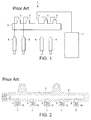
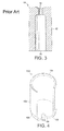
- a known technique for reducing the effect of pressure waves in the fuel delivery system is the inclusion of a jet, in the pipe 5 between the injector 6 and the rail cavity 8, in order to provide orifice damping.
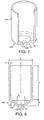
- Figure 3 shows a conventional jet which is used to provide orifice damping in the fuel supplied by a rail to an injector in a diesel engine or gas engine.
- the known jet 10 is formed by machining a metal blank 12 having a substantially cylindrical form.
- An aperture or orifice 14 is formed in one end of the blank 12 such that the flow of fuel into the jet is restricted.
- An axial bore 16 is formed in the opposite end of the blank to create a conduit through which fuel flows from the rail 2 under pressure after it has passed through the orifice 14.
- the reduction in the flow area of the fuel through the orifice 14 before it reaches the injector 6 has the effect of smoothing out any pressure waves which are propagating along the pipe 5 between the injector 6 and the rail 2. Accordingly, fluctuations in the amount of fuel injected when the injector valve is opened are reduced.
- the conventional jet 10 is formed by drilling a blank 12. Additional processing of the blank 12, such as grinding and heat treatment, may also be required. Each of these processing steps incurs a cost which contributes to the total cost of the finished jet.
- DE 10 2005 026 993 describes a fuel injection device for an internal combustion engine, having a high pressure accumulator space comprising a plurality of connecting bores.
- the device comprises at least one restrictor element configured as a pre-shaped component with elastic properties held in a connecting bore.
- a jet for providing orifice damping in the fuel delivery system of a compression-ignition combustion engine wherein the jet is formed by means of a deep draw process and comprises; a hollow cylindrical body having first and second ends, the first end being open to enable unrestricted flow of fuel therethrough, in use, the second end comprising an orifice therein having a smaller cross-sectional area than the opening in the first end, to restrict the flow of fuel therethrough and dampen pressure waves in the fuel, in use, the second end comprising a flat region extending inwardly from and substantially perpendicularly to the wall of the cylindrical body so as to provide resistance to pressure changes occurring in the fuel delivery system, in use.
- the present invention provides a jet which is simple and more economical to manufacture, yet is able to resist the changes of pressure which occur within the fuel delivery system of a compression-ignition combustion engine.
- said flat region comprises a concentric rib or a cruciform rib.
- the jet may advantageously comprise a pair of orifices in the flat region, said pair of orifices being disposed at spaced apart locations equidistant from, and on opposite sides of the primary axis of the cylindrical body.
- the second end comprises a part-spherical region which projects from the flat region and terminates in a second flat region, said orifice being formed in the second flat region.
- the part-spherical region projects outward from the cylindrical body.
- the part-spherical region may project into the cylindrical body.
- a fuel delivery system for a compression-ignition combustion engine comprising a jet as described above; a high pressure pump for pressurising fuel in the delivery system; and a rail cavity for receiving pressurised fuel from the high pressure pump via an inlet pipe, the rail cavity having at least one outlet pipe for conveying fuel to at least one respective fuel injector.
- said jet is disposed in said outlet pipe or said inlet pipe.
- said jet may be disposed between said pump and said rail cavity.
- said jet may be formed integrally with any one of said high pressure pump, said rail cavity, said inlet pipe or said outlet pipe.
- a method of manufacturing a jet for providing orifice damping in the fuel delivery system of a compression-ignition combustion engine comprising; forming hollow a cylindrical body by means of a deep draw process, the cylindrical body comprising first and second ends, the first end being open to enable unrestricted flow of fuel therethrough, in use, the second end comprising an orifice therein having a smaller cross-sectional area than the opening in the first end, to restrict the flow of fuel therethrough and dampen pressure waves in the fuel, in use, the second end comprising a flat region extending inwardly from and substantially perpendicularly to the wall of the cylindrical body so as to provide resistance to pressure changes occurring in the fuel delivery system, in use.
- a deep draw metal forming process is generally performed by stretching sheet metal stock around a punch.
- the sheet metal is clamped around its edges and is pressed into a die cavity by the punch in order to create a product having the desired shape.
- different shapes of product can be produced by varying the respective geometries of the die cavity and the punch.
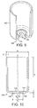
- a first example of a deep drawn jet 100 useful for understanding the present invention comprises a generally cylindrical body 102.
- the cylindrical body 102 has an open end 104 at one end and is formed with a pressure resistant structure 106 at the opposite end.
- the pressure resistant structure 106 comprises a part-spherical portion 108 and a flat portion 109.
- the part-spherical portion 108 extends from the cylindrical body 102 with a constant radius, having its centre at a point on the primary axis (A-A) of the cylindrical body 102.
- the part-spherical portion 108 terminates at the flat portion 109.
- An orifice 110 is formed in the flat portion 109, the orifice 110 being co-axial with the primary axis of the cylindrical body 102.
- the cylindrical body 102 has a wall thickness, s, which is equivalent to the thickness of the metal sheet stock from which the jet 100 is formed.
- the orifice 110 has a diameter d 1
- the flat portion 109 has a diameter d 2
- the part-spherical portion 108 has radius R.
- the jet 100 as shown in Figure 4 is oriented with the open end 104 uppermost. In general, this is the orientation in which the jet 100 is formed by the deep draw process. More specifically, a suitably shaped metal blank is clamped around its edge and a punch presses the blank down into a suitably shaped die cavity. Accordingly, the open end 104 of the resulting jet 100 corresponds to the clamped part of the original metal blank, and the part-spherical portion 108 and flat portion 109 are formed between the punch and the bottom of the die cavity.
- the deep drawn jet 100 when installed in a fuel delivery system in place of the conventional jet 10 shown in Figure 2 , the deep drawn jet 100 will be oriented in the pipe 5 such that the open end 104 is proximal to the injector and the part-spherical portion 108 is proximal to the rail cavity 8. Accordingly, in use, fuel will be pumped from the rail cavity 8, along the pipe 5 through the orifice 110 along the cylindrical body 102 of the jet 100 and out through the open end 104 to the injector 6.
- a finite element analysis (FEA) of the deep drawn jet of Figure 4 determined that it could withstand a pressure difference in excess of 1500 bar in the inlet direction of the jet, i.e. where there is a higher pressure on the rail side of the jet, and similarly a pressure difference in excess of 1500 bar in the outlet direction, i.e. where there is a higher pressure on the injector side of the jet.
- FEA finite element analysis
- a second example of a jet useful for understanding the present invention is similar to that of Figures 4 and 5 , with the exception that there is no flat portion 109 and instead of a single, co-axial orifice 110, there are a pair of orifices 110a, 110b.
- the pair of orifices 110a, 110b are formed in the part-spherical portion 108 at spaced apart locations, equidistant from, and on opposite sides of the primary axis of the cylindrical body 102.
- the distance between the orifices 110a, 110b is labelled d 3 in Figure 6 .
- a finite element analysis (FEA) of the deep drawn jet of Figure 6 determined that it could withstand a pressure difference in excess of 1500 bar in the inlet direction of the jet and similarly a pressure difference in excess of 1500 bar in the outlet direction.
- a first embodiment of a jet according to the invention includes a pressure resistant structure 106 which has a bell-shape, comprising a first flat portion 130, a curved portion 132, and a second flat portion 134.
- the first flat portion 130 extends inwardly and radially from the edge of the cylindrical body 102.
- the curved portion 132 projects from the first flat portion 130 and terminates at the second flat portion 134.
- the curved portion 132 may have a radiussed or part-spheroidal form.
- An orifice 110 is formed in the second flat portion 134, the orifice 110 being co-axial with the primary axis of the cylindrical body 102.
- the height of the cylindrical body 102 is H and the height of the pressure resistant structure 106, i.e. the combined height of the first and second flat portions 130, 134 and the curved portion 132, is h.
- the wall thickness of the cylindrical body 102 is s.
- the diameter of the orifice 110 is d 1 and the diameter of the second flat portion 134 is d 2 .
- H 1 to 1.5D
- d 2 1 to 1.5d 1
- h 2 to 2.5s.
- a finite element analysis (FEA) of the deep drawn jet of Figure 7 determined that it could withstand a pressure difference of around 1200 bar in the inlet direction of the jet and a pressure difference of around 1100 bar in the outlet direction.
- the bell-shaped portion may be inverted such that the curved portion 132 projects into the cylindrical body 102 of the jet 100.
- the second embodiment of a jet according to the invention includes a pressure resistant structure 106 which comprises a concentric rib 140.
- the concentric rib 140 is co-axial with the primary axis of the cylindrical body 102, and is formed in a flat region 142 which extends inwardly and radially from the edge of the cylindrical body 102.
- the orifice 110 is disposed at the centre of the flat region 142 and is formed co-axially with the primary axis of the cylindrical body 102.
- the concentric rib 140 projects from the flat region 142 on the outer surface of the jet 100, and on the opposite side of the flat region 142 there is a correspondingly shaped trough 144.
- the height of the cylindrical body 102 is H and the height of the pressure resistant structure 106, i.e. the height that the concentric rib 140 projects from the surface of the flat region 142, is h.
- the wall thickness of the cylindrical body 102 is s.
- the diameter of the orifice 110 is d 1 and the inner diameter of the concentric rib 140 is d 2 .
- H 1 to 1.5D
- d 2 1 to 1.5d 1
- h 0.5 to 0.75s.
- a finite element analysis (FEA) of the deep drawn jet of Figure 9 determined that it could withstand a pressure difference of around 800 bar in the inlet direction of the jet and a pressure difference of around 700 bar in the outlet direction.
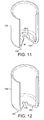
- the third example of a jet useful for understanding the invention includes a pressure resistant structure 106 which comprises an inverted spherical shape 150.
- the third example is similar to the first example, with the exception that the spherical portion 150 projects into the cylindrical body 102 of the jet 100.
- the radius of curvature of the inverted spherical shape 150 is labelled r.
- a finite element analysis (FEA) of the deep drawn jet of Figure 11 determined that it could withstand a pressure difference of around 750 bar in the inlet direction of the jet and a pressure difference of around 850 bar in the outlet direction.
- the third embodiment of a jet according to the invention includes a pressure resistant structure 106 which comprises a flat region 160.
- the flat region 160 extends inwardly and radially from the edge of the cylindrical body 102.
- the orifice 110 is disposed at the centre of the flat region 160 and is formed co-axially with the primary axis of the cylindrical body 102.
- a finite element analysis (FEA) of the deep drawn jet of Figure 12 determined that it could withstand a pressure difference of around 650 bar in the inlet direction of the jet and a pressure difference of around 550 bar in the outlet direction.
- the fourth embodiment of a jet according to the invention is similar to the above-described third embodiment with the exception that there are two orifices 110a, 110b in the flat region 160 rather than a single, centrally located orifice.
- the pair of orifices 110a, 110b are formed in the flat region 160 at spaced apart locations, equidistant from, and on opposite sides of the primary axis of the cylindrical body 102.
- the distance between the orifices 110a, 110b is labelled d 3 in Figure 13 .
- a finite element analysis (FEA) of the deep drawn jet of Figure 13 determined that it could withstand a pressure difference of around 600 bar in the inlet direction of the jet and a pressure difference of around 550 bar in the outlet direction.
- the fifth embodiment of a jet according to the invention includes a pressure resistant structure 106 which comprises a cross-shaped rib 180.
- the cross-shaped rib 180 is centred on the primary axis of the cylindrical body 102, and is formed in a flat region 182 which extends inwardly and radially from the edge of the cylindrical body 102.
- a pair of orifices 110a, 110b are formed in the flat region 182 at spaced apart locations, equidistant from, and on opposite sides of the primary axis of the cylindrical body 102.
- the cross-shaped rib 180 projects from the flat region 182 on the outer surface of the jet 100, and on the opposite side of the flat region 182 there is a correspondingly shaped trough 184.
- the depth of the trough 184 is labelled h, and is equivalent to the distance which the rib 180 projects from the surface of the flat region 182.
- Each arm of the rib 180 has a length L 1 and a width L 2 .
- a finite element analysis (FEA) of the deep drawn jet of Figure 14 determined that it could withstand a pressure difference of around 550 bar in the inlet direction of the jet and a pressure difference of around 550 bar in the outlet direction.
- jets according to the present invention have been described as for use between the rail cavity and the fuel injector of the fuel delivery system of a compression ignition combustion engine, it will be appreciated by those skilled in the art that such jets may advantageously be disposed at other locations within the fuel delivery system.
- a jet may be disposed at the outlet of a high pressure pump used to pressurise fuel in the delivery system, at the inlet or outlets of the common rail volume, or at any other location where it is necessary to reduce the effects of pressure waves within the fuel flow.
Landscapes
- Engineering & Computer Science (AREA)
- Chemical & Material Sciences (AREA)
- Combustion & Propulsion (AREA)
- Mechanical Engineering (AREA)
- General Engineering & Computer Science (AREA)
- Fuel-Injection Apparatus (AREA)
- Perforating, Stamping-Out Or Severing By Means Other Than Cutting (AREA)
- Nozzles (AREA)
Claims (13)
- Strahldüse zur Dämpfung mittels Loch im Kraftstofffördersystem einer Verbrennungskraftmaschine mit Selbstzündung, wobei die Strahldüse (100) durch ein Tiefziehverfahren hergestellt ist und Folgendes umfasst:einen hohlen zylindrischen Körper (102) mit einem ersten und einem zweiten Ende (104, 106),wobei das erste Ende (104) offen ist, um im Gebrauch den ungedrosselten Durchfluss von Kraftstoff durch es hindurch zu ermöglichen,wobei das zweite Ende (106) ein Loch (110) in ihm aufweist, das eine kleinere Querschnittfläche als die Öffnung im ersten Ende (104) hat, um im Gebrauch den Kraftstoffdurchfluss durch es hindurch zu drosseln und Druckwellen im Kraftstoff zu dämpfen, um im Gebrauch Widerstand gegen in dem Kraftstofffördersystem entstehende Druckänderungen zu bieten, dadurch gekennzeichnet, dass das zweite Ende (106) eine flache Region (130; 142; 160; 182) aufweist, die von und im Wesentlichen lotrecht zu der Wand des zylindrischen Körpers (102) einwärts verläuft.
- Strahldüse nach Anspruch 1, bei der das genannte Loch (110) in der flachen Region (140; 160) koaxial mit der Primärachse des zylindrischen Körpers (102) ausgebildet ist.
- Strahldüse nach Anspruch 1 oder 2, bei der die genannte flache Region (142) eine konzentrische Rippe (140) aufweist.
- Strahldüse nach Anspruch 1, bei der die genannte flache Region (182) eine kreuzförmige Rippe (180) aufweist.
- Strahldüse nach Anspruch 1 oder 4, die ein Paar Löcher (110a, 110b) in der flachen Region (160) aufweist, wobei das genannte Paar Löcher (110a, 110b) an voneinander beabstandeten Stellen mit gleichem Abstand zu und auf entgegengesetzten Seiten der Primärachse des zylindrischen Körpers (102) angeordnet ist.
- Strahldüse nach Anspruch 1, bei der das zweite Ende (106) eine teilweise kugelförmige Region (132) aufweist, die aus der flachen Region (130) vorspringt und in einer zweiten flachen Region (134) endet, wobei das genannte Loch (110) in der zweiten flachen Region (134) ausgebildet ist.
- Strahldüse nach Anspruch 6, bei der die teilweise kugelförmige Region von dem zylindrischen Körper (102) nach außen vorspringt.
- Strahldüse nach Anspruch 6, bei der die teilweise kugelförmige Region in den zylindrischen Körper (102) vorspringt.
- Kraftstoffförder system für eine Verbrennungskraftmaschine mit Selbstzündung, wobei das System eine Strahldüse (100) nach einem der vorhergehenden Ansprüche,
eine Hochdruckpumpe (3) zum Beaufschlagen von Kraftstoff in dem Fördersystem mit Druck und
einen Verteilerhohlraum (8) zum Aufnehmen von Kraftstoff unter Druck von der Hochdruckpumpe (3) über ein Einlassrohr (4) umfasst, wobei der Verteilerhohlraum (8) wenigstens ein Auslassrohr (5) zum Fördern von Kraftstoff zu wenigstens einer jeweiligen Kraftstoffeinspritzdüse (6) hat. - System nach Anspruch 9, bei dem die genannte Strahldüse (100) in dem genannten Auslassrohr (5) oder dem genannten Einlassrohr (4) angeordnet ist.
- System nach Anspruch 9, bei dem die genannte Strahldüse (100) zwischen der genannten Pumpe (3) und dem genannten Verteilerhohlraum (8) angeordnet ist.
- System nach Anspruch 9, bei dem die genannte Strahldüse (100) mit einer beliebigen der Folgenden einstückig ausgebildet ist: der genannten Hochdruckpumpe (3), dem genannten Verteilerhohlraum (8), dem genannten Einlassrohr (4) oder dem genannten Auslassrohr (5).
- Verfahren zum Herstellen einer Strahldüse zur Dämpfung mittels Loch im Kraftstofffördersystem einer Verbrennungskraftmaschine mit Selbstzündung, wobei das Verfahren Folgendes umfasst:Herstellen eines hohlen zylindrischen Körpers (102) mithilfe eines Tiefziehverfahrens,wobei der zylindrische Körper (102) ein erstes und ein zweites Ende (104, 106) aufweist,wobei das erste Ende (104) offen ist, um im Gebrauch den ungedrosselten Durchfluss von Kraftstoff durch es hindurch zu ermöglichen,wobei das zweite Ende (106) ein Loch (110) aufweist, das eine kleinere Querschnittfläche als die Öffnung im ersten Ende (104) hat, um im Gebrauch den Kraftstoffdurchfluss durch es hindurch zu drosseln und Druckwellen im Kraftstoff zu dämpfen, um im Gebrauch Widerstand gegen in dem Kraftstofffördersystem entstehende Druckänderungen zu bieten, dadurch gekennzeichnet, dass das zweite Ende (106) eine flache Region (130; 142; 160; 182) aufweist, die von und im Wesentlichen lotrecht zu der Wand des zylindrischen Körpers (102) einwärts verläuft.
Priority Applications (5)
| Application Number | Priority Date | Filing Date | Title |
|---|---|---|---|
| EP07122785A EP2071174B1 (de) | 2007-12-10 | 2007-12-10 | Strahldüse zur Dämpfung mittels Bohrung |
| AT07122785T ATE503108T1 (de) | 2007-12-10 | 2007-12-10 | Strahldüse zur dämpfung mittels bohrung |
| DE602007013430T DE602007013430D1 (de) | 2007-12-10 | 2007-12-10 | Strahldüse zur Dämpfung mittels Bohrung |
| US12/316,258 US20090145405A1 (en) | 2007-12-10 | 2008-12-10 | Jet for orifice damping |
| JP2008313852A JP5058140B2 (ja) | 2007-12-10 | 2008-12-10 | オリフィス減衰用噴射口部材 |
Applications Claiming Priority (1)
| Application Number | Priority Date | Filing Date | Title |
|---|---|---|---|
| EP07122785A EP2071174B1 (de) | 2007-12-10 | 2007-12-10 | Strahldüse zur Dämpfung mittels Bohrung |
Publications (2)
| Publication Number | Publication Date |
|---|---|
| EP2071174A1 EP2071174A1 (de) | 2009-06-17 |
| EP2071174B1 true EP2071174B1 (de) | 2011-03-23 |
Family
ID=39361367
Family Applications (1)
| Application Number | Title | Priority Date | Filing Date |
|---|---|---|---|
| EP07122785A Active EP2071174B1 (de) | 2007-12-10 | 2007-12-10 | Strahldüse zur Dämpfung mittels Bohrung |
Country Status (5)
| Country | Link |
|---|---|
| US (1) | US20090145405A1 (de) |
| EP (1) | EP2071174B1 (de) |
| JP (1) | JP5058140B2 (de) |
| AT (1) | ATE503108T1 (de) |
| DE (1) | DE602007013430D1 (de) |
Families Citing this family (3)
| Publication number | Priority date | Publication date | Assignee | Title |
|---|---|---|---|---|
| FI123324B (fi) * | 2011-06-23 | 2013-02-28 | Waertsilae Finland Oy | Fluidivirtauksen säätölaite mäntäpolttomoottoria varten |
| EP3808969A1 (de) * | 2019-10-15 | 2021-04-21 | Vitesco Technologies GmbH | Brennstoffschienenanordnung und verwendung eines blechbegrenzers |
| US20220307454A1 (en) * | 2021-03-26 | 2022-09-29 | Robert Bosch Gmbh | Fitting for a Fluid Delivery System |
Family Cites Families (18)
| Publication number | Priority date | Publication date | Assignee | Title |
|---|---|---|---|---|
| JPS61124789U (de) * | 1985-01-24 | 1986-08-06 | ||
| JPH08261099A (ja) * | 1995-03-24 | 1996-10-08 | Toyoda Gosei Co Ltd | 燃料圧力脈動減衰装置 |
| JP3307795B2 (ja) * | 1995-05-10 | 2002-07-24 | 愛三工業株式会社 | インジェクタの製造方法 |
| JP3565974B2 (ja) * | 1996-02-29 | 2004-09-15 | ジヤトコ株式会社 | 自動変速機の油圧制御装置 |
| JP4075128B2 (ja) * | 1998-03-30 | 2008-04-16 | 株式会社デンソー | 燃料噴射弁 |
| US6463909B2 (en) * | 2000-01-25 | 2002-10-15 | Usui Kokusai Sangyo Kaisha Limited | Common rail |
| US6419282B1 (en) * | 2000-08-09 | 2002-07-16 | Siemens Automotive Corporation | Compliant zero evaporative fuel connection |
| US6901964B2 (en) * | 2001-03-30 | 2005-06-07 | Saturn Electronics & Engineering, Inc. | Vehicle fuel pulse damper |
| US6736111B2 (en) * | 2002-06-13 | 2004-05-18 | Delphi Technologies, Inc. | Damped fuel rail with over-pressure protection |
| US7195004B2 (en) * | 2002-09-25 | 2007-03-27 | Siemens Vdo Automotive Corporation | Fuel injector cup with improved lead-in dimensions for reduced insertion force |
| JP4075838B2 (ja) * | 2003-06-27 | 2008-04-16 | 株式会社デンソー | 配管継手装置 |
| JP4021838B2 (ja) * | 2003-09-02 | 2007-12-12 | 株式会社日立製作所 | 燃料噴射装置 |
| DE102005026993A1 (de) * | 2005-06-10 | 2006-12-14 | Robert Bosch Gmbh | Hochdruckspeicherraumkörper mit Hochdruckdrosseln |
| JP4428323B2 (ja) * | 2005-09-08 | 2010-03-10 | 株式会社デンソー | 高圧燃料蓄圧器 |
| US7516734B2 (en) * | 2006-01-20 | 2009-04-14 | Denso Corporation | Common rail having orifice |
| JP4442567B2 (ja) * | 2006-01-20 | 2010-03-31 | 株式会社デンソー | コモンレール |
| JP2007239610A (ja) * | 2006-03-08 | 2007-09-20 | Nissan Motor Co Ltd | エンジンの目標燃圧設定装置及び目標燃圧設定方法 |
| US7438055B1 (en) * | 2007-07-11 | 2008-10-21 | Delphi Technologies, Inc | Fuel injector to fuel rail connection |
-
2007
- 2007-12-10 DE DE602007013430T patent/DE602007013430D1/de active Active
- 2007-12-10 AT AT07122785T patent/ATE503108T1/de not_active IP Right Cessation
- 2007-12-10 EP EP07122785A patent/EP2071174B1/de active Active
-
2008
- 2008-12-10 JP JP2008313852A patent/JP5058140B2/ja not_active Expired - Fee Related
- 2008-12-10 US US12/316,258 patent/US20090145405A1/en not_active Abandoned
Also Published As
| Publication number | Publication date |
|---|---|
| US20090145405A1 (en) | 2009-06-11 |
| ATE503108T1 (de) | 2011-04-15 |
| JP2009150383A (ja) | 2009-07-09 |
| DE602007013430D1 (de) | 2011-05-05 |
| EP2071174A1 (de) | 2009-06-17 |
| JP5058140B2 (ja) | 2012-10-24 |
Similar Documents
| Publication | Publication Date | Title |
|---|---|---|
| JP6264221B2 (ja) | 燃料噴射ノズル | |
| US8672239B2 (en) | Fuel injector | |
| US20110180634A1 (en) | Nozzle body, nozzle assembly and fuel injector, and method for producing a nozzle body | |
| EP0644983B1 (de) | Einspritzdüse für brennkraftmaschinen | |
| US9228505B2 (en) | Fuel injector with co-axial control valve members and fuel system using same | |
| CN101004160A (zh) | 具有节流孔的共轨 | |
| WO2020041111A1 (en) | Liquid fuel injector having dual nozzle outlet sets, fuel system, and method | |
| US20160215746A1 (en) | Fuel injection nozzle | |
| US20090145405A1 (en) | Jet for orifice damping | |
| EP3517764B1 (de) | Zylinderkopf eines motors, verbrennungsmotor und verfahren zur herstellung eines zylinderkopfes | |
| CN102132029A (zh) | 燃料喷射阀 | |
| US20220082073A1 (en) | Fuel injector having valve seat orifice plate with valve seat and drain and re-pressurization orifices | |
| US6536417B2 (en) | Easy flow improved edge filter and fuel system | |
| JP2009257216A (ja) | 燃料噴射弁 | |
| US8608093B2 (en) | Fuel injector having a high-pressure inlet | |
| CN105658945B (zh) | 活塞-流体管路布置结构 | |
| US20200025060A1 (en) | Fuel Injector and Nozzle Passages Therefor | |
| CZ20013343A3 (cs) | Vstřikovací ventil paliva pro spalovací motory a způsob jeho výroby | |
| EP0940575B1 (de) | Einlasskanal für eine Brennkraftmaschine | |
| EP1231379B1 (de) | Kraftstoffzufuhrvorrichtung für eine brennkraftmaschine | |
| US7360722B2 (en) | Fuel injector with grooved check member | |
| US7578450B2 (en) | Fuel injector with grooved check member | |
| WO2016208138A1 (ja) | 燃料噴射ノズル | |
| US20140027541A1 (en) | Fuel Injection Valve | |
| CN101871412A (zh) | 内燃机的喷油嘴 |
Legal Events
| Date | Code | Title | Description |
|---|---|---|---|
| PUAI | Public reference made under article 153(3) epc to a published international application that has entered the european phase |
Free format text: ORIGINAL CODE: 0009012 |
|
| AK | Designated contracting states |
Kind code of ref document: A1 Designated state(s): AT BE BG CH CY CZ DE DK EE ES FI FR GB GR HU IE IS IT LI LT LU LV MC MT NL PL PT RO SE SI SK TR |
|
| AX | Request for extension of the european patent |
Extension state: AL BA HR MK RS |
|
| 17P | Request for examination filed |
Effective date: 20091217 |
|
| AKX | Designation fees paid |
Designated state(s): AT BE BG CH CY CZ DE DK EE ES FI FR GB GR HU IE IS IT LI LT LU LV MC MT NL PL PT RO SE SI SK TR |
|
| AXX | Extension fees paid |
Extension state: AL Payment date: 20091217 Extension state: RS Payment date: 20091217 Extension state: BA Payment date: 20091217 Extension state: HR Payment date: 20091217 Extension state: MK Payment date: 20091217 |
|
| RAP1 | Party data changed (applicant data changed or rights of an application transferred) |
Owner name: DELPHI TECHNOLOGIES HOLDING S.A.R.L. |
|
| GRAP | Despatch of communication of intention to grant a patent |
Free format text: ORIGINAL CODE: EPIDOSNIGR1 |
|
| GRAS | Grant fee paid |
Free format text: ORIGINAL CODE: EPIDOSNIGR3 |
|
| GRAA | (expected) grant |
Free format text: ORIGINAL CODE: 0009210 |
|
| AK | Designated contracting states |
Kind code of ref document: B1 Designated state(s): AT BE BG CH CY CZ DE DK EE ES FI FR GB GR HU IE IS IT LI LT LU LV MC MT NL PL PT RO SE SI SK TR |
|
| AX | Request for extension of the european patent |
Extension state: AL BA HR MK RS |
|
| REG | Reference to a national code |
Ref country code: GB Ref legal event code: FG4D |
|
| REG | Reference to a national code |
Ref country code: CH Ref legal event code: EP |
|
| REG | Reference to a national code |
Ref country code: IE Ref legal event code: FG4D |
|
| REF | Corresponds to: |
Ref document number: 602007013430 Country of ref document: DE Date of ref document: 20110505 Kind code of ref document: P |
|
| REG | Reference to a national code |
Ref country code: DE Ref legal event code: R096 Ref document number: 602007013430 Country of ref document: DE Effective date: 20110505 |
|
| REG | Reference to a national code |
Ref country code: NL Ref legal event code: VDEP Effective date: 20110323 |
|
| PG25 | Lapsed in a contracting state [announced via postgrant information from national office to epo] |
Ref country code: LV Free format text: LAPSE BECAUSE OF FAILURE TO SUBMIT A TRANSLATION OF THE DESCRIPTION OR TO PAY THE FEE WITHIN THE PRESCRIBED TIME-LIMIT Effective date: 20110323 Ref country code: SE Free format text: LAPSE BECAUSE OF FAILURE TO SUBMIT A TRANSLATION OF THE DESCRIPTION OR TO PAY THE FEE WITHIN THE PRESCRIBED TIME-LIMIT Effective date: 20110323 Ref country code: GR Free format text: LAPSE BECAUSE OF FAILURE TO SUBMIT A TRANSLATION OF THE DESCRIPTION OR TO PAY THE FEE WITHIN THE PRESCRIBED TIME-LIMIT Effective date: 20110624 Ref country code: LT Free format text: LAPSE BECAUSE OF FAILURE TO SUBMIT A TRANSLATION OF THE DESCRIPTION OR TO PAY THE FEE WITHIN THE PRESCRIBED TIME-LIMIT Effective date: 20110323 |
|
| LTIE | Lt: invalidation of european patent or patent extension |
Effective date: 20110323 |
|
| PG25 | Lapsed in a contracting state [announced via postgrant information from national office to epo] |
Ref country code: FI Free format text: LAPSE BECAUSE OF FAILURE TO SUBMIT A TRANSLATION OF THE DESCRIPTION OR TO PAY THE FEE WITHIN THE PRESCRIBED TIME-LIMIT Effective date: 20110323 Ref country code: SI Free format text: LAPSE BECAUSE OF FAILURE TO SUBMIT A TRANSLATION OF THE DESCRIPTION OR TO PAY THE FEE WITHIN THE PRESCRIBED TIME-LIMIT Effective date: 20110323 Ref country code: AT Free format text: LAPSE BECAUSE OF FAILURE TO SUBMIT A TRANSLATION OF THE DESCRIPTION OR TO PAY THE FEE WITHIN THE PRESCRIBED TIME-LIMIT Effective date: 20110323 Ref country code: CY Free format text: LAPSE BECAUSE OF FAILURE TO SUBMIT A TRANSLATION OF THE DESCRIPTION OR TO PAY THE FEE WITHIN THE PRESCRIBED TIME-LIMIT Effective date: 20110323 Ref country code: BG Free format text: LAPSE BECAUSE OF FAILURE TO SUBMIT A TRANSLATION OF THE DESCRIPTION OR TO PAY THE FEE WITHIN THE PRESCRIBED TIME-LIMIT Effective date: 20110623 |
|
| PG25 | Lapsed in a contracting state [announced via postgrant information from national office to epo] |
Ref country code: BE Free format text: LAPSE BECAUSE OF FAILURE TO SUBMIT A TRANSLATION OF THE DESCRIPTION OR TO PAY THE FEE WITHIN THE PRESCRIBED TIME-LIMIT Effective date: 20110323 |
|
| PG25 | Lapsed in a contracting state [announced via postgrant information from national office to epo] |
Ref country code: PT Free format text: LAPSE BECAUSE OF FAILURE TO SUBMIT A TRANSLATION OF THE DESCRIPTION OR TO PAY THE FEE WITHIN THE PRESCRIBED TIME-LIMIT Effective date: 20110725 Ref country code: EE Free format text: LAPSE BECAUSE OF FAILURE TO SUBMIT A TRANSLATION OF THE DESCRIPTION OR TO PAY THE FEE WITHIN THE PRESCRIBED TIME-LIMIT Effective date: 20110323 |
|
| PG25 | Lapsed in a contracting state [announced via postgrant information from national office to epo] |
Ref country code: SK Free format text: LAPSE BECAUSE OF FAILURE TO SUBMIT A TRANSLATION OF THE DESCRIPTION OR TO PAY THE FEE WITHIN THE PRESCRIBED TIME-LIMIT Effective date: 20110323 Ref country code: RO Free format text: LAPSE BECAUSE OF FAILURE TO SUBMIT A TRANSLATION OF THE DESCRIPTION OR TO PAY THE FEE WITHIN THE PRESCRIBED TIME-LIMIT Effective date: 20110323 Ref country code: IS Free format text: LAPSE BECAUSE OF FAILURE TO SUBMIT A TRANSLATION OF THE DESCRIPTION OR TO PAY THE FEE WITHIN THE PRESCRIBED TIME-LIMIT Effective date: 20110723 Ref country code: ES Free format text: LAPSE BECAUSE OF FAILURE TO SUBMIT A TRANSLATION OF THE DESCRIPTION OR TO PAY THE FEE WITHIN THE PRESCRIBED TIME-LIMIT Effective date: 20110704 |
|
| PG25 | Lapsed in a contracting state [announced via postgrant information from national office to epo] |
Ref country code: NL Free format text: LAPSE BECAUSE OF FAILURE TO SUBMIT A TRANSLATION OF THE DESCRIPTION OR TO PAY THE FEE WITHIN THE PRESCRIBED TIME-LIMIT Effective date: 20110323 |
|
| PLBE | No opposition filed within time limit |
Free format text: ORIGINAL CODE: 0009261 |
|
| STAA | Information on the status of an ep patent application or granted ep patent |
Free format text: STATUS: NO OPPOSITION FILED WITHIN TIME LIMIT |
|
| 26N | No opposition filed |
Effective date: 20111227 |
|
| PG25 | Lapsed in a contracting state [announced via postgrant information from national office to epo] |
Ref country code: PL Free format text: LAPSE BECAUSE OF FAILURE TO SUBMIT A TRANSLATION OF THE DESCRIPTION OR TO PAY THE FEE WITHIN THE PRESCRIBED TIME-LIMIT Effective date: 20110323 Ref country code: DK Free format text: LAPSE BECAUSE OF FAILURE TO SUBMIT A TRANSLATION OF THE DESCRIPTION OR TO PAY THE FEE WITHIN THE PRESCRIBED TIME-LIMIT Effective date: 20110323 |
|
| REG | Reference to a national code |
Ref country code: DE Ref legal event code: R097 Ref document number: 602007013430 Country of ref document: DE Effective date: 20111227 |
|
| PG25 | Lapsed in a contracting state [announced via postgrant information from national office to epo] |
Ref country code: IT Free format text: LAPSE BECAUSE OF FAILURE TO SUBMIT A TRANSLATION OF THE DESCRIPTION OR TO PAY THE FEE WITHIN THE PRESCRIBED TIME-LIMIT Effective date: 20110323 |
|
| PG25 | Lapsed in a contracting state [announced via postgrant information from national office to epo] |
Ref country code: MC Free format text: LAPSE BECAUSE OF NON-PAYMENT OF DUE FEES Effective date: 20111231 |
|
| REG | Reference to a national code |
Ref country code: CH Ref legal event code: PL |
|
| GBPC | Gb: european patent ceased through non-payment of renewal fee |
Effective date: 20111210 |
|
| REG | Reference to a national code |
Ref country code: IE Ref legal event code: MM4A |
|
| PG25 | Lapsed in a contracting state [announced via postgrant information from national office to epo] |
Ref country code: GB Free format text: LAPSE BECAUSE OF NON-PAYMENT OF DUE FEES Effective date: 20111210 Ref country code: IE Free format text: LAPSE BECAUSE OF NON-PAYMENT OF DUE FEES Effective date: 20111210 Ref country code: CH Free format text: LAPSE BECAUSE OF NON-PAYMENT OF DUE FEES Effective date: 20111231 Ref country code: LI Free format text: LAPSE BECAUSE OF NON-PAYMENT OF DUE FEES Effective date: 20111231 |
|
| PGFP | Annual fee paid to national office [announced via postgrant information from national office to epo] |
Ref country code: CZ Payment date: 20121127 Year of fee payment: 6 |
|
| PG25 | Lapsed in a contracting state [announced via postgrant information from national office to epo] |
Ref country code: MT Free format text: LAPSE BECAUSE OF FAILURE TO SUBMIT A TRANSLATION OF THE DESCRIPTION OR TO PAY THE FEE WITHIN THE PRESCRIBED TIME-LIMIT Effective date: 20110323 |
|
| PGFP | Annual fee paid to national office [announced via postgrant information from national office to epo] |
Ref country code: FR Payment date: 20130110 Year of fee payment: 6 |
|
| PGFP | Annual fee paid to national office [announced via postgrant information from national office to epo] |
Ref country code: DE Payment date: 20121231 Year of fee payment: 6 |
|
| PG25 | Lapsed in a contracting state [announced via postgrant information from national office to epo] |
Ref country code: LU Free format text: LAPSE BECAUSE OF NON-PAYMENT OF DUE FEES Effective date: 20111210 |
|
| PG25 | Lapsed in a contracting state [announced via postgrant information from national office to epo] |
Ref country code: TR Free format text: LAPSE BECAUSE OF FAILURE TO SUBMIT A TRANSLATION OF THE DESCRIPTION OR TO PAY THE FEE WITHIN THE PRESCRIBED TIME-LIMIT Effective date: 20110323 |
|
| PG25 | Lapsed in a contracting state [announced via postgrant information from national office to epo] |
Ref country code: HU Free format text: LAPSE BECAUSE OF FAILURE TO SUBMIT A TRANSLATION OF THE DESCRIPTION OR TO PAY THE FEE WITHIN THE PRESCRIBED TIME-LIMIT Effective date: 20110323 |
|
| REG | Reference to a national code |
Ref country code: DE Ref legal event code: R119 Ref document number: 602007013430 Country of ref document: DE |
|
| REG | Reference to a national code |
Ref country code: DE Ref legal event code: R081 Ref document number: 602007013430 Country of ref document: DE Owner name: DELPHI INTERNATIONAL OPERATIONS LUXEMBOURG S.A, LU Free format text: FORMER OWNER: DELPHI TECHNOLOGIES HOLDING S.A.R.L., BASCHARAGE, LU Effective date: 20140702 |
|
| PG25 | Lapsed in a contracting state [announced via postgrant information from national office to epo] |
Ref country code: CZ Free format text: LAPSE BECAUSE OF NON-PAYMENT OF DUE FEES Effective date: 20131210 |
|
| REG | Reference to a national code |
Ref country code: FR Ref legal event code: ST Effective date: 20140829 |
|
| REG | Reference to a national code |
Ref country code: DE Ref legal event code: R119 Ref document number: 602007013430 Country of ref document: DE Effective date: 20140701 |
|
| PG25 | Lapsed in a contracting state [announced via postgrant information from national office to epo] |
Ref country code: DE Free format text: LAPSE BECAUSE OF NON-PAYMENT OF DUE FEES Effective date: 20140701 |
|
| PG25 | Lapsed in a contracting state [announced via postgrant information from national office to epo] |
Ref country code: FR Free format text: LAPSE BECAUSE OF NON-PAYMENT OF DUE FEES Effective date: 20131231 |