EP2071193A1 - Verbundschaft für Axialgebläseflügel - Google Patents
Verbundschaft für Axialgebläseflügel Download PDFInfo
- Publication number
- EP2071193A1 EP2071193A1 EP07122730A EP07122730A EP2071193A1 EP 2071193 A1 EP2071193 A1 EP 2071193A1 EP 07122730 A EP07122730 A EP 07122730A EP 07122730 A EP07122730 A EP 07122730A EP 2071193 A1 EP2071193 A1 EP 2071193A1
- Authority
- EP
- European Patent Office
- Prior art keywords
- shank
- fan blades
- composite
- axial
- ventilating fan
- Prior art date
- Legal status (The legal status is an assumption and is not a legal conclusion. Google has not performed a legal analysis and makes no representation as to the accuracy of the status listed.)
- Withdrawn
Links
- 239000002131 composite material Substances 0.000 title claims abstract description 27
- 239000000835 fiber Substances 0.000 claims description 13
- 238000009730 filament winding Methods 0.000 claims description 8
- 229920005989 resin Polymers 0.000 claims description 8
- 239000011347 resin Substances 0.000 claims description 8
- 238000000034 method Methods 0.000 claims description 4
- 229920000049 Carbon (fiber) Polymers 0.000 claims description 2
- 239000000654 additive Substances 0.000 claims description 2
- 239000004917 carbon fiber Substances 0.000 claims description 2
- 239000012783 reinforcing fiber Substances 0.000 claims description 2
- 229920001567 vinyl ester resin Polymers 0.000 claims description 2
- 229920001225 polyester resin Polymers 0.000 claims 1
- 239000004645 polyester resin Substances 0.000 claims 1
- 239000000126 substance Substances 0.000 abstract description 9
- 229910000831 Steel Inorganic materials 0.000 abstract description 7
- 239000010959 steel Substances 0.000 abstract description 7
- 238000005452 bending Methods 0.000 abstract description 5
- 238000001816 cooling Methods 0.000 abstract description 4
- 239000011152 fibreglass Substances 0.000 description 6
- 238000004519 manufacturing process Methods 0.000 description 5
- 239000002360 explosive Substances 0.000 description 3
- XAGFODPZIPBFFR-UHFFFAOYSA-N aluminium Chemical compound [Al] XAGFODPZIPBFFR-UHFFFAOYSA-N 0.000 description 2
- 229910052782 aluminium Inorganic materials 0.000 description 2
- 239000004411 aluminium Substances 0.000 description 2
- 238000005516 engineering process Methods 0.000 description 2
- 239000000203 mixture Substances 0.000 description 2
- 230000003068 static effect Effects 0.000 description 2
- 239000013043 chemical agent Substances 0.000 description 1
- 230000006835 compression Effects 0.000 description 1
- 238000007906 compression Methods 0.000 description 1
- 238000005260 corrosion Methods 0.000 description 1
- 230000007797 corrosion Effects 0.000 description 1
- 230000000694 effects Effects 0.000 description 1
- 230000005489 elastic deformation Effects 0.000 description 1
- 239000012530 fluid Substances 0.000 description 1
- 238000003475 lamination Methods 0.000 description 1
- 239000000463 material Substances 0.000 description 1
- 238000012986 modification Methods 0.000 description 1
- 230000004048 modification Effects 0.000 description 1
- 238000000465 moulding Methods 0.000 description 1
- 229920000728 polyester Polymers 0.000 description 1
- XLYOFNOQVPJJNP-UHFFFAOYSA-N water Substances O XLYOFNOQVPJJNP-UHFFFAOYSA-N 0.000 description 1
Images


Classifications
-
- F—MECHANICAL ENGINEERING; LIGHTING; HEATING; WEAPONS; BLASTING
- F04—POSITIVE - DISPLACEMENT MACHINES FOR LIQUIDS; PUMPS FOR LIQUIDS OR ELASTIC FLUIDS
- F04D—NON-POSITIVE-DISPLACEMENT PUMPS
- F04D29/00—Details, component parts, or accessories
- F04D29/02—Selection of particular materials
- F04D29/023—Selection of particular materials especially adapted for elastic fluid pumps
-
- F—MECHANICAL ENGINEERING; LIGHTING; HEATING; WEAPONS; BLASTING
- F04—POSITIVE - DISPLACEMENT MACHINES FOR LIQUIDS; PUMPS FOR LIQUIDS OR ELASTIC FLUIDS
- F04D—NON-POSITIVE-DISPLACEMENT PUMPS
- F04D29/00—Details, component parts, or accessories
- F04D29/26—Rotors specially for elastic fluids
- F04D29/32—Rotors specially for elastic fluids for axial flow pumps
- F04D29/34—Blade mountings
-
- F—MECHANICAL ENGINEERING; LIGHTING; HEATING; WEAPONS; BLASTING
- F04—POSITIVE - DISPLACEMENT MACHINES FOR LIQUIDS; PUMPS FOR LIQUIDS OR ELASTIC FLUIDS
- F04D—NON-POSITIVE-DISPLACEMENT PUMPS
- F04D29/00—Details, component parts, or accessories
- F04D29/26—Rotors specially for elastic fluids
- F04D29/32—Rotors specially for elastic fluids for axial flow pumps
- F04D29/38—Blades
- F04D29/388—Blades characterised by construction
-
- F—MECHANICAL ENGINEERING; LIGHTING; HEATING; WEAPONS; BLASTING
- F05—INDEXING SCHEMES RELATING TO ENGINES OR PUMPS IN VARIOUS SUBCLASSES OF CLASSES F01-F04
- F05D—INDEXING SCHEME FOR ASPECTS RELATING TO NON-POSITIVE-DISPLACEMENT MACHINES OR ENGINES, GAS-TURBINES OR JET-PROPULSION PLANTS
- F05D2300/00—Materials; Properties thereof
- F05D2300/40—Organic materials
- F05D2300/43—Synthetic polymers, e.g. plastics; Rubber
-
- F—MECHANICAL ENGINEERING; LIGHTING; HEATING; WEAPONS; BLASTING
- F05—INDEXING SCHEMES RELATING TO ENGINES OR PUMPS IN VARIOUS SUBCLASSES OF CLASSES F01-F04
- F05D—INDEXING SCHEME FOR ASPECTS RELATING TO NON-POSITIVE-DISPLACEMENT MACHINES OR ENGINES, GAS-TURBINES OR JET-PROPULSION PLANTS
- F05D2300/00—Materials; Properties thereof
- F05D2300/60—Properties or characteristics given to material by treatment or manufacturing
- F05D2300/603—Composites; e.g. fibre-reinforced
-
- F—MECHANICAL ENGINEERING; LIGHTING; HEATING; WEAPONS; BLASTING
- F05—INDEXING SCHEMES RELATING TO ENGINES OR PUMPS IN VARIOUS SUBCLASSES OF CLASSES F01-F04
- F05D—INDEXING SCHEME FOR ASPECTS RELATING TO NON-POSITIVE-DISPLACEMENT MACHINES OR ENGINES, GAS-TURBINES OR JET-PROPULSION PLANTS
- F05D2300/00—Materials; Properties thereof
- F05D2300/60—Properties or characteristics given to material by treatment or manufacturing
- F05D2300/603—Composites; e.g. fibre-reinforced
- F05D2300/6034—Orientation of fibres, weaving, ply angle
Definitions
- the present invention concerns a shank for supporting the blades of a fan, in particular axial fans used in industry.
- axial fans are mainly used in large heat exchangers, condensers, cooling towers and similar applications, their purpose being to cool down water, steam or other types of fluids.
- the axial fan is placed below or above the heat exchanger, the blades of the fan lying on an horizontal plan, and their diameter ranges up to 12-13 meters (42 feet).
- the fan is influenced by the weight of the shank-blade block.
- the weight of the shank-blade block tends to bend downwardly the shank which connects the blade to the fan's hub, proportionally to the flexibility of the shank.
- the fan is influenced by the vibrations consequent to the rotation of the blades.
- the centrifugal force is a function of the weight and of the rotational velocity of the fan.
- the air load is a function of the rotational speed and of the wing airfoil.
- a first kind of known fan realizes the blade and the shank in one single element made of fibreglass.
- the first drawback of the shank-blade block made of fibreglass consists in that it is a rigid system.
- Another kind of known fan realizes a rigid link between the blade and the hub by means of a shank made of steel associated with an extruded aluminium blade.
- the steel shank is subject to mechanical fatigue. Due to the horizontal position of the fan and to the rigidity of the shank-blade group, the air load acting on the blade cooperates with the weight of the shank-blade group resulting in shank bending. One side of the pipe is compressed and the opposite side is extended, the bending forces acting on the shank during the fan functioning resulting in fatigue stress of the pipe.
- the aim of the present invention is to provide a shank for axial fan blades suitable to overcome the drawback afflicting the known solutions.
- one object of the present invention is to provide a shank for axial fan blades with improved flexibility in order to realize a flexible link between the blade and the fan hub.
- Another object of the present invention is to provide a shank for axial fan blades with improved resistance to chemical attack, thus to improving the fan liability also when it is working in aggressive environment.
- another object of the present invention is to provide a shank for axial fan blades which is lighter with respect to the known type of steel shank, thus reducing the total weight of the shank-blade group and the bending stress on the shank itself.
- a further object of the present invention is to provide a shank for axial fan blades which is suitable to efficiently discharge electrostatic charge, thus fulfilling the requirements of the ATEX norms concerning the safety of the fan when it is working in explosive environment.
- a shank for axial ventilating fan blades said fan comprising an axial rotation shaft and an hub at the end of said shaft, the fan further comprising a plurality of blades each one of said blades being connected to said hub by means of a shank which is realized independently from said blade and which is steady connected to said blade by means of fixing elements, characterized in that said shank is made of composite material.
- the blade shank for axial fans according to the present invention is characterized by the fact that said composite material comprises at least a resin in which fibers are impregnated by means of filament winding or pultrusion.
- the present invention refers in particular to a blade shank for axial fans as described more fully in the claims, which are an integral part of this description.
- the shank 1 according to the present invention has the shape of a tube, i.e. with an annular cross section, with a nominal thickness of about 10 mm.
- the wall thickness depends upon the general dimension of the fan, therefore it can vary as a function of the diameter of the fan and of the surface of the blades.
- Different shape of the shank could be considered, e.g. rectangular or polygonal cross section.
- the shank 1 is fixed to the blade 2, just partially shown in figure 3 , by means of fixation means.
- fixation means can comprise bolts 3 and specially designed threaded inserts 4 suitable to be inserted in the shank 1 in order to avoid deformations of the shank consequent to the tightening of the bolts.
- both the elements 1, 2 are provided with one or more holes suitable to receive a bolt 3. Then, the threaded insert 4 is inserted into the shank in a position which corresponds to said holes and the bolt 3 is inserted and tightened.
- the fixation of the shaft 1 to the blade 2 can be achieved with a plurality of bolts.
- a couple of bolts diametrically opposed with respect to the diameter of the shank More in detail, it is preferable to provide at least a couple of bolts diametrically opposed with respect to the diameter of the shank. More preferably, a plurality of couples should be provided along the shank part which results inserted into the blade profile.
- shank 1 At its opposite end the shank 1 is connected to the hub of the axial fan by means of connecting means.
- the connecting means comprise pillow blocks 5a, 5b generally made of aluminium, are tightened by means of tightening means, e.g. the bolts 7a, 7b, surrounding the shank 1.
- tightening means e.g. the bolts 7a, 7b
- a metallic insert 6 is conveniently inserted into the shank 1.
- the shank is made of composite material whose properties give to the shank a suitable flexibility and rigid links, and at the same time gives a high chemical resistance.
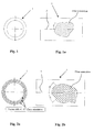
- the composite shank can be constructed with two different technologies, filament winding, as shown in figure 1 , and pultrusion, as shown in figure 2 .
- the best fiber orientation is around 20° with respect to the shank axis A.
- the best lamination sequence is to apply two layers of +/-45°at the outer and inner surfaces of the tube and to manufacture the rest of the tube in uniaxial fibers, as shown in figure 5 .
- the fibers are impregnated in resin which can comprise polyester or vinylester, the latter having a better chemical and mechanical resistance.
- the composite shank has an higher flexibility with respect to the known solutions which comprise a steel shank or a fibreglass moulded shank-blade block.
- conductive reinforcing fibers like carbon fibers, can be inserted in the resin while producing the composite shank.
- the composite shank for axial fan blades has improved flexibility, thus realizing a flexible link between the blade and the fan hub.
- the flexibility of the shank allows to reduce the vibrations consequent to the air load and to the rotational velocity of the fan and transmitted from the blades to the whole structure.
- the composite shank according to the present invention has an improved resistance to chemical attack, thus improving the fan liability also when it is working in aggressive environment.
- a further object achieved by the composite shank for axial fan blades according to the present invention is lighter with respect to the known type of shanks, thus reducing the total weight of the shank-blade block, the bending stress on the shank itself and the vibrations consequent to the fan rotation.
- a further object achieved by the composite shank according to the present invention is to provide a shank for axial fan blades which is suitable to efficiently discharge electrostatic charge, thus fulfilling the requirements of the ATEX norms concerning the safety of the fan when it is working in explosive environment.
- Another object achieved by the present invention is to provide a shank for axial fan blades which has an improved mechanical resistance in particular with respect to mechanical fatigue.
Landscapes
- Engineering & Computer Science (AREA)
- Mechanical Engineering (AREA)
- General Engineering & Computer Science (AREA)
- Structures Of Non-Positive Displacement Pumps (AREA)
Priority Applications (2)
| Application Number | Priority Date | Filing Date | Title |
|---|---|---|---|
| EP07122730A EP2071193A1 (de) | 2007-12-10 | 2007-12-10 | Verbundschaft für Axialgebläseflügel |
| PCT/EP2008/067098 WO2009074568A2 (en) | 2007-12-10 | 2008-12-09 | Composite shank for axial fan blades |
Applications Claiming Priority (1)
| Application Number | Priority Date | Filing Date | Title |
|---|---|---|---|
| EP07122730A EP2071193A1 (de) | 2007-12-10 | 2007-12-10 | Verbundschaft für Axialgebläseflügel |
Publications (1)
| Publication Number | Publication Date |
|---|---|
| EP2071193A1 true EP2071193A1 (de) | 2009-06-17 |
Family
ID=39400982
Family Applications (1)
| Application Number | Title | Priority Date | Filing Date |
|---|---|---|---|
| EP07122730A Withdrawn EP2071193A1 (de) | 2007-12-10 | 2007-12-10 | Verbundschaft für Axialgebläseflügel |
Country Status (2)
| Country | Link |
|---|---|
| EP (1) | EP2071193A1 (de) |
| WO (1) | WO2009074568A2 (de) |
Cited By (2)
| Publication number | Priority date | Publication date | Assignee | Title |
|---|---|---|---|---|
| WO2016075575A1 (en) * | 2014-11-11 | 2016-05-19 | Cofimco S.R.L. | Blade unit for industrial fans |
| CN112969570A (zh) * | 2018-10-30 | 2021-06-15 | 赛峰飞机发动机公司 | 叶片的纤维增强体的纤维的杂化 |
Citations (6)
| Publication number | Priority date | Publication date | Assignee | Title |
|---|---|---|---|---|
| US2918977A (en) * | 1956-06-25 | 1959-12-29 | Koppers Co Inc | Blade assembly |
| GB1165738A (en) * | 1966-11-01 | 1969-10-01 | Cooling Dev Ltd | Improvements in and relating to Fan-Type Impellers and to Blade Assemblies for use therewith |
| FR2427494A1 (fr) * | 1978-06-01 | 1979-12-28 | Neu Sa | Perfectionnement aux pales pour ventilateurs helicoides de tres grand diametre |
| US4884948A (en) * | 1987-03-28 | 1989-12-05 | Mtu Motoren-Und Turbinen Union Munchen Gmbh | Deflectable blade assembly for a prop-jet engine and associated method |
| EP1195527A1 (de) * | 2000-10-05 | 2002-04-10 | Diandra S.A. | Axialüfter |
| US6378322B1 (en) * | 2001-02-28 | 2002-04-30 | General Shelters Of Texas S.B., Ltd. | High-performance molded fan |
-
2007
- 2007-12-10 EP EP07122730A patent/EP2071193A1/de not_active Withdrawn
-
2008
- 2008-12-09 WO PCT/EP2008/067098 patent/WO2009074568A2/en not_active Ceased
Patent Citations (6)
| Publication number | Priority date | Publication date | Assignee | Title |
|---|---|---|---|---|
| US2918977A (en) * | 1956-06-25 | 1959-12-29 | Koppers Co Inc | Blade assembly |
| GB1165738A (en) * | 1966-11-01 | 1969-10-01 | Cooling Dev Ltd | Improvements in and relating to Fan-Type Impellers and to Blade Assemblies for use therewith |
| FR2427494A1 (fr) * | 1978-06-01 | 1979-12-28 | Neu Sa | Perfectionnement aux pales pour ventilateurs helicoides de tres grand diametre |
| US4884948A (en) * | 1987-03-28 | 1989-12-05 | Mtu Motoren-Und Turbinen Union Munchen Gmbh | Deflectable blade assembly for a prop-jet engine and associated method |
| EP1195527A1 (de) * | 2000-10-05 | 2002-04-10 | Diandra S.A. | Axialüfter |
| US6378322B1 (en) * | 2001-02-28 | 2002-04-30 | General Shelters Of Texas S.B., Ltd. | High-performance molded fan |
Cited By (7)
| Publication number | Priority date | Publication date | Assignee | Title |
|---|---|---|---|---|
| WO2016075575A1 (en) * | 2014-11-11 | 2016-05-19 | Cofimco S.R.L. | Blade unit for industrial fans |
| CN107002707A (zh) * | 2014-11-11 | 2017-08-01 | 可风可意大利公司 | 用于工业风扇的叶片单元 |
| US20170314569A1 (en) * | 2014-11-11 | 2017-11-02 | Cofimco S.R.L. | Blade unit for industrial fans |
| CN107002707B (zh) * | 2014-11-11 | 2019-08-13 | 可风可意大利公司 | 用于工业风扇的叶片单元 |
| US10533572B2 (en) * | 2014-11-11 | 2020-01-14 | Cofimco S.R.L. | Blade unit for industrial fans |
| CN112969570A (zh) * | 2018-10-30 | 2021-06-15 | 赛峰飞机发动机公司 | 叶片的纤维增强体的纤维的杂化 |
| CN112969570B (zh) * | 2018-10-30 | 2023-07-07 | 赛峰飞机发动机公司 | 叶片的纤维增强体的纤维的杂化 |
Also Published As
| Publication number | Publication date |
|---|---|
| WO2009074568A2 (en) | 2009-06-18 |
| WO2009074568A3 (en) | 2009-08-27 |
Similar Documents
| Publication | Publication Date | Title |
|---|---|---|
| US3679324A (en) | Filament reinforced gas turbine blade | |
| EP0211279B1 (de) | Mischvorrichtung | |
| EP1798412B1 (de) | Verbindung des Rotorblatts einer Windenergieanlage an eine Rotornabe | |
| US9995271B2 (en) | Wind turbine blade with tapering root bushings | |
| US9541097B1 (en) | Hub assembly for a large cooling fan | |
| US5108262A (en) | High damping flexible propeller/impleller | |
| US8807952B2 (en) | Rotor blade for a wind turbine | |
| CN103717882A (zh) | 风力涡轮机叶片连接器组件 | |
| WO2012140048A2 (en) | Wind turbine blade having a root region with elongated fastening members provided with metal fibres | |
| US20130156585A1 (en) | Method and device for electrical power generation from wind power and method of manufacture thereof | |
| JP6420857B2 (ja) | 風力発電設備、風車翼および風車翼の補強方法 | |
| EP2071193A1 (de) | Verbundschaft für Axialgebläseflügel | |
| US20140030095A1 (en) | Wind turbine blade with elongated fastening members in the root region thereof | |
| CN110626496B (zh) | 一种桨叶根部连接组件 | |
| EP1195527A1 (de) | Axialüfter | |
| WO2024200043A1 (en) | Fan blade for axial flow fan | |
| JPH1122696A (ja) | 軸流ファンのブレード | |
| KR100626759B1 (ko) | 팬 | |
| CN112672876A (zh) | 纤维复合半成品、纤维复合构件、转子叶片元件、转子叶片和风能设施以及用于制造纤维复合半成品的方法和用于制造纤维复合构件的方法 | |
| US20100086408A1 (en) | Fan blade connection | |
| JP2005180265A (ja) | 真空ポンプ | |
| JP2011247245A (ja) | 送風機用羽根車および当該羽根車の製造方法 | |
| CN106625754A (zh) | 多功能大尺寸复合材料机械臂 | |
| CN114483433A (zh) | 用于风能设施的转子轮毂以及相关的转子装置和风能设施 | |
| RU2172434C2 (ru) | Лопасть |
Legal Events
| Date | Code | Title | Description |
|---|---|---|---|
| PUAI | Public reference made under article 153(3) epc to a published international application that has entered the european phase |
Free format text: ORIGINAL CODE: 0009012 |
|
| AK | Designated contracting states |
Kind code of ref document: A1 Designated state(s): AT BE BG CH CY CZ DE DK EE ES FI FR GB GR HU IE IS IT LI LT LU LV MC MT NL PL PT RO SE SI SK TR |
|
| AX | Request for extension of the european patent |
Extension state: AL BA HR MK RS |
|
| 17P | Request for examination filed |
Effective date: 20091216 |
|
| 17Q | First examination report despatched |
Effective date: 20100126 |
|
| AKX | Designation fees paid |
Designated state(s): AT BE BG CH CY CZ DE DK EE ES FI FR GB GR HU IE IS IT LI LT LU LV MC MT NL PL PT RO SE SI SK TR |
|
| STAA | Information on the status of an ep patent application or granted ep patent |
Free format text: STATUS: THE APPLICATION IS DEEMED TO BE WITHDRAWN |
|
| 18D | Application deemed to be withdrawn |
Effective date: 20100806 |