EP2071236A2 - Verfahren für einen Brenner und Brennervorrichtung - Google Patents
Verfahren für einen Brenner und Brennervorrichtung Download PDFInfo
- Publication number
- EP2071236A2 EP2071236A2 EP08171074A EP08171074A EP2071236A2 EP 2071236 A2 EP2071236 A2 EP 2071236A2 EP 08171074 A EP08171074 A EP 08171074A EP 08171074 A EP08171074 A EP 08171074A EP 2071236 A2 EP2071236 A2 EP 2071236A2
- Authority
- EP
- European Patent Office
- Prior art keywords
- oxidant
- burner device
- burner
- supply
- channel
- Prior art date
- Legal status (The legal status is an assumption and is not a legal conclusion. Google has not performed a legal analysis and makes no representation as to the accuracy of the status listed.)
- Withdrawn
Links
Images
Classifications
-
- F—MECHANICAL ENGINEERING; LIGHTING; HEATING; WEAPONS; BLASTING
- F23—COMBUSTION APPARATUS; COMBUSTION PROCESSES
- F23L—SUPPLYING AIR OR NON-COMBUSTIBLE LIQUIDS OR GASES TO COMBUSTION APPARATUS IN GENERAL ; VALVES OR DAMPERS SPECIALLY ADAPTED FOR CONTROLLING AIR SUPPLY OR DRAUGHT IN COMBUSTION APPARATUS; INDUCING DRAUGHT IN COMBUSTION APPARATUS; TOPS FOR CHIMNEYS OR VENTILATING SHAFTS; TERMINALS FOR FLUES
- F23L7/00—Supplying non-combustible liquids or gases, other than air, to the fire, e.g. oxygen, steam
- F23L7/007—Supplying oxygen or oxygen-enriched air
-
- F—MECHANICAL ENGINEERING; LIGHTING; HEATING; WEAPONS; BLASTING
- F23—COMBUSTION APPARATUS; COMBUSTION PROCESSES
- F23C—METHODS OR APPARATUS FOR COMBUSTION USING FLUID FUEL OR SOLID FUEL SUSPENDED IN A CARRIER GAS OR AIR
- F23C7/00—Combustion apparatus characterised by arrangements for air supply
- F23C7/02—Disposition of air supply not passing through burner
- F23C7/06—Disposition of air supply not passing through burner for heating the incoming air
-
- F—MECHANICAL ENGINEERING; LIGHTING; HEATING; WEAPONS; BLASTING
- F23—COMBUSTION APPARATUS; COMBUSTION PROCESSES
- F23L—SUPPLYING AIR OR NON-COMBUSTIBLE LIQUIDS OR GASES TO COMBUSTION APPARATUS IN GENERAL ; VALVES OR DAMPERS SPECIALLY ADAPTED FOR CONTROLLING AIR SUPPLY OR DRAUGHT IN COMBUSTION APPARATUS; INDUCING DRAUGHT IN COMBUSTION APPARATUS; TOPS FOR CHIMNEYS OR VENTILATING SHAFTS; TERMINALS FOR FLUES
- F23L15/00—Heating of air supplied for combustion
- F23L15/02—Arrangements of regenerators
-
- F—MECHANICAL ENGINEERING; LIGHTING; HEATING; WEAPONS; BLASTING
- F23—COMBUSTION APPARATUS; COMBUSTION PROCESSES
- F23D—BURNERS
- F23D14/00—Burners for combustion of a gas, e.g. of a gas stored under pressure as a liquid
-
- F—MECHANICAL ENGINEERING; LIGHTING; HEATING; WEAPONS; BLASTING
- F23—COMBUSTION APPARATUS; COMBUSTION PROCESSES
- F23D—BURNERS
- F23D14/00—Burners for combustion of a gas, e.g. of a gas stored under pressure as a liquid
- F23D14/32—Burners for combustion of a gas, e.g. of a gas stored under pressure as a liquid using a mixture of gaseous fuel and pure oxygen or oxygen-enriched air
-
- F—MECHANICAL ENGINEERING; LIGHTING; HEATING; WEAPONS; BLASTING
- F23—COMBUSTION APPARATUS; COMBUSTION PROCESSES
- F23D—BURNERS
- F23D14/00—Burners for combustion of a gas, e.g. of a gas stored under pressure as a liquid
- F23D14/46—Details
- F23D14/66—Preheating the combustion air or gas
-
- F—MECHANICAL ENGINEERING; LIGHTING; HEATING; WEAPONS; BLASTING
- F23—COMBUSTION APPARATUS; COMBUSTION PROCESSES
- F23L—SUPPLYING AIR OR NON-COMBUSTIBLE LIQUIDS OR GASES TO COMBUSTION APPARATUS IN GENERAL ; VALVES OR DAMPERS SPECIALLY ADAPTED FOR CONTROLLING AIR SUPPLY OR DRAUGHT IN COMBUSTION APPARATUS; INDUCING DRAUGHT IN COMBUSTION APPARATUS; TOPS FOR CHIMNEYS OR VENTILATING SHAFTS; TERMINALS FOR FLUES
- F23L15/00—Heating of air supplied for combustion
- F23L15/04—Arrangements of recuperators
-
- F—MECHANICAL ENGINEERING; LIGHTING; HEATING; WEAPONS; BLASTING
- F23—COMBUSTION APPARATUS; COMBUSTION PROCESSES
- F23L—SUPPLYING AIR OR NON-COMBUSTIBLE LIQUIDS OR GASES TO COMBUSTION APPARATUS IN GENERAL ; VALVES OR DAMPERS SPECIALLY ADAPTED FOR CONTROLLING AIR SUPPLY OR DRAUGHT IN COMBUSTION APPARATUS; INDUCING DRAUGHT IN COMBUSTION APPARATUS; TOPS FOR CHIMNEYS OR VENTILATING SHAFTS; TERMINALS FOR FLUES
- F23L9/00—Passages or apertures for delivering secondary air for completing combustion of fuel
-
- Y—GENERAL TAGGING OF NEW TECHNOLOGICAL DEVELOPMENTS; GENERAL TAGGING OF CROSS-SECTIONAL TECHNOLOGIES SPANNING OVER SEVERAL SECTIONS OF THE IPC; TECHNICAL SUBJECTS COVERED BY FORMER USPC CROSS-REFERENCE ART COLLECTIONS [XRACs] AND DIGESTS
- Y02—TECHNOLOGIES OR APPLICATIONS FOR MITIGATION OR ADAPTATION AGAINST CLIMATE CHANGE
- Y02E—REDUCTION OF GREENHOUSE GAS [GHG] EMISSIONS, RELATED TO ENERGY GENERATION, TRANSMISSION OR DISTRIBUTION
- Y02E20/00—Combustion technologies with mitigation potential
- Y02E20/34—Indirect CO2mitigation, i.e. by acting on non CO2directly related matters of the process, e.g. pre-heating or heat recovery
Definitions
- the present invention relates to a method and a burner device for increasing the efficency during heating of an industrial furnace. More specifically, the invention relates to a so called regenerative burner with improved combustion efficiency.
- the expression "regenerative" burner device is used for a burner device in which the cold oxidant and hot flue gases alternatingly are led through a heat buffer, so that the heat of the flue gases is used for preheating of the oxidant. This increases efficiency during combustion.
- the heat buffer may consist of a pipe partially filled with heat absorbing material, such as balls or a honeycomb structure made from a ceramic or a metal material.
- a commonly used operation scheme involves about 30 seconds of percolation of hot flue gases through the buffer, followed by about 30 seconds of percolation of ambiently tempered oxidant, which oxidant is thereby heated by the heat absorbing material.
- the combustion may be alternated between two or more burners, whereby hot flue gases from the other burners are led out from the furnace through the oxidant channel of one of the burners at a time and through the heat buffer, or one burner may be furnished with several oxidant channels that are used alternatingly to supply oxidant to the burner and carry flue gases out from the furnace.
- Such regenerative burner devices are typically optimised for a specific, high power. This works well for continuous heating, but is problematic for batchwise heating. Namely, batchwise heating of metal material often takes place over two steps, where an introductory, high power step, herein denoted “heating step”, aims at heating the furnace and the surface of the metal material to a predetermined final temperature, and a final, low power step, herein denoted “temperature homogenising step”, aiming at letting the whole metal material assume a predetermined, homogenous temperature profile through heat conduit.
- heating step aims at heating the furnace and the surface of the metal material to a predetermined final temperature
- temperature homogenising step aims at letting the whole metal material assume a predetermined, homogenous temperature profile through heat conduit.
- the heating step may for instance last between 2 and 10 hours, depending on the prerequisites, during which time the burner or burners is or are operated at or near their optimal, high power.
- the temperature homogenising step may correspondingly last between 1 and 40 hours, and involves considerably lower burner powers.
- the furnace temperature is essentially lower than the desired process temperature, why the heat absorbing material in the heat buffer cannot be heated to the temperature which is needed for the burner to reach maximum efficiency.
- regenerative burners being dimensioned for the heating step are at the same time overdimensioned for the temperature homogenisation step, why their power must be adjusted to be lower during this step.
- this may be done by using a so called on/off procedure, in which the burner alternatingly and periodically is turned on or off.
- this leads to that the temperature in the heat buffer decreases during the switched off time, which substantially reduces the efficiency of the burner.
- regenerative burners are often designed with a maximum power which is near that needed during the heating step.
- substantial costs and/or construction changes are needed if an even higher power for some reason is needed at a later time, since regenerative burners are comparatively large and bulky by design, and since each such burner also normally demands correctly dimensioned fan devices for conveying the gases through the heat buffer, which fans therefore also need to be changed.
- the present invention solves the above described problems.
- the invention relates to a burner device for an industrial furnace comprising a channel for fuel, a channel for a first oxidant, an outlet for flue gases, a control device and a heat buffer, where the first oxidant and the flue gases alternatingly are led through the heat buffer, and is characterised in that a separate lancing device is arranged to provide a second oxidant to the burner device.
- the invention relates to a method of the type and with mainly the features as described in claim 11.
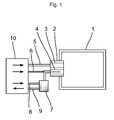
- a regenerative burner device 2 is arranged in an industrial furnace 1 for batchwise heating of metal material. More than one burner device may be arranged inside the furnace 1, depending on the actual application. Especially, burner devices may be arranged in pairs in the industrial furnace 1, whereby such burner pairs may be operated alternatingly.
- the burner device 2 comprises a channel 3 for fuel and a channel 4 for a first oxidant.
- the fuel may be any suitable, gaseous fuel, such as propane or natural gas.
- the first oxidant is for example air, but may also be oxygen enriched air or oxygen gas with an oxygen content of at least 80 percentages by weight.
- the burner device 2 gives rise to a flame (not shown), which is directed into and therefore heats the furnace space.
- the burner device 2 may be of the DFI (Direct Flame Impingement) type, and/or of so called flameless type, whereby a visual flame is missing.
- DFI Direct Flame Impingement
- the burner device 2 comprises a supply conduit 5 for fuel and a supply conduit 8 for the first oxidant.
- the first oxidant is supplied through the supply conduit 8 and into a heat buffer 7, containing a heat absorbing material such as described above, and thereafter on to the channel 4.
- An outled conduit 9 for flue gases also runs from the heat buffer 7.
- the supply conduit 5 for fuel, the supply conduit 8 for the first oxidant and an outlet conduit 9 for flue gases are all connected to a control device 10 that controls the operation of the burner device 2.
- the control device 10 may control the burner device 2 for operation either in combustion mode or in reheating mode.
- combustion mode fuel and the first oxidant are supplied through the conduits 5 and 8, respectively, and the mixture is combusted so that the furnace space is heated.
- reheating mode neither fuel nor the first oxidant are supplied, but flue gases are conveyed out from the furnace space, through the channel 4 for the first oxidant, on to the heat buffer 7 and out through the outlet conduit 9, for subsequent removal.
- the heat absoring material in the heat buffer 7 is heated by the hot flue gases during reaheting mode operation, and the room tempered, first oxidant is preheated by the same material in the heat buffer 7 during combustion mode operation.
- the control device 10 controls the inbound and outbound gas streams in a suitable manner, for instance using a valve arrangement (not shown) and/or suitable, known fans (not shown).
- the burner device 2 may also comprise a separately arranged outlet conduit for flue gases that run out from the furnace space and into the heat buffer 7.
- the control device 10 accomplishes that the burner device 2 is alternated between combustion mode and reheating mode, whereby the thermal energy in the flue gases is recovered for heating of the first oxidant, which increases the combustion efficiency.
- Either one single burner device may be used, which in this case only heats the furnace space when operated in combustion mode, or several burner devices may be used in combination. In the latter case, one or several burner devices may be operated in heating mode and the rest of the burner devices be operated in reheating mode, leading to that the furnace space is heated at all times without interruption.
- all burner devices except one in a burner aggregate are operated in combustion mode, and the last such burner device is operated in reheating mode.
- burner devices are operated in pairs, so that the first device is operated in heating mode at the same time as the second is operated in reheating mode, after which the roles are swapped, and so on.
- burners may share the same heat buffer 7.
- a suitable known valve arrangement is used for conveying the first oxidant through a first channel in the heat buffer 7 to burner devices being operated in heating mode, and at the same time conveying the flue gases from burner devices being operated in reheating mode through a second, separate channel in the heat buffer 7 and out through the outlet conduit 9.
- the first and the second channels are thermally connected, for example by sharing the same heat absorbing material in the form of a common wall or the like.
- a lance 6 which is fed with a second oxidant.
- this second oxidant is comprised of at least 80 percentages by weight oxygen, more preferably at least 95 percentages by weight oxygen.
- Such an elevated concentration of oxygen in the second oxidant leads to, among other things, high combustion efficiency.
- the lance 6 is also connected to, and controlled by, the control device 10.
- a regenerative burner device In a regenerative burner device an important factor, limiting the maximum combustion power, is the amount of preheated oxidant that may be led out through the channel for oxidant 4 per time unit. This depends upon the capacity of the heat buffer 7 as well as on the fact that the heated oxidant has a lower density than cooler oxidant, which results in a larger volume oxidant needed in order to reach the same weight amount. To the contrary, it is comparatively easy to increase the amount of supplied fuel.
- the second oxidant is supplied through the lance 6, one can increase the maximum combustion power without having to in other ways increase the dimensions of the components of the burner device 2, something which would lead to the above described problems with overdimensioning during the temperature homogenising step.
- the second oxidant is supplied at an elevated velocity, preferably a velocity above about 200 m/s, more preferably a velocity which at least amounts to the acoustic velocity.
- the supplied second oxidant also takes part in the combustion reaction, hence resulting in a higher combustion power.
- the amount of the second oxidant which is supplied through the lance 6 may be controlled either by adjusting the size of the orifice of the lance 6 or by adjusting the pressure of the second oxidant being supplied through the lance 6, and may be chosen depending on the purpose of the actual application, in terms of for example combustion power, desired oxygen enrichment and limit amounts for various combustion products such as NO x gases.
- the control may take place continuously during operation, either by a continuous change of the pressure upstream of the lance 6 or according to an on/off procedure, or a single time before the initialisation of a certain operational step.
- the regenerative burner device 2 may be optimised for operation also during a temperature homogenising step, when the power demands are relatively low, which optimisation leads to high efficiency.
- this step little or no second oxidant is supplied through the lance 6. Since the power of the burner device 2 is low at this time, the need for using an on/off procedure for additionally decreasing the power during this step is lessened or disappears completely.
- the second oxidant is supplied through the lance 6 to a comparatively large extent. This results in the combustion power increasing substantially, however with preserved efficiency.
- the additional, second oxidant, supplied at an elevated velocity results in the heating power of the burner device 2 increasing in comparison to conventional, regenerative burner devices 2, which decreases the time necessary for completion of the heating step.
- the amount of the second oxidant that is lanced in the burner device 2 may be controlled in different ways, such as is described above, but the average supplied amount of second oxidant per time unit is less during the temperature homogenising step than during the heating step.
- the present invention achieves a relatively cheap way of substantially broadening the power interval over which high combustion efficiency may be upheld, and at the same time achiveing an increase in the maximum power of the existing combustion device.
- the burner device 2 it is possible to arrange several channels for a first oxidant in the burner device 2. In this case, it is preferred to arrange a lance for a second oxidant in each such channel for the first oxidant. By the help of such an arrangement, a better control over the flame resulting from the burner device may be achieved, and the power of the burner device may be increased. It is also possible to arrange lances for the second oxidant in merely one or only in some of the channels for the first oxidant.
Landscapes
- Engineering & Computer Science (AREA)
- Chemical & Material Sciences (AREA)
- Combustion & Propulsion (AREA)
- Mechanical Engineering (AREA)
- General Engineering & Computer Science (AREA)
- Physics & Mathematics (AREA)
- Thermal Sciences (AREA)
- Air Supply (AREA)
- Pre-Mixing And Non-Premixing Gas Burner (AREA)
- Gas Burners (AREA)
Applications Claiming Priority (1)
| Application Number | Priority Date | Filing Date | Title |
|---|---|---|---|
| SE0702741A SE532339C2 (sv) | 2007-12-10 | 2007-12-10 | Förfarande och anordning vid brännare |
Publications (2)
| Publication Number | Publication Date |
|---|---|
| EP2071236A2 true EP2071236A2 (de) | 2009-06-17 |
| EP2071236A3 EP2071236A3 (de) | 2012-11-28 |
Family
ID=40445554
Family Applications (1)
| Application Number | Title | Priority Date | Filing Date |
|---|---|---|---|
| EP08171074A Withdrawn EP2071236A3 (de) | 2007-12-10 | 2008-12-09 | Verfahren für einen Brenner und Brennervorrichtung |
Country Status (8)
| Country | Link |
|---|---|
| US (2) | US8899970B2 (de) |
| EP (1) | EP2071236A3 (de) |
| JP (1) | JP2009139086A (de) |
| KR (1) | KR20090060941A (de) |
| CN (1) | CN101457930B (de) |
| BR (1) | BRPI0805691A2 (de) |
| RU (1) | RU2008148668A (de) |
| SE (1) | SE532339C2 (de) |
Cited By (4)
| Publication number | Priority date | Publication date | Assignee | Title |
|---|---|---|---|---|
| WO2011101311A1 (en) * | 2010-02-17 | 2011-08-25 | Clean Fuels B.V. | Batch-wise operated retort using temporary storage of heat |
| US20120082946A1 (en) * | 2010-09-30 | 2012-04-05 | Anders Lugnet | Method for carrying out combustion in an industrial furnace |
| WO2017167454A1 (de) * | 2016-03-31 | 2017-10-05 | Linde Aktiengesellschaft | Verfahren zum betreiben eines regenerativbrennersystems und regenerativbrennersystem |
| WO2018148478A1 (en) | 2017-02-13 | 2018-08-16 | Bloom Engineering Company Inc. | Dual mode regenerative burner system and a method of heating a furnace using a dual mode regenerative burner system |
Families Citing this family (2)
| Publication number | Priority date | Publication date | Assignee | Title |
|---|---|---|---|---|
| SE532339C2 (sv) * | 2007-12-10 | 2009-12-15 | Aga Ab | Förfarande och anordning vid brännare |
| EP3242080B1 (de) | 2016-05-04 | 2019-07-10 | WS-Wärmeprozesstechnik GmbH | Vorrichtung und verfahren zur beheizung von öfen mittels strahlrohren |
Family Cites Families (27)
| Publication number | Priority date | Publication date | Assignee | Title |
|---|---|---|---|---|
| US4923391A (en) * | 1984-08-17 | 1990-05-08 | American Combustion, Inc. | Regenerative burner |
| US4874311A (en) * | 1987-08-03 | 1989-10-17 | American Combustion, Inc. | Method and apparatus for improved regenerative furnace |
| US5145361A (en) * | 1984-12-04 | 1992-09-08 | Combustion Research, Inc. | Burner and method for metallurgical heating and melting |
| EP0463218B1 (de) * | 1990-06-29 | 1994-11-23 | Joachim Dr.-Ing. Wünning | Verfahren und Vorrichtung zum Verbrennen von Brennstoff in einem Verbrennungsraum |
| TW278124B (de) * | 1994-10-14 | 1996-06-11 | Toyota Motor Co Ltd | |
| US5664942A (en) * | 1994-10-25 | 1997-09-09 | Abb Air Preheater, Inc. | Regenerative thermal oxidizer |
| JP3460441B2 (ja) * | 1996-04-09 | 2003-10-27 | トヨタ自動車株式会社 | 燃焼装置および該燃焼装置を具備した熱設備 |
| JPH11264667A (ja) | 1998-03-18 | 1999-09-28 | Toho Gas Co Ltd | 回転式溶解炉用の蓄熱式バーナシステム |
| US6113874A (en) * | 1998-04-29 | 2000-09-05 | Praxair Technology, Inc. | Thermochemical regenerative heat recovery process |
| US6176894B1 (en) * | 1998-06-17 | 2001-01-23 | Praxair Technology, Inc. | Supersonic coherent gas jet for providing gas into a liquid |
| US6793486B2 (en) * | 1998-07-30 | 2004-09-21 | Bloom Engineering Company, Inc. | Burner for non-symmetrical combustion and method |
| US6033208A (en) * | 1998-09-11 | 2000-03-07 | Wunning; Joachim | Regenerator burner |
| US6113389A (en) * | 1999-06-01 | 2000-09-05 | American Air Liquide, Inc. | Method and system for increasing the efficiency and productivity of a high temperature furnace |
| JP2001074232A (ja) * | 1999-08-31 | 2001-03-23 | Tokyo Gas Co Ltd | リジェネレイティブバーナにおける蓄熱体支持機構 |
| US20020072020A1 (en) * | 2000-10-16 | 2002-06-13 | Crane John J. | Regnerative burner |
| JP2003194328A (ja) | 2001-12-26 | 2003-07-09 | Tokyo Gas Co Ltd | リジェネレイティブバーナの燃焼方法及びリジェネレイティブバーナ |
| JP3883885B2 (ja) * | 2002-03-04 | 2007-02-21 | 中外炉工業株式会社 | シングルエンド型蓄熱式ラジアントチューブバーナ装置およびその燃焼方法 |
| CN2531250Y (zh) * | 2002-04-05 | 2003-01-15 | 洛阳市隆盛冶金设备有限公司 | 中间罐烘烤器专用煤气燃烧器 |
| ITMI20021526A1 (it) * | 2002-07-11 | 2004-01-12 | Danieli Off Mecc | Iniettore per forni di fusione di materiale metallico |
| JP2004077011A (ja) * | 2002-08-15 | 2004-03-11 | Jfe Steel Kk | 放射加熱装置 |
| SE0202836D0 (sv) * | 2002-09-25 | 2002-09-25 | Linde Ag | Method and apparatus for heat treatment |
| US7416137B2 (en) * | 2003-01-22 | 2008-08-26 | Vast Power Systems, Inc. | Thermodynamic cycles using thermal diluent |
| US7833009B2 (en) | 2004-09-10 | 2010-11-16 | Air Products And Chemicals, Inc. | Oxidant injection method |
| CN101057103B (zh) * | 2004-11-04 | 2011-03-30 | 诺韦利斯公司 | 清洁蓄热式燃烧器介质床的设备和方法 |
| GB2427261A (en) * | 2005-06-17 | 2006-12-20 | Laidlaw Drew Ltd | Fuel Injector for a Glass Melting Furnace |
| US20090130617A1 (en) * | 2007-11-19 | 2009-05-21 | Cain Bruce E | Regenerative burner apparatus |
| SE532339C2 (sv) * | 2007-12-10 | 2009-12-15 | Aga Ab | Förfarande och anordning vid brännare |
-
2007
- 2007-12-10 SE SE0702741A patent/SE532339C2/sv not_active IP Right Cessation
-
2008
- 2008-12-05 KR KR1020080122990A patent/KR20090060941A/ko not_active Ceased
- 2008-12-09 BR BRPI0805691-9A patent/BRPI0805691A2/pt not_active IP Right Cessation
- 2008-12-09 JP JP2008313360A patent/JP2009139086A/ja active Pending
- 2008-12-09 US US12/330,549 patent/US8899970B2/en not_active Expired - Fee Related
- 2008-12-09 EP EP08171074A patent/EP2071236A3/de not_active Withdrawn
- 2008-12-09 RU RU2008148668/06A patent/RU2008148668A/ru not_active Application Discontinuation
- 2008-12-10 CN CN2008101843339A patent/CN101457930B/zh not_active Expired - Fee Related
-
2014
- 2014-03-12 US US14/206,128 patent/US9341369B2/en not_active Expired - Fee Related
Cited By (6)
| Publication number | Priority date | Publication date | Assignee | Title |
|---|---|---|---|---|
| WO2011101311A1 (en) * | 2010-02-17 | 2011-08-25 | Clean Fuels B.V. | Batch-wise operated retort using temporary storage of heat |
| US20120082946A1 (en) * | 2010-09-30 | 2012-04-05 | Anders Lugnet | Method for carrying out combustion in an industrial furnace |
| US9689614B2 (en) * | 2010-09-30 | 2017-06-27 | Linde Aktiengesellschaft | Method for carrying out combustion in an industrial furnace |
| WO2017167454A1 (de) * | 2016-03-31 | 2017-10-05 | Linde Aktiengesellschaft | Verfahren zum betreiben eines regenerativbrennersystems und regenerativbrennersystem |
| WO2018148478A1 (en) | 2017-02-13 | 2018-08-16 | Bloom Engineering Company Inc. | Dual mode regenerative burner system and a method of heating a furnace using a dual mode regenerative burner system |
| EP3580513A4 (de) * | 2017-02-13 | 2020-11-18 | Bloom Engineering Company, Inc. | Regeneratives brennsystem mit zwei modi und verfahren zum heizen eines ofens unter verwendung eines regenerativen brennsystems mit zwei modi |
Also Published As
| Publication number | Publication date |
|---|---|
| EP2071236A3 (de) | 2012-11-28 |
| US8899970B2 (en) | 2014-12-02 |
| CN101457930B (zh) | 2011-02-09 |
| US9341369B2 (en) | 2016-05-17 |
| CN101457930A (zh) | 2009-06-17 |
| BRPI0805691A2 (pt) | 2009-08-25 |
| US20090148799A1 (en) | 2009-06-11 |
| JP2009139086A (ja) | 2009-06-25 |
| SE0702741L (sv) | 2009-06-11 |
| RU2008148668A (ru) | 2010-06-20 |
| SE532339C2 (sv) | 2009-12-15 |
| KR20090060941A (ko) | 2009-06-15 |
| US20140193758A1 (en) | 2014-07-10 |
Similar Documents
| Publication | Publication Date | Title |
|---|---|---|
| US9341369B2 (en) | Method for burner and burner device | |
| EP0877203B1 (de) | Verbrennungsverfahren mit zweifacher Oxidationsmitteleinfuhr | |
| US20090061366A1 (en) | Integration of oxy-fuel and air-fuel combustion | |
| US7232542B2 (en) | Preheating cold blast air of a blast furnace for tempering the hot blast temperature | |
| EP2513345B1 (de) | Verfahren zum erhitzen eines hochofens | |
| CN103562148A (zh) | 熔化装置 | |
| EP2260237B1 (de) | Verfahren für den betrieb eines hochofens | |
| KR101879895B1 (ko) | 용광로 스토브를 가열하기 위한 장치 및 방법 | |
| AU2010200558B2 (en) | Method for homogenizing the heat distribution as well as decreasing the amount of NOx | |
| EA016077B1 (ru) | Способ нагрева в печи с использованием топлива со слабой тепловой мощностью и печь, в которой применяется этот способ | |
| US20090035713A1 (en) | Reheat and tunnel furnace systems with reduced nitrogen oxides emissions | |
| WO2009018476A1 (en) | Reheat and tunnel furnace systems with reduced nitrogen oxides emissions | |
| JP3044286B2 (ja) | 連続焼鈍炉 | |
| EP2743623A1 (de) | Ofen und Verfahren zum Erwärmen einer Atmosphäre in einer Brennkammer eines Ofens | |
| JP6203998B2 (ja) | 加熱装置 | |
| EP2488797B1 (de) | Direktbefeuerter emissionsarmer luftheizer | |
| RU2575890C2 (ru) | Нагревательное устройство | |
| US20230003378A1 (en) | Method and device for heating a furnace |
Legal Events
| Date | Code | Title | Description |
|---|---|---|---|
| PUAI | Public reference made under article 153(3) epc to a published international application that has entered the european phase |
Free format text: ORIGINAL CODE: 0009012 |
|
| AK | Designated contracting states |
Kind code of ref document: A2 Designated state(s): AT BE BG CH CY CZ DE DK EE ES FI FR GB GR HR HU IE IS IT LI LT LU LV MC MT NL NO PL PT RO SE SI SK TR |
|
| AX | Request for extension of the european patent |
Extension state: AL BA MK RS |
|
| PUAL | Search report despatched |
Free format text: ORIGINAL CODE: 0009013 |
|
| AK | Designated contracting states |
Kind code of ref document: A3 Designated state(s): AT BE BG CH CY CZ DE DK EE ES FI FR GB GR HR HU IE IS IT LI LT LU LV MC MT NL NO PL PT RO SE SI SK TR |
|
| AX | Request for extension of the european patent |
Extension state: AL BA MK RS |
|
| RIC1 | Information provided on ipc code assigned before grant |
Ipc: F23D 14/66 20060101AFI20121022BHEP Ipc: F23L 7/00 20060101ALI20121022BHEP Ipc: F23L 15/02 20060101ALI20121022BHEP |
|
| 17P | Request for examination filed |
Effective date: 20130524 |
|
| RBV | Designated contracting states (corrected) |
Designated state(s): AT BE BG CH CY CZ DE DK EE ES FI FR GB GR HR HU IE IS IT LI LT LU LV MC MT NL NO PL PT RO SE SI SK TR |
|
| AKX | Designation fees paid |
Designated state(s): AT BE BG CH CY CZ DE DK EE ES FI FR GB GR HR HU IE IS IT LI LT LU LV MC MT NL NO PL PT RO SE SI SK TR |
|
| RIC1 | Information provided on ipc code assigned before grant |
Ipc: F23D 14/32 20060101ALI20160120BHEP Ipc: F23D 14/66 20060101ALI20160120BHEP Ipc: F23L 15/04 20060101ALI20160120BHEP Ipc: F23L 7/00 20060101ALI20160120BHEP Ipc: F23L 15/02 20060101ALI20160120BHEP Ipc: F23L 9/00 20060101AFI20160120BHEP |
|
| 17Q | First examination report despatched |
Effective date: 20160202 |
|
| STAA | Information on the status of an ep patent application or granted ep patent |
Free format text: STATUS: THE APPLICATION IS DEEMED TO BE WITHDRAWN |
|
| 18D | Application deemed to be withdrawn |
Effective date: 20170701 |