EP2071261A1 - Dispositif de séchage d'objets, en particulier de carrosseries de véhicules peintes - Google Patents
Dispositif de séchage d'objets, en particulier de carrosseries de véhicules peintes Download PDFInfo
- Publication number
- EP2071261A1 EP2071261A1 EP08019984A EP08019984A EP2071261A1 EP 2071261 A1 EP2071261 A1 EP 2071261A1 EP 08019984 A EP08019984 A EP 08019984A EP 08019984 A EP08019984 A EP 08019984A EP 2071261 A1 EP2071261 A1 EP 2071261A1
- Authority
- EP
- European Patent Office
- Prior art keywords
- drying tunnel
- drying
- area
- interior
- inert gas
- Prior art date
- Legal status (The legal status is an assumption and is not a legal conclusion. Google has not performed a legal analysis and makes no representation as to the accuracy of the status listed.)
- Granted
Links
Images


Classifications
-
- F—MECHANICAL ENGINEERING; LIGHTING; HEATING; WEAPONS; BLASTING
- F26—DRYING
- F26B—DRYING SOLID MATERIALS OR OBJECTS BY REMOVING LIQUID THEREFROM
- F26B15/00—Machines or apparatus for drying objects with progressive movement; Machines or apparatus with progressive movement for drying batches of material in compact form
- F26B15/10—Machines or apparatus for drying objects with progressive movement; Machines or apparatus with progressive movement for drying batches of material in compact form with movement in a path composed of one or more straight lines, e.g. compound, the movement being in alternate horizontal and vertical directions
- F26B15/12—Machines or apparatus for drying objects with progressive movement; Machines or apparatus with progressive movement for drying batches of material in compact form with movement in a path composed of one or more straight lines, e.g. compound, the movement being in alternate horizontal and vertical directions the lines being all horizontal or slightly inclined
- F26B15/14—Machines or apparatus for drying objects with progressive movement; Machines or apparatus with progressive movement for drying batches of material in compact form with movement in a path composed of one or more straight lines, e.g. compound, the movement being in alternate horizontal and vertical directions the lines being all horizontal or slightly inclined the objects or batches of materials being carried by trays or racks or receptacles, which may be connected to endless chains or belts
-
- F—MECHANICAL ENGINEERING; LIGHTING; HEATING; WEAPONS; BLASTING
- F26—DRYING
- F26B—DRYING SOLID MATERIALS OR OBJECTS BY REMOVING LIQUID THEREFROM
- F26B21/00—Arrangements for supplying or controlling air or other gases for drying solid materials or objects
- F26B21/40—Arrangements for supplying or controlling air or other gases for drying solid materials or objects using gases other than air
-
- F—MECHANICAL ENGINEERING; LIGHTING; HEATING; WEAPONS; BLASTING
- F26—DRYING
- F26B—DRYING SOLID MATERIALS OR OBJECTS BY REMOVING LIQUID THEREFROM
- F26B25/00—Details of general application not covered by group F26B21/00 or F26B23/00
- F26B25/06—Chambers, containers, or receptacles
- F26B25/08—Parts thereof
-
- F—MECHANICAL ENGINEERING; LIGHTING; HEATING; WEAPONS; BLASTING
- F26—DRYING
- F26B—DRYING SOLID MATERIALS OR OBJECTS BY REMOVING LIQUID THEREFROM
- F26B2210/00—Drying processes and machines for solid objects characterised by the specific requirements of the drying goods
- F26B2210/12—Vehicle bodies, e.g. after being painted
Definitions
- Drying in the present case is understood as any type of curing, regardless of whether it is associated with the expulsion of solvents or is based wholly or partly on a chemical reaction, for example a polymerization or polycondensation.
- an inlet lock area substantially comprises three chambers: a first, which is filled with normal atmosphere and the freshly coated objects are supplied from the coating station.
- a second chamber is partially below the first chamber, is connected thereto via a large-area opening through which the coated articles can be lowered, and contains an inert gas atmosphere whose density is greater than that of the outer normal atmosphere.
- a third lock chamber is in turn above the second lock chamber approximately at the level of the first lock chamber and adjacent to this and is also connected to the second lock chamber via a large-area opening. It also contains an inert gas atmosphere and communicates with the inert gas atmosphere within the drying tunnel. The coated objects are guided through these lock chambers in the order listed.
- a similar, however from the now dried objects in the reverse direction traversed outlet lock area is located at the end of the drying tunnel.
- Object of the present invention is thus to develop a device of the type mentioned so that the costs caused by inert gas consumption during operation are further reduced.
- This object is achieved in that c) inside the drying tunnel at least one replaceable filler body is placed, which fills an unnecessary space area of the drying tunnel.
- residual volumes in the corners of the drying tunnel, adjacent to and above the objects and / or below the conveyor system, are filled with the filling body.
- the inert gas to be filled with the inner volume in the drying tunnel and thus the need for inert gas is minimized.
- a preferred flow direction for the inert gas through the interior and any voids of the objects For example, an interior, a front space and a rear space of a vehicle body, given, whereby the flushing of the interior improves and the inerting is accelerated.
- At least one handling device is arranged in the drying tunnel, which is suitable for acting on the object, in particular to open and close doors, front hood and / or tailgate of the vehicle body, or drying agent, in particular radiation sources for irradiating the surfaces of the objects move.
- all surfaces can optionally also be achieved in cavities of the objects with the drying agent and dried optimally.
- the drying agent can be moved freely in space, in particular also in the cavities of the objects, within the scope of what the handling device permits and can be optimally placed and oriented relative to the surfaces to be dried. Unused space areas outside the movement space of the handling device are filled with the filler (s).
- the shape, size and / or position of the filling body can advantageously be adapted to the type, in particular shape and size, of the object and / or optionally to the space requirement of the handling device.
- a plurality of preferably uniform packing may be placed in the space not required so that they fill as completely as possible.
- Uniform packings can be used flexibly on different types of articles and / or handling equipment. They can simply be arranged as needed in the drying tunnel.
- the filler has at least two rectangular planar surfaces.
- the filler is a cuboid, a cube or a cut cuboid or cube.
- Right-angled flat surfaces can simply be applied without gaps to surfaces of adjacent fillers and / or a wall, a floor and / or a ceiling of the drying tunnel at right angles to one another. Cubes or cubes can be easily stacked. With cut cubes or cubes, space regions can be cut out, through which the objects travel and / or in which any handling devices have an increased space requirement, preferably for moving arms.
- the filler may be solid or a closed hollow body.
- Massive fillers are dimensionally stable and can also be changed in shape, preferably cut to size, even when installed in the drying tunnel. Adjustments in the form of recesses for any handling devices can still be made at the installation site become.
- hollow bodies are lightweight, inexpensive and have a low heat capacity.
- the filler can be arranged on the floor, on at least one wall and / or on the ceiling of the drying tunnel, in particular releasably fixed. In this way unnecessary side and corner areas of the drying tunnel are optimally filled.
- an inlet lock area is provided which is connected upstream of the drying tunnel and separates the inert gas atmosphere prevailing inside the drying tunnel from the outer normal atmosphere.
- an outlet lock region can be provided, which is connected downstream of the drying tunnel and separates the inert gas atmosphere prevailing inside the drying tunnel from the outer normal atmosphere.
- the inert gas loss during insertion or removal of the articles into the drying tunnel or out of it is kept low.
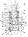
- FIG. 1 shows in horizontal section a drying area of a total provided with the reference numeral 10 paint shop for vehicle bodies 12th
- This drying area comprises an inlet lock area 14 for a drying tunnel 16, the drying tunnel 16 itself and an outlet lock area 18.
- the inlet lock area 14, the drying tunnel 16 and the outlet lock area 18 are cyclically traversed by the vehicle bodies 12 in the direction of the arrow 20, wherein a conveying system 22, which is not described in detail, is used, which is known to the person skilled in the art.
- the illustrated section is preceded by a painting booth, not shown, and preparation stations, which correspond to the prior art; Downstream is a conventional cooling zone.
- While oxygen-containing "normal atmosphere” is located in the paint booth preceded by the drying tunnel 16 and in the cooling zone connected downstream of the drying tunnel, inside the drying tunnel 16 lies an inert gas atmosphere containing, for example, nitrogen and / or CO 2 .
- an inert gas atmosphere containing, for example, nitrogen and / or CO 2 .
- the piston lock 19 is in the Figures 2 . 3 and 7 shown. The operation of the lock areas 14 and 18 is not of interest here.
- the vehicle bodies 12 pass through the drying tunnel 16 in the conveying direction 20 immediately behind the inlet lock area 14 initially a top dry area 24, in which the paint outside on the roofs, the front hoods 12b and the tailgate 12a of the vehicle bodies 12 and at the substantially perpendicular to Conveying direction is cured with vertical component extending surfaces in the front and rear.
- the top drying section 24 is in the FIG. 4 shown in a vertical section transverse to the conveying direction 20 and described in more detail below.
- the top dry area 24 is followed by a side dry area 26 of the drying tunnel 16 where the paint on the outside of the vehicle and the doors 12c and 12d are cured.
- a vertical section of the side drying area 26 transversely to the conveying direction 20 shows the FIG. 5 , on the basis of which a more detailed description is given below.
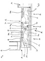
- an interior dry area 28 of the drying tunnel 16 In the conveying direction 20 behind the side drying area 26 is an interior dry area 28 of the drying tunnel 16. In the interior dry area 28, the curing of the paint and the paint overspray in the interior, in the rear compartment and in the front of the vehicle bodies 12 and in an angular area the door, rear room and front room openings. Vertical sections of the interior drying area 28 transverse to the conveying direction approximately in the middle and in the vicinity of the outlet lock area 18 are in the FIGS. 6 and 7 shown, which are used below for a more detailed description.
- the upper side drying area 24 is tapered in a region adjacent to the inlet lock area 14 in the horizontal dimension transverse to the conveying direction 20 with respect to the remaining drying tunnel 16 in order to minimize the inner volume of the drying tunnel 16 and thus the demand for inert gas ,
- a bridge portal 30 is displaceable in and against the conveying direction 20 on two parallel floor rails 32.
- the bridge portal 30 is a total of approximately U-shaped and open at the bottom (see. FIG. 4 ). It is dimensioned so that the vehicle bodies 12 can drive under it.
- the paint applied in the paint booth and the paint overspray on the surfaces of the vehicle bodies 12 can be cured.
- a side irradiation device 42 is provided, which in a vertical section transverse to the conveying direction 20 in FIG. 5 is shown.
- the side irradiation device 42 comprises, in the conveying direction 20 on both sides of the conveying path of the vehicle bodies 12, in each case a radiator frame 44, which carries in each case three UV radiators 36b.
- the radiator frames 44 are identical and arranged symmetrically with respect to a parallel to the conveying direction 20 extending vertical center plane on opposite sides of the conveying path of the vehicle bodies 12.
- the radiator frames 44 each have a horizontal base frame 44a, on the bottom of four rollers 44b are arranged and with which the radiator frames 44 on horizontal bottom rails 46 are transversely displaceable to the conveying direction 20.
- Each UV emitter 36b may be aligned substantially parallel to the lateral surfaces of the vehicle bodies 12 for optimum illumination.
- a tailgate opener 50 In the interior drying area 28 is adjacent to the side drying area 26 on the right in the conveying direction 20 side of the vehicle bodies 12, a tailgate opener 50. With the tailgate opener 50, the tailgate 12a of the vehicle body 12 can be opened in not interesting further here ,
- the liftgate opener 50 is constructed similar to a bonnet opener 150 which is shown in FIG FIG. 7 is shown and with which the front hood 12 b of the vehicle body 12 can be opened.
- the bonnet opener 150 is located on the same side of the vehicle body conveyance path 12 as the tailgate opener 50. It is viewed in the direction of conveyance 20 at the end of the drying tunnel 16 in FIG Near the outlet lock area 18 also attached to the ground.
- the tailgate opener 50 and the bonnet opener 150 each include a handling device 52 and 152, respectively.
- the handling devices 52 and 152 each have a pivoting arm 58 or 158, which are pivotable within a respective pivoting space in the drying tunnel 16.
- the terminal interior irradiation devices 60 are constructed identically and serve for irradiating the inner surfaces of the front space or the rear space with UV light.
- the front interior irradiation device 60 is also in the FIG. 7 shown.
- Each terminal interior irradiation device 60 has a handling device 62 which is rotatably attached to the bottom of the drying tunnel 16. With the respective handling device 62, a in FIG. 1 shown cylindrical tubular UV radiator 36 c moved into the front and in the rear compartment and aligned there as needed.
- the handling device 62 has a three-part pivot arm 66, which is particularly good in the FIG. 1 is recognizable.
- the pivot arm 66 carries at its free end the UV lamp 36c.
- door openers 70 for the front doors 12c and the rear doors 12d are arranged on both sides of the conveying path for the vehicle bodies 12.
- the door openers 70 are identical.
- the two door openers 70 for the rear doors 12d are in FIG. 6 shown in vertical section.
- Each door opener 70 has a handling device 72 with a three-part pivot arm 76.
- the handling device 72 is attached to the bottom of the drying tunnel 16.
- the UV lamps 36d can, as in the FIGS. 1 and 6 shown with the doors open 12c, 12d are inserted through the door openings in the interior of the vehicle body 12 to irradiate the surfaces there.
- the sake of clarity are in the FIG. 1 the components of the lateral interior Bestrahl Rheinen 80, which are located in the interior, shown in the foreground, although these are actually hidden in the local perspective by the roof or the struts of the roof of the vehicle body 12.
- the indoor irradiation devices 80 are constructed identically.
- the interior trim devices 80 associated with the rear doors 12d are shown in FIGS FIG. 6 shown in vertical section.
- the interior irradiation devices 80 each have a handling device 82 with a three-part swivel arm 86, which carries and can move the UV emitter 36d.
- the handling device 82 is rotatably mounted on the ceiling of the drying tunnel 16 about a vertical first axis.
- the UV lamps 36d can be easily inserted through the open doors 12c, 12d into the interior of the vehicle body 12 and moved there as needed, similar to what happens in the paint booth with the application equipment used there for interior painting.
- the side walls of the drying tunnel 16 have in the upper-side drying area 24 and in the interior drying area 28 each one in FIG. 1 shown door 88 through which the drying tunnel 16 is accessible.
- a plurality of interchangeable packing bodies 90 are additionally placed, which fill out unused space areas of the drying tunnel 16. In this way, the internal volume of the drying tunnel 16 is kept as low as possible in order to reduce the need for inert gas.
- the shape, size and position of the unnecessary room areas depend on the type, in particular shape and size, of the vehicle body 12 by the space requirements of the handling devices 52, 62, 72, 82, the radiator frame 44 and the bridge portal 30.
- the filler 90 can be adjusted accordingly positioned in the interior of the drying tunnel 16.
- the specially adapted cuboid filling bodies 90b are placed on the radiator stands 44 (cf. FIGS. 1 and 5 ).
- the filler plate 90d in the top drying section 24 leaves out the space in which the bridge gantry 30 is movable.
- the packing plate 90d is additionally chamfered.
- the sides of the packing plates 90g and 90h located above the liftgate opener 50 and the bonnet opener 150 are also chamfered so that the openers 50 and 150, the bonnet 12b and the liftgate 12a are not limited in their freedom of movement.
- the filler plate 90h has in the region of the suspension of the lateral interior Bestrahll Rheinen 80 further corresponding recesses 92 (see. Figures 2 . 3 and 6 ).
- cubic filling bodies 90a are stacked on the side walls of the drying tunnel 16 on the bottom on the side drying section 26 facing on both sides of the conveying path in a different arrangement to the local space conditions (see. FIG. 1 ).
- the filler bodies 90c have the shape of cuboids bisected along a diagonal cutting plane.
- the pointed edges of the tapered packing 90c are directed downward (see. FIGS. 1 and 6 ).
- the chamfered packing 90c are specially adapted to the type of the vehicle bodies 12 and the swivel space requirement of the interior side lightening devices 80 and the door opener 70.
- a single block-shaped filling body 90e is arranged, which extends over the entire height of the drying tunnel 16 (cf. FIGS. 1 and 7 ).
- the block-shaped filling body 90e is specially adapted to this position in the drying tunnel 16. It has a recess 94 for the bonnet opener 150.
- a tapered filling body 90f in the form of an irregular tetrahedron is fastened in the conveying direction 20 left rear corner of the drying tunnel 16 below the ceiling of the drying tunnel 16 at the local side wall.
- the tip of the packing 90f faces downward so that the lower portion of the drying tunnel 16 remains free so as not to hinder the freedom of movement of the terminal interior space irradiation device 60 for the front space of the vehicle body 12.
Landscapes
- Engineering & Computer Science (AREA)
- Mechanical Engineering (AREA)
- General Engineering & Computer Science (AREA)
- Drying Of Solid Materials (AREA)
- Coating Apparatus (AREA)
Applications Claiming Priority (1)
| Application Number | Priority Date | Filing Date | Title |
|---|---|---|---|
| DE102007060104A DE102007060104A1 (de) | 2007-12-13 | 2007-12-13 | Vorrichtung zum Trocknen von Gegenständen, insbesondere lackierten Fahrzeugkarosserien |
Publications (2)
| Publication Number | Publication Date |
|---|---|
| EP2071261A1 true EP2071261A1 (fr) | 2009-06-17 |
| EP2071261B1 EP2071261B1 (fr) | 2011-02-23 |
Family
ID=40439401
Family Applications (1)
| Application Number | Title | Priority Date | Filing Date |
|---|---|---|---|
| EP08019984A Not-in-force EP2071261B1 (fr) | 2007-12-13 | 2008-11-17 | Dispositif de séchage d'objets, en particulier de carrosseries de véhicules peintes |
Country Status (2)
| Country | Link |
|---|---|
| EP (1) | EP2071261B1 (fr) |
| DE (2) | DE102007060104A1 (fr) |
Cited By (5)
| Publication number | Priority date | Publication date | Assignee | Title |
|---|---|---|---|---|
| WO2011101316A1 (fr) * | 2010-02-22 | 2011-08-25 | Dürr Systems GmbH | Sas pour transférer une pièce entre un espace extérieur et un espace intérieur d'une zone de traitement de pièce |
| WO2011116861A1 (fr) * | 2010-03-23 | 2011-09-29 | Eisenmann Ag | Installation pour appliquer un revêtement sur des objets et pour durcir le revêtement au moyen d'un rayonnement électromagnétique |
| EP2375205A3 (fr) * | 2010-04-10 | 2017-11-15 | Eisenmann SE | Structure de transport pour le transport d'un objet à l'aide d'une installation de séchage, procédé de séchage d'un revêtement sur un objet et utilisation d'une structure de transport associée |
| IT201900002657A1 (it) * | 2019-02-25 | 2020-08-25 | Cefla Soc Cooperativa | Apparato e metodo per l’essiccazione/polimerizzazione di prodotti chimici |
| WO2020174349A1 (fr) * | 2019-02-25 | 2020-09-03 | Cefla Societa' Cooperativa | Appareil et procédé pour le séchage/durcissement de produits chimiques |
Citations (6)
| Publication number | Priority date | Publication date | Assignee | Title |
|---|---|---|---|---|
| US3196554A (en) * | 1959-06-30 | 1965-07-27 | Fan Air Systems Inc | Apparatus comprising baffles and inflatable air foils for drying lumber |
| US5050314A (en) * | 1988-10-31 | 1991-09-24 | Leon Breckenridge | Method for regulating drying kiln air flow |
| US6696367B1 (en) * | 2002-09-27 | 2004-02-24 | Asm America, Inc. | System for the improved handling of wafers within a process tool |
| DE102004025525B3 (de) | 2004-05-25 | 2005-12-08 | Eisenmann Maschinenbau Gmbh & Co. Kg | Verfahren und Vorrichtung zum Trocknen von Gegenständen, insbesondere von lackierten Fahrzeugkarosserien |
| DE102004025526A1 (de) * | 2004-05-25 | 2005-12-29 | Eisenmann Maschinenbau Gmbh & Co. Kg | Vorrichtung zum Trocknen von Gegenständen, insbesondere von lackierten Fahrzeugkarosserien |
| DE102007018918B3 (de) * | 2007-04-19 | 2008-05-15 | Eisenmann Anlagenbau Gmbh & Co. Kg | Vorrichtung zum Trocknen von Gegenständen, insbesondere von lackierten Fahrzeugkarosserien |
Family Cites Families (1)
| Publication number | Priority date | Publication date | Assignee | Title |
|---|---|---|---|---|
| DE102004029667A1 (de) * | 2003-09-04 | 2005-04-07 | Cetelon Lackfabrik Walter Stier Gmbh & Co.Kg | Verfahren und Vorrichtung zur Härtung einer strahlenhärtbaren Beschichtung sowie Bestrahlungskammer |
-
2007
- 2007-12-13 DE DE102007060104A patent/DE102007060104A1/de not_active Ceased
-
2008
- 2008-11-17 DE DE502008002660T patent/DE502008002660D1/de active Active
- 2008-11-17 EP EP08019984A patent/EP2071261B1/fr not_active Not-in-force
Patent Citations (6)
| Publication number | Priority date | Publication date | Assignee | Title |
|---|---|---|---|---|
| US3196554A (en) * | 1959-06-30 | 1965-07-27 | Fan Air Systems Inc | Apparatus comprising baffles and inflatable air foils for drying lumber |
| US5050314A (en) * | 1988-10-31 | 1991-09-24 | Leon Breckenridge | Method for regulating drying kiln air flow |
| US6696367B1 (en) * | 2002-09-27 | 2004-02-24 | Asm America, Inc. | System for the improved handling of wafers within a process tool |
| DE102004025525B3 (de) | 2004-05-25 | 2005-12-08 | Eisenmann Maschinenbau Gmbh & Co. Kg | Verfahren und Vorrichtung zum Trocknen von Gegenständen, insbesondere von lackierten Fahrzeugkarosserien |
| DE102004025526A1 (de) * | 2004-05-25 | 2005-12-29 | Eisenmann Maschinenbau Gmbh & Co. Kg | Vorrichtung zum Trocknen von Gegenständen, insbesondere von lackierten Fahrzeugkarosserien |
| DE102007018918B3 (de) * | 2007-04-19 | 2008-05-15 | Eisenmann Anlagenbau Gmbh & Co. Kg | Vorrichtung zum Trocknen von Gegenständen, insbesondere von lackierten Fahrzeugkarosserien |
Cited By (5)
| Publication number | Priority date | Publication date | Assignee | Title |
|---|---|---|---|---|
| WO2011101316A1 (fr) * | 2010-02-22 | 2011-08-25 | Dürr Systems GmbH | Sas pour transférer une pièce entre un espace extérieur et un espace intérieur d'une zone de traitement de pièce |
| WO2011116861A1 (fr) * | 2010-03-23 | 2011-09-29 | Eisenmann Ag | Installation pour appliquer un revêtement sur des objets et pour durcir le revêtement au moyen d'un rayonnement électromagnétique |
| EP2375205A3 (fr) * | 2010-04-10 | 2017-11-15 | Eisenmann SE | Structure de transport pour le transport d'un objet à l'aide d'une installation de séchage, procédé de séchage d'un revêtement sur un objet et utilisation d'une structure de transport associée |
| IT201900002657A1 (it) * | 2019-02-25 | 2020-08-25 | Cefla Soc Cooperativa | Apparato e metodo per l’essiccazione/polimerizzazione di prodotti chimici |
| WO2020174349A1 (fr) * | 2019-02-25 | 2020-09-03 | Cefla Societa' Cooperativa | Appareil et procédé pour le séchage/durcissement de produits chimiques |
Also Published As
| Publication number | Publication date |
|---|---|
| DE502008002660D1 (de) | 2011-04-07 |
| EP2071261B1 (fr) | 2011-02-23 |
| DE102007060104A1 (de) | 2009-06-18 |
Similar Documents
| Publication | Publication Date | Title |
|---|---|---|
| EP2071260A1 (fr) | Dispositif de séchage d'objets, en particulier de carrosseries de véhicules peintes | |
| EP2118603B1 (fr) | Dispositif destiné au séchage d'objets, en particulier de carrosseries de véhicules mises en peinture | |
| EP2071261B1 (fr) | Dispositif de séchage d'objets, en particulier de carrosseries de véhicules peintes | |
| DE102008005582B3 (de) | Vorrichtung zum Trocknen von Gegenständen, insbesondere von lackierten Fahrzeugkarosserien | |
| DE102004025525B3 (de) | Verfahren und Vorrichtung zum Trocknen von Gegenständen, insbesondere von lackierten Fahrzeugkarosserien | |
| EP2083235B1 (fr) | Dispositif de séchage d'objets, en particulier de carrosseries de véhicule peintes | |
| DE10354165B3 (de) | Vorrichtung und Verfahren zur Aushärtung einer Beschichtung in einem Schutzgas | |
| EP2595760B1 (fr) | Unité de traitement et installation de traitement des surfaces d'objets | |
| DE102004023537B4 (de) | Vorrichtung zur Aushärtung einer aus einem Material, das unter elektromagnetischer Strahlung aushärtet, insbesondere aus einem UV-Lack oder aus einem thermisch aushärtenden Lack, bestehenden Beschichtung eines Gegenstandes | |
| EP1651359A2 (fr) | Dispositif pour faire durcir un revetement, constitue d'un materiau durcissant par rayonnement electromagnetique, notamment d'une peinture uv ou d'une peinture a durcissement thermique, d'un objet | |
| DE3419028A1 (de) | Verfahren zum reinigen von koerpern mit luftstrahlen und vorrichtung zur durchfuehrung des verfahrens | |
| EP1649229B1 (fr) | Dispositif pour faire durcir un revetement, constitue d'un materiau durcissant par rayonnement electromagnetique, notamment d'une peinture uv ou d'une peinture a durcissement thermique, d'un objet | |
| DE19645262A1 (de) | Pulver-Sprühbeschichtungskabine | |
| DE102010014489B3 (de) | Transportgestell zum Fördern eines Gegenstandes durch eine Trocknungsanlage, Verfahren zum Trocknen einer Beschichtung auf einem Gegenstand und Verwendung eines Transportgestells hierzu | |
| WO2011101316A1 (fr) | Sas pour transférer une pièce entre un espace extérieur et un espace intérieur d'une zone de traitement de pièce | |
| DE20002002U1 (de) | Verschiebbare Trennwand für einen begehbaren Kühlraum | |
| DE102004023538B4 (de) | Vorrichtung zur Aushärtung einer aus einem Material, das unter elektromagnetischer Strahlung aushärtet, insbesondere aus einem UV-Lack oder thermisch aushärtendem Lack bestehenden Beschichtung eines Gegenstandes | |
| DE102004025526B4 (de) | Vorrichtung zum Trocknen von Gegenständen, insbesondere von lackierten Fahrzeugkarosserien | |
| EP3261806B1 (fr) | Dispositif pour le traitement d'objets | |
| DE102004040161A1 (de) | Vorrichtung zum Beschichten, insbesondere zum Lackieren, von Gegenständen, insbesondere von Fahrzeugkarosserien | |
| EP1331038B1 (fr) | Dispositif pour le traitement de pièces | |
| DE3134248A1 (de) | "verschliessbare kabine, insbesondere zum spritzen von farben, lacken u. dgl." | |
| EP1258693B1 (fr) | Procédé et dispositif pour le séchage de bois de sciage | |
| EP1656998A1 (fr) | Cabine de pulvérisation de poudre | |
| EP2550497B1 (fr) | Installation pour appliquer un revetement sur des objets et pour durcir le revetement au moyen d'un rayonnement electromagnetique |
Legal Events
| Date | Code | Title | Description |
|---|---|---|---|
| PUAI | Public reference made under article 153(3) epc to a published international application that has entered the european phase |
Free format text: ORIGINAL CODE: 0009012 |
|
| AK | Designated contracting states |
Kind code of ref document: A1 Designated state(s): AT BE BG CH CY CZ DE DK EE ES FI FR GB GR HR HU IE IS IT LI LT LU LV MC MT NL NO PL PT RO SE SI SK TR |
|
| AX | Request for extension of the european patent |
Extension state: AL BA MK RS |
|
| AKX | Designation fees paid | ||
| 17P | Request for examination filed |
Effective date: 20090710 |
|
| RBV | Designated contracting states (corrected) |
Designated state(s): DE FR IT SE |
|
| GRAP | Despatch of communication of intention to grant a patent |
Free format text: ORIGINAL CODE: EPIDOSNIGR1 |
|
| GRAS | Grant fee paid |
Free format text: ORIGINAL CODE: EPIDOSNIGR3 |
|
| GRAA | (expected) grant |
Free format text: ORIGINAL CODE: 0009210 |
|
| RAP1 | Party data changed (applicant data changed or rights of an application transferred) |
Owner name: EISENMANN AG |
|
| AK | Designated contracting states |
Kind code of ref document: B1 Designated state(s): DE FR IT SE |
|
| REF | Corresponds to: |
Ref document number: 502008002660 Country of ref document: DE Date of ref document: 20110407 Kind code of ref document: P |
|
| REG | Reference to a national code |
Ref country code: DE Ref legal event code: R096 Ref document number: 502008002660 Country of ref document: DE Effective date: 20110407 |
|
| REG | Reference to a national code |
Ref country code: SE Ref legal event code: TRGR |
|
| PLBE | No opposition filed within time limit |
Free format text: ORIGINAL CODE: 0009261 |
|
| STAA | Information on the status of an ep patent application or granted ep patent |
Free format text: STATUS: NO OPPOSITION FILED WITHIN TIME LIMIT |
|
| 26N | No opposition filed |
Effective date: 20111124 |
|
| REG | Reference to a national code |
Ref country code: DE Ref legal event code: R097 Ref document number: 502008002660 Country of ref document: DE Effective date: 20111124 |
|
| REG | Reference to a national code |
Ref country code: DE Ref legal event code: R082 Ref document number: 502008002660 Country of ref document: DE Representative=s name: OSTERTAG & PARTNER, PATENTANWAELTE MBB, DE Ref country code: DE Ref legal event code: R081 Ref document number: 502008002660 Country of ref document: DE Owner name: EISENMANN SE, DE Free format text: FORMER OWNER: EISENMANN AG, 71032 BOEBLINGEN, DE |
|
| REG | Reference to a national code |
Ref country code: FR Ref legal event code: PLFP Year of fee payment: 8 |
|
| REG | Reference to a national code |
Ref country code: FR Ref legal event code: PLFP Year of fee payment: 9 |
|
| REG | Reference to a national code |
Ref country code: FR Ref legal event code: PLFP Year of fee payment: 10 |
|
| PGFP | Annual fee paid to national office [announced via postgrant information from national office to epo] |
Ref country code: DE Payment date: 20171121 Year of fee payment: 10 Ref country code: FR Payment date: 20171121 Year of fee payment: 10 |
|
| PGFP | Annual fee paid to national office [announced via postgrant information from national office to epo] |
Ref country code: IT Payment date: 20171124 Year of fee payment: 10 Ref country code: SE Payment date: 20171120 Year of fee payment: 10 |
|
| REG | Reference to a national code |
Ref country code: DE Ref legal event code: R119 Ref document number: 502008002660 Country of ref document: DE |
|
| REG | Reference to a national code |
Ref country code: SE Ref legal event code: EUG |
|
| PG25 | Lapsed in a contracting state [announced via postgrant information from national office to epo] |
Ref country code: SE Free format text: LAPSE BECAUSE OF NON-PAYMENT OF DUE FEES Effective date: 20181118 |
|
| PG25 | Lapsed in a contracting state [announced via postgrant information from national office to epo] |
Ref country code: DE Free format text: LAPSE BECAUSE OF NON-PAYMENT OF DUE FEES Effective date: 20190601 Ref country code: IT Free format text: LAPSE BECAUSE OF NON-PAYMENT OF DUE FEES Effective date: 20181117 Ref country code: FR Free format text: LAPSE BECAUSE OF NON-PAYMENT OF DUE FEES Effective date: 20181130 |