EP2071363A2 - Barrière lumineuse et son procédé de fonctionnement - Google Patents
Barrière lumineuse et son procédé de fonctionnement Download PDFInfo
- Publication number
- EP2071363A2 EP2071363A2 EP08017078A EP08017078A EP2071363A2 EP 2071363 A2 EP2071363 A2 EP 2071363A2 EP 08017078 A EP08017078 A EP 08017078A EP 08017078 A EP08017078 A EP 08017078A EP 2071363 A2 EP2071363 A2 EP 2071363A2
- Authority
- EP
- European Patent Office
- Prior art keywords
- transmitter
- pulses
- synchronization
- pulse
- light grid
- Prior art date
- Legal status (The legal status is an assumption and is not a legal conclusion. Google has not performed a legal analysis and makes no representation as to the accuracy of the status listed.)
- Granted
Links
Images


Classifications
-
- G—PHYSICS
- G01—MEASURING; TESTING
- G01V—GEOPHYSICS; GRAVITATIONAL MEASUREMENTS; DETECTING MASSES OR OBJECTS; TAGS
- G01V8/00—Prospecting or detecting by optical means
- G01V8/10—Detecting, e.g. by using light barriers
- G01V8/20—Detecting, e.g. by using light barriers using multiple transmitters or receivers
Definitions
- the invention relates to a light grid and a method for operating a light grid.
- the light grid has a transmitter unit and a receiver unit for monitoring a planar monitoring area, which are arranged on opposite edges of the monitored area.
- the transmitter unit has an array of side-by-side transmitters emitting transmit light beams.
- the receiver unit has an array of juxtaposed receivers.
- Each transmitter is assigned a receiver for forming a beam axis. When the beam path is free, the receivers are exposed to the transmitted light beams emitted by the respective associated transmitter. If an object is located in the beam path, the beam path of the transmitted light beams of at least one transmitter is interrupted so that they no longer impinge on the associated receiver or the associated receivers, whereby an object detection signal is generated.
- the transmitters and receivers of the individual beam axes are activated cyclically one after the other.
- the synchronization of the transmitter and the receiver takes place optically.
- the transmitter of the first beam axis emits transmitted light beams with a specific identifier.
- the remaining transmitters emit transmit light beams each having an identical identifier that differs from the identifier of the first transmitter.
- the identifier of the first transmitter is that of these four transmitted light pulses while the remaining transmitters emit two transmit light pulses.
- the identifier of the first transmitter which differs from the identifier of the remaining transmitters, can be used to optically synchronize the transmitters and the receivers.
- the DE 10 2005 056 000 A1 describes a light grid having a transmitter unit with a plurality of transmitting elements and a receiver unit with a plurality of receiving elements which form a plurality of cooperating pairs, each consisting of a transmitting element and a receiving element.
- a transmitter control as well as a receiver evaluation unit, the pairs can be cyclically activated one after the other in time for transmitting and for this synchronous receiving of transmission pulses.
- the transmitter control and the receiver evaluation unit are electrically decoupled from each other.
- the transmitter control is designed for each cycle for transmitting exactly one transmission pulse per transmission element.
- the transmitter controller outputs a first synchronization pause after a first transmission pulse for a transmission element in the cycle.
- the transmitter control gives a second synchronization pause after a second transmission pulse with a different duration to the first synchronization pause.
- the receiver evaluation unit can be synchronized in response to the first and second synchronization pause in the cycle to this first and / or second synchronization pause. All transmit pulses have the same duration and shape.
- a disadvantage of this light grid is that due to the evaluation of synchronization pauses between the transmission of transmission pulses by two transmitting elements always more of beam axes, each consisting of a pair of transmitting and receiving element, must be used for synchronization. If only one of these required for synchronization beam axes is permanently blocked by an object intervention, a synchronization of the light grid is no longer possible.
- the invention has for its object to provide a light grid with improved functionality.
- the method according to the invention serves to operate a light grid with a transmitter unit having a number of transmit light beams and with a receiver unit electrically decoupled from the transmitter unit and having a number of receivers, one transmitter each with a receiver forming a beam axis and the transmitters and receivers of the receiver unit individual beam axes for detecting objects in a surveillance area are cyclically activated one after the other.
- An activated transmitter emits transmitted light beams in the form of pulses forming at least one pulse group, the synchronization of all beam axes of the light grid taking place on the basis of a beam axis.
- the pulses emitted by the transmitter of this beam axis differ with respect to at least one parameter in the form of the widths of the pulses or in the form of the pauses or distances between the pulses from the pulses of the further beam axes.
- all transmitters emit pulse groups which consist of several pulses.
- each transmitter can also emit multiple pulse groups.
- At least the transmitter of one beam axis can be differentiated from all other transmitters of the light grid, in that the pauses or distances between the individual pulses or the individual pulse groups of this transmitter differ from the corresponding parameters of the remaining transmitters, so that on the basis of this respective unique characteristic
- This beam axis can be used to synchronize the light grid.
- all transmitters emit only a single pulse when they are activated.
- the transmitter of the beam axis used for synchronization emits a pulse whose length differs from the pulses emitted by the remaining transmitters.
- the beam axis whose transmitter emits pulses with the individual pulse length, distinguishable from all others and can be used for synchronization. Since the transmitters of all beam axes emit only individual pulses and no additional synchronization pauses are required for synchronization, the control of the transmitters can be carried out with a low hardware outlay. In addition, there is a short cycle time in the cyclic activation of the individual beam axes.
- an essential aspect is that this, in particular when used in safety applications, has a high availability, since already a beam axis is sufficient to synchronize the light grid.
- the light grid In safety applications, the light grid is used in particular for the purposes of personal protection, the light grid is used to monitor safety-critical areas on machinery or equipment.
- safety-relevant object interventions such as the entry of a person into the safety-critical area, must be reliably detected, so that a shutdown command for the machine to be monitored is generated by the object detection signal generated in the light grid in order to be able to exclude hazards for the respective person.
- the entire monitoring area covered by the light grid can form such a safety-critical area.
- subregions of the monitored area covered by the light grid can not always form safety-critical areas, because non-safety-critical objects such as machine parts or conveyor units, for example, penetrate into these areas.
- non-safety-critical objects such as machine parts or conveyor units, for example, penetrate into these areas.
- non-safety-relevant areas of the monitored area covered by the light grid can be masked out by means of a so-called blanking or muting method.
- a so-called blanking or muting method In the beam axes of the light grid, which form the blanked areas, an interruption of the transmitted light beams by an object intervention does not lead to a shutdown command for the machine. Only when an object enters an area of the light grid which is not hidden, the interruption of a beam axis in this area leads to a switch-off command for the machine.
- Such blanking and muting methods can considerably increase the availability of the machine monitored by the light grid.
- one or more beam axes can be permanently interrupted by an object engagement. If now just these beam axes are needed for synchronization, an operation of the light grid is no longer possible because these beam axes can not be used for synchronization.
- the probability that one of these beam axes falls into a blanked out area and thus be permanently interrupted is relatively high.
- already one beam axis is sufficient for synchronization, so that the probability that this beam axis falls into a blanked-out area is correspondingly lower.
- the risk that the light grid is not synchronized, reduced accordingly, that is, the availability of the light grid is increased.
- the availability of the light grid according to the invention can be significantly increased if a plurality of beam axes are provided whose emitters emit pulse groups which differ in at least one characteristic and for the synchronization of the light grid optionally at least one of these beam axes is used.
- the transmitters of the beam axes are activated one after the other and the synchronization takes place on the basis of the first free beam axis whose transmitter emits a pulse group with a unique identifier.
- the synchronization of the light grid is no longer fixed to a beam axis, but is used for synchronization in the light grid automatically from a number of suitable for synchronization beam axes, the first free beam axis for synchronization.
- the pulses used for synchronization that is pulse sequences of at least one pulse group, successively impressed on the transmitters of different beam axes, so that these transmitters transmit light beams Emit form of these pulses.
- the light grid according to the invention has a fail-safe construction for meeting the requirements of the respective safety standards.
- the receiver control unit integrated in the receiver unit has a redundant structure, preferably in the form of two computer units monitoring each other cyclically. With this two-channel receiver control unit not only a fail-safe evaluation of the received signals of the receiver and thus a fail-safe generation of object detection signals is obtained. Rather, the synchronization is also failsafe, with a synchronization algorithm being implemented for synchronization in the receiver control unit for this purpose.
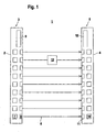
- FIG. 1 shows the structure of a light grid 1 for monitoring a surveillance area.
- the light grid 1 has a transmitter unit 3 integrated in a first housing 2 and a receiver unit 5 integrated in a second housing 4.
- the transmitter unit 3 has an array of transmitting light beams 6 emitting transmitters 7.
- the transmitter 7 preferably consist of identically formed LEDs and are arranged at a distance next to each other lying, the transmitter 7 are preferably arranged equidistantly.
- For beam shaping the transmitted light beams 6 is a transmitter optics 8 upstream of each transmitter 7.
- the transmission optics 8 are arranged in the region of the front wall of the housing 2 behind a not shown separately exit window.
- optical axes of the transmitted light beams 6 guided in the surveillance area run parallel to one another in the plane of the surveillance area.
- the transmitters 7 are controlled by a transmitter control unit 9.
- the transmitter 7 are operated in pulsed mode.
- the individual transmitters 7 cyclically emit transmit light beams 6 one after the other in the form of individual pulses or sequences of pulses, the timing taking place via the transmitter control unit 9.
- the transmitters 7 are sequentially activated within a cycle in accordance with their sequence in the transmitter unit 3 in a predetermined scanning direction.
- the receiver unit 5 has an arrangement of identically formed receivers 10 arranged side by side.
- the receivers 10 preferably each consist of a photodiode and are arranged equidistantly.
- Each receiver 10 is preceded by a receiving optics 11.
- a receiver 10 faces a transmitter 7 of the transmitter unit 3.
- the beam shaping of the transmitted light beams 6 is selected in the present case such that, when the beam path is free, the transmitted light beams 6 of a transmitter 7 only strike the receiver 10 arranged opposite to each other.
- Each transmitter 7 and its associated receiver 10 forms a beam axis of the light grid 1.
- the totality of the beam axes of the light grid 1 defines the monitored area detected with this.
- the receivers 10 are controlled via a receiver control unit 12. Furthermore, the received signals at the output of the receiver 10 are evaluated in the receiver control unit 12. With free beam path of the light grid 1, the transmitted light beams 6 impinge unhindered on the associated Receiver 10 and generate a free beam path corresponding reference received signals. In particular, the evaluation of the received signals in the receiver control unit 12 takes place with a threshold value, the amplitudes of the reference received signals being above the threshold value.
- the beam path of the transmitted light beams 6 of at least one transmitter 7 is interrupted.
- the object consists of a body part 13 of a person.
- the received signal of the assigned receiver 10 is then below the threshold value, that is, at this receiver 10 no reference received signals are registered.
- the interruptions of the beam axes are evaluated in the receiver control unit 12 for generating an object detection signal.
- the object detection signal is designed as a binary switching signal having the switching distances "0" and "1".
- the switching state "0" corresponds to a free beam path of the light grid 1, that is, no object was registered in the control unit.
- the switching state "1" corresponds to an object intervention in the beam path of the light grid 1.
- the interruption of a beam axis is sufficient, so that an object engagement is given.
- the light grid 1 thus forms a personal protection device that prevents persons during the operation of the machine in the apron.
- the term light grids also includes light curtains in which a large number of transmitters and receivers are provided.
- the light grid 1 has a fail-safe construction.
- the receiver control unit 12 has a redundant structure, in particular in the form of two mutually cyclically monitoring computer units.
- the transmitter control unit 9 has a fail-safe construction, whereby a correspondingly secure control of the transmitter 7 of the light grid 1 is ensured.
- such objects can be formed by machine parts or by moving objects, in particular workpieces to be machined on the machine, which do not endanger persons. Upon entry of such objects, stopping the machine via the object detection signal would be unnecessary.
- blanking areas are defined as subregions of the surveillance area within which an object intervention does not lead to the generation of an object detection signal and thus to a shutdown of the machine.
- the blanking areas should be selected so that they correspond exactly to the subregions of the surveillance area within which these objects are located.
- the beam axes lying in the respective blanking area are masked out in the evaluation unit, so that beam interruptions of these beam axes do not lead to the generation of an object detection signal.
- an object detection signal is advantageously generated even if the subject object does not completely cover the blanking area.
- FIG. 2 shows the light grid 1 with a lying in the monitoring area stationary pillar 14 as a non-safety-critical object, which defines a blanking area, which in the present case comprises the first three beam axes of the light grid 1.
- the activation of the transmitter 7 must be synchronized with the activation of the receiver 10, so that each of the transmitter 7 and receiver 10 a beam axis are activated simultaneously.
- a synchronization algorithm is implemented in the receiver control unit 12.
- the synchronization algorithm is formed by software modules by means of which the light grid 1 is programmed.
- the implementation of the synchronization algorithm in the redundantly constructed receiver control unit 12 ensures fail-safe synchronization of the light grid 1.
- a beam axis is generally used, which can be clearly distinguished from the other beam axes by means of the pulse-shaped transmitted light beams 6 emitted by the transmitter 7 of this beam axis. If the pulse-shaped transmitted light beams 6 of the associated transmitter 7 are detected on the associated receiver 10 of this beam axis used for synchronization, the transmitters 7 and receivers 10 of the further beam axes are activated one after the other for operation of the light grid 1 starting from this beam axis. The evaluation of whether the transmit light beams 6 of the associated transmitter 7 are received at a receiver 10 be performed in the receiver control unit 12 such that there are stored corresponding setpoints, which are compared with the currently registered at the respective receiver 10 received signals.
- FIG. 3 shows a first embodiment of the of the transmitters 7 of the light grid 1 according to FIG. 1 emitted pulsed transmitted light rays 6.
- the pulse-shaped transmitted light beams 6 emitted by the transmitter 7 used for synchronization are each shown with I.
- II the emitted by the transmitters 7 all other beam axes pulsed transmitted light beams are shown. This means that all transmitters 7, with the exception of the transmitter 7 used for synchronization, emit pulse-shaped transmitted light beams 7 in an identical manner.
- the transmitter 7 used for synchronization emits transmitted light beams 6 in the form of two pulse groups, the first pulse group comprising two individual pulses and the second pulse group comprising three individual pulses. All pulses have the same pulse width, ie the same duration.
- the pulses of the first pulse group are separated by a pause P I or by a distance A I.
- the term pause generally means the time difference between the last pulse of the first pulse group and the first pulse of the following pulse group.
- the term distance generally means the time difference between the respective first pulse of the first and the following pulse group.
- Pulse groups in the sense of all embodiments are sequences of single pulses, with their time intervals are considerably smaller than the time interval to the next pulse group.
- the pulse width of the pulses and the time intervals between the individual pulses of a pulse group are identical to the corresponding magnitudes for the transmitter 7 used for the synchronization.
- the beam axis used for the synchronization can be unambiguously recognized in the receiver control unit 12.
- the different encodings of the pulse-shaped transmitted light beams 6 can be easily realized via the transmitter control unit 9, since all transmitters emit 7 pulses with identical pulse widths, to distinguish the transmitted light beams 6 different transmitter 7 only the distance or the pause between the pulse groups must be chosen differently , Furthermore, it is advantageous that the pulse groups formed by the pulses form individually coded transmitted light beams 6, which can be easily distinguished in the receiver control unit 12 from incident stray light.
- FIG. 4 shows a further embodiment of the emitted from the transmitters 7 of the light grid 1 pulse-shaped transmitted light beams 6.
- emit each transmitter 7 each have a pulse group consisting of two individual pulses, all pulses have the same pulse width.
- the pulse-shaped transmitted light beams 6 of the transmitter 7 used for synchronization differ in the distance A I or in the pause P I between the pulses from the distance A II or the pause P II of the pulse-shaped Transmitted light beams 6 of the transmitter 7 of all other beam axes. Since each transmitter 7 emits only two individual pulses, a short cycle time of the light grid 1 is obtained. In addition, the pulse groups consisting of two pulses can be easily generated in the transmitter control unit 9.
- FIG. 5 shows an extension of the embodiment according to FIG. 4 ,
- emit all transmitter 7 of the light grid 1 a pulse group consisting of three pulses, the pulse widths of all pulses are identical again.
- the distances A 1I , A 2I or pauses P 1I , P 2I of the pulses of the pulse groups differ from the distances A 1II , A 2II and the pauses P 1II , P 2II, respectively Pulse groups of the transmitted light beams 6 of all other transmitter 7.
- the total transmission time that is, the distance of each first to the last pulse of a pulse group is the same for all transmitters 7.
- FIG. 6 shows a further embodiment of the of the transmitters 7 of the light grid 1 according to FIG. 1 emitted pulsed transmitted light rays 6.
- emit all transmitters 7 each have a pulse group consisting of three individual pulses. The distances or pauses between the pulses of the pulse groups for all transmitters 7 are identical.
- the pulse groups emitted by the transmitters 7 also preclude mutual interference between two closely adjacent light grids 1, which can occur when transmitted light beams 6 strike from transmitters 7 of a light grating 1 to receivers 10 of a second light grating 1.
- FIG. 7 illustrates such a situation of two light grids 1, the transmitter 7, according to the embodiment according to FIG. 4 , each emitting a pulse group consisting of two individual pulses.
- the upper timing diagram shows the pulses of the transmitter 7 of the first light grid 1.
- the lower timing diagram shows the pulses of the transmitter 7 of the second light grid 1.
- FIG. 8 shows a further embodiment of the transmission operation of the light grid 1 according to FIG. 1 ,
- all transmitters 7 emit only one pulse.
- the pulse of the transmitter 7 used for synchronization differs with respect to its pulse width B I from the pulse widths B II of the transmitters 7 of all other beam axes. Because the transmitters 7 emit only individual pulses, a short cycle time of the light grid 1 is obtained. In addition, such individual pulses can be generated with a small amount of hardware.
- the same beam axis is always used to synchronize the light grid 1, the pulse-shaped transmitted light beams 6 of this beam axis differing from the pulse-shaped transmitted light beams 6 of all other beam axes.
- this may be the case in the FIGS. 1 and 2 shown light grids 1 be the topmost beam axis.
- the beam axis for synchronization can be specified time-dependent via the transmitter control unit 9. This can be done take place that the individual pulses or pulse groups, by means of which the synchronization is carried out, are not always impressed on the transmitted light beams 6 of the same transmitter 7. Rather, the transmitter 7 are controlled by the transmitter control unit 9 so that in the areas I of the FIGS. 3 to 8 represented, used for synchronization pulses or pulse groups are emitted in predetermined time clocks of different transmitters 7. Then, with arbitrarily blanked partial areas of the light grid 1, a transmitter 7 of a beam axis which is not hidden will emit the pulses or pulse groups used for synchronization at one time. Since the beam axis is not hidden, the receiver 10 receives the pulses or the pulse groups and the synchronization of the light grid 1 can be performed. In the subsequent operation, the individual transmitters 7 can then emit fixed, constant pulses or pulse groups.
- An alternative solution to the mentioned problem of synchronizing the light grid 1 with existing hidden areas is that not only one transmitter 7 but several transmitters 7 emit individual pulses or pulse groups which are different from the pulses or pulse groups of all other transmitters 7. Then not only one, but it can be used to synchronize the light grid 1 more beam axes. In this case, the synchronization of the light grid 1 takes place in such a way that the beam axes of the light grid 1 are activated one after the other and then the first free beam axis whose transmitter 7 emits pulses or pulse groups with a unique identifier, which are then received by the associated receiver, is used for synchronization becomes.
- the transmitter 7 multiple beam axes in which the transmitter 7 multiple beam axes can be used for synchronization, may be required as a synchronization condition that not only the one unique identifier forming pulses or pulse groups of the transmitter 7 a beam axis from the associated receiver 10 must be received. Rather, the Synchronization condition to be expanded so that for at least two beam axes emitted by the transmitter 7 pulses or pulse groups are received by the associated receiver 10.
- This variant has the advantage that only identifier pairs are formed by the identifiers of the pulses or pulse groups of these transmitters 7 used for synchronization, as a result of which the identifier supply, that is to say the number of available different identifiers, can be increased.
Landscapes
- Physics & Mathematics (AREA)
- Life Sciences & Earth Sciences (AREA)
- General Life Sciences & Earth Sciences (AREA)
- General Physics & Mathematics (AREA)
- Geophysics (AREA)
- Optical Radar Systems And Details Thereof (AREA)
- Optical Communication System (AREA)
- Burglar Alarm Systems (AREA)
Applications Claiming Priority (1)
| Application Number | Priority Date | Filing Date | Title |
|---|---|---|---|
| DE102007059565A DE102007059565B4 (de) | 2007-12-11 | 2007-12-11 | Lichtgitter und Verfahren zu dessen Betrieb |
Publications (3)
| Publication Number | Publication Date |
|---|---|
| EP2071363A2 true EP2071363A2 (fr) | 2009-06-17 |
| EP2071363A3 EP2071363A3 (fr) | 2017-05-24 |
| EP2071363B1 EP2071363B1 (fr) | 2021-07-21 |
Family
ID=40481823
Family Applications (1)
| Application Number | Title | Priority Date | Filing Date |
|---|---|---|---|
| EP08017078.0A Active EP2071363B1 (fr) | 2007-12-11 | 2008-09-27 | Barrière lumineuse et son procédé de fonctionnement |
Country Status (2)
| Country | Link |
|---|---|
| EP (1) | EP2071363B1 (fr) |
| DE (1) | DE102007059565B4 (fr) |
Cited By (10)
| Publication number | Priority date | Publication date | Assignee | Title |
|---|---|---|---|---|
| EP2431768A1 (fr) * | 2010-09-21 | 2012-03-21 | Sick Ag | Barrière lumineuse |
| CN102445713A (zh) * | 2010-10-12 | 2012-05-09 | 西克股份公司 | 光电传感器 |
| EP2813868A1 (fr) * | 2013-06-11 | 2014-12-17 | Cedes Safety & Automation AG | Procédé de synchronisation d'unités optiques d'une barrière photoélectrique et rideau de lumière |
| CN105579869A (zh) * | 2013-06-28 | 2016-05-11 | 皮尔兹外国控股有限责任公司 | 用于同步光栅的方法 |
| CH714428A1 (de) * | 2017-12-14 | 2019-06-14 | Elesta Gmbh Ostfildern De Zweigniederlassung Bad Ragaz | Verfahren zum Betreiben einer Lichtschrankenanordnung und Lichtschrankenanordnung. |
| EP3614182A1 (fr) | 2018-08-22 | 2020-02-26 | Leuze electronic GmbH + Co. KG | Système de barrière lumineuse |
| CN111981306A (zh) * | 2019-05-23 | 2020-11-24 | 上海信索传感器有限公司 | 一种光栅及防干扰的方法 |
| DE202020100872U1 (de) * | 2020-02-18 | 2021-05-25 | Leuze Electronic Gmbh + Co. Kg | Lichtschrankenanordnung |
| EP4485013A1 (fr) | 2023-06-28 | 2025-01-01 | Leuze electronic GmbH + Co. KG | Ensemble barrière lumineuse |
| CN120380381A (zh) * | 2022-07-14 | 2025-07-25 | 塞德斯股份公司 | 具有距离测量的光栅 |
Families Citing this family (3)
| Publication number | Priority date | Publication date | Assignee | Title |
|---|---|---|---|---|
| DE202009007018U1 (de) * | 2009-05-15 | 2010-09-30 | Sick Ag | Optoelektronische Sensoranordnung |
| AT514678A1 (de) * | 2013-05-10 | 2015-02-15 | Thomas Dipl Ing Jerman | Verfahren und Vorrichtung zur Überwachung einer Fläche |
| CN110992585A (zh) * | 2019-12-02 | 2020-04-10 | 合肥美的智能科技有限公司 | 货柜落货检测方法和系统、以及货柜 |
Citations (2)
| Publication number | Priority date | Publication date | Assignee | Title |
|---|---|---|---|---|
| DE3939191A1 (de) | 1989-11-27 | 1991-05-29 | Lumiflex Gmbh & Co Kg Elektron | Mehrstrahlige einweglichtschranke |
| DE102005056000A1 (de) | 2005-11-24 | 2007-05-31 | Sick Ag | Lichtgitter |
Family Cites Families (13)
| Publication number | Priority date | Publication date | Assignee | Title |
|---|---|---|---|---|
| US4063085A (en) * | 1975-11-03 | 1977-12-13 | Cometa S. A. | Method of and apparatus for electronic scanning |
| DE3119876A1 (de) * | 1981-05-19 | 1982-12-16 | Wilhelm Ruf KG, 8000 München | "infrarot-sende-empfangssystem" |
| DE3803033A1 (de) * | 1988-02-02 | 1989-08-10 | Sick Erwin Gmbh | Lichtschrankengitter |
| DE4141468C2 (de) * | 1991-12-16 | 1994-06-30 | Sick Optik Elektronik Erwin | Optische Sensoranordnung und Verfahren zu deren Betrieb |
| DE4224784C2 (de) * | 1992-07-27 | 1995-09-07 | Lumiflex Elektronik Gmbh & Co | Verfahren zum Betrieb von Lichtschranken, Lichtgittern oder Lichtvorhängen |
| DE19510304C1 (de) * | 1995-03-22 | 1996-02-01 | Leuze Electronic Gmbh & Co | Lichtschrankengitter |
| DE19611195C1 (de) * | 1996-03-21 | 1997-06-05 | Lumiflex Elektronik Gmbh & Co | Verfahren zum Betrieb einer Lichtschrankenanordnung |
| DE19925553C2 (de) * | 1999-06-04 | 2003-10-16 | Leuze Lumiflex Gmbh & Co Kg | Optoelektrische Vorrichtung |
| DE10002319A1 (de) * | 2000-01-20 | 2001-07-26 | Sick Ag | Optoelektronische Sensoranordnung und Verfahren zum Betreiben einer optoelektronischen Sensoranordnung |
| DE10033077A1 (de) * | 2000-07-07 | 2002-01-17 | Sick Ag | Lichtgitter |
| DE10202305B4 (de) * | 2001-01-24 | 2004-07-08 | Leuze Electronic Gmbh + Co Kg | Optischer Sensor |
| DE102005047776B4 (de) * | 2005-10-05 | 2007-10-31 | Leuze Lumiflex Gmbh + Co. Kg | Verfahren zum Betrieb eines Lichtgitters |
| DE102006059322B4 (de) * | 2006-12-15 | 2009-03-26 | Leuze Lumiflex Gmbh + Co. Kg | Verfahren zur Erfassung von Objekten in einem Überwachungsbereich mittels eines Lichtgitters |
-
2007
- 2007-12-11 DE DE102007059565A patent/DE102007059565B4/de not_active Revoked
-
2008
- 2008-09-27 EP EP08017078.0A patent/EP2071363B1/fr active Active
Patent Citations (2)
| Publication number | Priority date | Publication date | Assignee | Title |
|---|---|---|---|---|
| DE3939191A1 (de) | 1989-11-27 | 1991-05-29 | Lumiflex Gmbh & Co Kg Elektron | Mehrstrahlige einweglichtschranke |
| DE102005056000A1 (de) | 2005-11-24 | 2007-05-31 | Sick Ag | Lichtgitter |
Cited By (19)
| Publication number | Priority date | Publication date | Assignee | Title |
|---|---|---|---|---|
| EP2431768A1 (fr) * | 2010-09-21 | 2012-03-21 | Sick Ag | Barrière lumineuse |
| US9128201B2 (en) | 2010-09-21 | 2015-09-08 | Sick Ag | Light grid |
| CN102445713B (zh) * | 2010-10-12 | 2016-01-20 | 西克股份公司 | 光电传感器 |
| CN102445713A (zh) * | 2010-10-12 | 2012-05-09 | 西克股份公司 | 光电传感器 |
| EP2461188A3 (fr) * | 2010-10-12 | 2012-06-27 | Sick Ag | Capteur optoélectronique |
| US8836957B2 (en) | 2010-10-12 | 2014-09-16 | Sick Ag | Optoelectronic sensor |
| US9798040B2 (en) | 2013-06-11 | 2017-10-24 | Rockwell Automation Safety Ag | Method for synchronizing optical units of a photoelectric barrier and light curtain |
| EP2813868A1 (fr) * | 2013-06-11 | 2014-12-17 | Cedes Safety & Automation AG | Procédé de synchronisation d'unités optiques d'une barrière photoélectrique et rideau de lumière |
| CN105579869A (zh) * | 2013-06-28 | 2016-05-11 | 皮尔兹外国控股有限责任公司 | 用于同步光栅的方法 |
| US9977148B2 (en) | 2013-06-28 | 2018-05-22 | Pilz Auslandsbeteiligungen Gmbh | Method for synchronizing a light grid |
| CN105579869B (zh) * | 2013-06-28 | 2018-06-19 | 皮尔兹外国控股有限责任公司 | 用于同步光栅的方法 |
| CH714428A1 (de) * | 2017-12-14 | 2019-06-14 | Elesta Gmbh Ostfildern De Zweigniederlassung Bad Ragaz | Verfahren zum Betreiben einer Lichtschrankenanordnung und Lichtschrankenanordnung. |
| EP3499275A1 (fr) * | 2017-12-14 | 2019-06-19 | ELESTA GmbH | Procédé de fonctionnement d'un dispositif de barrière photoélectrique |
| EP3614182A1 (fr) | 2018-08-22 | 2020-02-26 | Leuze electronic GmbH + Co. KG | Système de barrière lumineuse |
| CN111981306A (zh) * | 2019-05-23 | 2020-11-24 | 上海信索传感器有限公司 | 一种光栅及防干扰的方法 |
| DE202020100872U1 (de) * | 2020-02-18 | 2021-05-25 | Leuze Electronic Gmbh + Co. Kg | Lichtschrankenanordnung |
| EP3869241A1 (fr) | 2020-02-18 | 2021-08-25 | Leuze electronic GmbH + Co. KG | Agencement de barrières lumineuses |
| CN120380381A (zh) * | 2022-07-14 | 2025-07-25 | 塞德斯股份公司 | 具有距离测量的光栅 |
| EP4485013A1 (fr) | 2023-06-28 | 2025-01-01 | Leuze electronic GmbH + Co. KG | Ensemble barrière lumineuse |
Also Published As
| Publication number | Publication date |
|---|---|
| DE102007059565B4 (de) | 2010-01-07 |
| DE102007059565A1 (de) | 2009-06-18 |
| EP2071363B1 (fr) | 2021-07-21 |
| EP2071363A3 (fr) | 2017-05-24 |
Similar Documents
| Publication | Publication Date | Title |
|---|---|---|
| EP2071363B1 (fr) | Barrière lumineuse et son procédé de fonctionnement | |
| EP2147338B1 (fr) | Détecteur optoélectronique permettant de sécuriser une zone dangereuse | |
| EP1835310A2 (fr) | Barrière lumineuse | |
| DE102012101369B4 (de) | Lichtvorhang | |
| EP1933174A2 (fr) | Barrière lumineuse | |
| EP2103962A1 (fr) | Capteur optoélectronique | |
| EP3014313B1 (fr) | Procédé de synchronisation d'une barrière lumineuse | |
| DE102007031430B4 (de) | Verfahren zum Betrieb eines Lichtgitters und Lichtgitter | |
| EP1933173B1 (fr) | Barrière lumineuse | |
| DE102018117878A1 (de) | Sicherheitslichtgitter | |
| EP3244237B1 (fr) | Capteur optique et procédé d'opération d'un capteur optique | |
| EP1391752B1 (fr) | Grille de lumière | |
| EP3594553A1 (fr) | Dispositif de surveillance d'une zone de danger | |
| DE10350927A1 (de) | Lichtgitter | |
| EP1772753B1 (fr) | Procédé d'utilisation d'un rideau lumineux | |
| EP2463687B1 (fr) | Capteur optoélectronique | |
| DE102008022791C5 (de) | Lichtvorhang | |
| EP4092449B1 (fr) | Agencement de barrière lumineuse et procédé de détection des objets dans une zone de surveillance | |
| EP2259093B1 (fr) | Dispositif de capteur optoélectronique et procédé de fonctionnement d'un tel dispositif | |
| DE202018104258U1 (de) | Sicherheitslichtgitter | |
| EP3869241B1 (fr) | Agencement de barrières lumineuses | |
| EP1790999B1 (fr) | Barrière lumineuse | |
| EP3168655A1 (fr) | Barrières lumineuses et procédé de détection d'objets | |
| DE20216230U1 (de) | Lichtgitter | |
| EP2251714B1 (fr) | Dispositif de capteur optoélectronique |
Legal Events
| Date | Code | Title | Description |
|---|---|---|---|
| PUAI | Public reference made under article 153(3) epc to a published international application that has entered the european phase |
Free format text: ORIGINAL CODE: 0009012 |
|
| AK | Designated contracting states |
Kind code of ref document: A2 Designated state(s): AT BE BG CH CY CZ DE DK EE ES FI FR GB GR HR HU IE IS IT LI LT LU LV MC MT NL NO PL PT RO SE SI SK TR |
|
| AX | Request for extension of the european patent |
Extension state: AL BA MK RS |
|
| 17P | Request for examination filed |
Effective date: 20140722 |
|
| RBV | Designated contracting states (corrected) |
Designated state(s): AT BE BG CH CY CZ DE DK EE ES FI FR GB GR HR HU IE IS IT LI LT LU LV MC MT NL NO PL PT RO SE SI SK TR |
|
| RAP1 | Party data changed (applicant data changed or rights of an application transferred) |
Owner name: LEUZE ELECTRONIC GMBH + CO. KG |
|
| PUAL | Search report despatched |
Free format text: ORIGINAL CODE: 0009013 |
|
| AK | Designated contracting states |
Kind code of ref document: A3 Designated state(s): AT BE BG CH CY CZ DE DK EE ES FI FR GB GR HR HU IE IS IT LI LT LU LV MC MT NL NO PL PT RO SE SI SK TR |
|
| AX | Request for extension of the european patent |
Extension state: AL BA MK RS |
|
| RIC1 | Information provided on ipc code assigned before grant |
Ipc: G01V 8/20 20060101AFI20170419BHEP |
|
| AKX | Designation fees paid |
Designated state(s): AT BE BG CH CY CZ DE DK EE ES FI FR GB GR HR HU IE IS IT LI LT LU LV MC MT NL NO PL PT RO SE SI SK TR |
|
| AXX | Extension fees paid |
Extension state: BA Extension state: RS Extension state: MK Extension state: AL |
|
| STAA | Information on the status of an ep patent application or granted ep patent |
Free format text: STATUS: EXAMINATION IS IN PROGRESS |
|
| 17Q | First examination report despatched |
Effective date: 20200402 |
|
| GRAP | Despatch of communication of intention to grant a patent |
Free format text: ORIGINAL CODE: EPIDOSNIGR1 |
|
| STAA | Information on the status of an ep patent application or granted ep patent |
Free format text: STATUS: GRANT OF PATENT IS INTENDED |
|
| GRAS | Grant fee paid |
Free format text: ORIGINAL CODE: EPIDOSNIGR3 |
|
| GRAA | (expected) grant |
Free format text: ORIGINAL CODE: 0009210 |
|
| STAA | Information on the status of an ep patent application or granted ep patent |
Free format text: STATUS: THE PATENT HAS BEEN GRANTED |
|
| INTG | Intention to grant announced |
Effective date: 20210526 |
|
| AK | Designated contracting states |
Kind code of ref document: B1 Designated state(s): AT BE BG CH CY CZ DE DK EE ES FI FR GB GR HR HU IE IS IT LI LT LU LV MC MT NL NO PL PT RO SE SI SK TR |
|
| REG | Reference to a national code |
Ref country code: GB Ref legal event code: FG4D Free format text: NOT ENGLISH |
|
| REG | Reference to a national code |
Ref country code: CH Ref legal event code: EP |
|
| REG | Reference to a national code |
Ref country code: DE Ref legal event code: R096 Ref document number: 502008017217 Country of ref document: DE |
|
| REG | Reference to a national code |
Ref country code: AT Ref legal event code: REF Ref document number: 1413090 Country of ref document: AT Kind code of ref document: T Effective date: 20210815 |
|
| REG | Reference to a national code |
Ref country code: IE Ref legal event code: FG4D Free format text: LANGUAGE OF EP DOCUMENT: GERMAN |
|
| REG | Reference to a national code |
Ref country code: LT Ref legal event code: MG9D |
|
| REG | Reference to a national code |
Ref country code: NL Ref legal event code: MP Effective date: 20210721 |
|
| PG25 | Lapsed in a contracting state [announced via postgrant information from national office to epo] |
Ref country code: SE Free format text: LAPSE BECAUSE OF FAILURE TO SUBMIT A TRANSLATION OF THE DESCRIPTION OR TO PAY THE FEE WITHIN THE PRESCRIBED TIME-LIMIT Effective date: 20210721 Ref country code: HR Free format text: LAPSE BECAUSE OF FAILURE TO SUBMIT A TRANSLATION OF THE DESCRIPTION OR TO PAY THE FEE WITHIN THE PRESCRIBED TIME-LIMIT Effective date: 20210721 Ref country code: NL Free format text: LAPSE BECAUSE OF FAILURE TO SUBMIT A TRANSLATION OF THE DESCRIPTION OR TO PAY THE FEE WITHIN THE PRESCRIBED TIME-LIMIT Effective date: 20210721 Ref country code: NO Free format text: LAPSE BECAUSE OF FAILURE TO SUBMIT A TRANSLATION OF THE DESCRIPTION OR TO PAY THE FEE WITHIN THE PRESCRIBED TIME-LIMIT Effective date: 20211021 Ref country code: PT Free format text: LAPSE BECAUSE OF FAILURE TO SUBMIT A TRANSLATION OF THE DESCRIPTION OR TO PAY THE FEE WITHIN THE PRESCRIBED TIME-LIMIT Effective date: 20211122 Ref country code: ES Free format text: LAPSE BECAUSE OF FAILURE TO SUBMIT A TRANSLATION OF THE DESCRIPTION OR TO PAY THE FEE WITHIN THE PRESCRIBED TIME-LIMIT Effective date: 20210721 Ref country code: FI Free format text: LAPSE BECAUSE OF FAILURE TO SUBMIT A TRANSLATION OF THE DESCRIPTION OR TO PAY THE FEE WITHIN THE PRESCRIBED TIME-LIMIT Effective date: 20210721 Ref country code: LT Free format text: LAPSE BECAUSE OF FAILURE TO SUBMIT A TRANSLATION OF THE DESCRIPTION OR TO PAY THE FEE WITHIN THE PRESCRIBED TIME-LIMIT Effective date: 20210721 Ref country code: BG Free format text: LAPSE BECAUSE OF FAILURE TO SUBMIT A TRANSLATION OF THE DESCRIPTION OR TO PAY THE FEE WITHIN THE PRESCRIBED TIME-LIMIT Effective date: 20211021 |
|
| PG25 | Lapsed in a contracting state [announced via postgrant information from national office to epo] |
Ref country code: PL Free format text: LAPSE BECAUSE OF FAILURE TO SUBMIT A TRANSLATION OF THE DESCRIPTION OR TO PAY THE FEE WITHIN THE PRESCRIBED TIME-LIMIT Effective date: 20210721 Ref country code: LV Free format text: LAPSE BECAUSE OF FAILURE TO SUBMIT A TRANSLATION OF THE DESCRIPTION OR TO PAY THE FEE WITHIN THE PRESCRIBED TIME-LIMIT Effective date: 20210721 Ref country code: GR Free format text: LAPSE BECAUSE OF FAILURE TO SUBMIT A TRANSLATION OF THE DESCRIPTION OR TO PAY THE FEE WITHIN THE PRESCRIBED TIME-LIMIT Effective date: 20211022 |
|
| REG | Reference to a national code |
Ref country code: DE Ref legal event code: R097 Ref document number: 502008017217 Country of ref document: DE |
|
| PG25 | Lapsed in a contracting state [announced via postgrant information from national office to epo] |
Ref country code: DK Free format text: LAPSE BECAUSE OF FAILURE TO SUBMIT A TRANSLATION OF THE DESCRIPTION OR TO PAY THE FEE WITHIN THE PRESCRIBED TIME-LIMIT Effective date: 20210721 |
|
| REG | Reference to a national code |
Ref country code: CH Ref legal event code: PL |
|
| REG | Reference to a national code |
Ref country code: BE Ref legal event code: MM Effective date: 20210930 |
|
| PLBE | No opposition filed within time limit |
Free format text: ORIGINAL CODE: 0009261 |
|
| STAA | Information on the status of an ep patent application or granted ep patent |
Free format text: STATUS: NO OPPOSITION FILED WITHIN TIME LIMIT |
|
| PG25 | Lapsed in a contracting state [announced via postgrant information from national office to epo] |
Ref country code: SK Free format text: LAPSE BECAUSE OF FAILURE TO SUBMIT A TRANSLATION OF THE DESCRIPTION OR TO PAY THE FEE WITHIN THE PRESCRIBED TIME-LIMIT Effective date: 20210721 Ref country code: RO Free format text: LAPSE BECAUSE OF FAILURE TO SUBMIT A TRANSLATION OF THE DESCRIPTION OR TO PAY THE FEE WITHIN THE PRESCRIBED TIME-LIMIT Effective date: 20210721 Ref country code: MC Free format text: LAPSE BECAUSE OF FAILURE TO SUBMIT A TRANSLATION OF THE DESCRIPTION OR TO PAY THE FEE WITHIN THE PRESCRIBED TIME-LIMIT Effective date: 20210721 Ref country code: EE Free format text: LAPSE BECAUSE OF FAILURE TO SUBMIT A TRANSLATION OF THE DESCRIPTION OR TO PAY THE FEE WITHIN THE PRESCRIBED TIME-LIMIT Effective date: 20210721 Ref country code: CZ Free format text: LAPSE BECAUSE OF FAILURE TO SUBMIT A TRANSLATION OF THE DESCRIPTION OR TO PAY THE FEE WITHIN THE PRESCRIBED TIME-LIMIT Effective date: 20210721 |
|
| 26N | No opposition filed |
Effective date: 20220422 |
|
| GBPC | Gb: european patent ceased through non-payment of renewal fee |
Effective date: 20211021 |
|
| PG25 | Lapsed in a contracting state [announced via postgrant information from national office to epo] |
Ref country code: LU Free format text: LAPSE BECAUSE OF NON-PAYMENT OF DUE FEES Effective date: 20210927 Ref country code: IT Free format text: LAPSE BECAUSE OF FAILURE TO SUBMIT A TRANSLATION OF THE DESCRIPTION OR TO PAY THE FEE WITHIN THE PRESCRIBED TIME-LIMIT Effective date: 20210721 Ref country code: IE Free format text: LAPSE BECAUSE OF NON-PAYMENT OF DUE FEES Effective date: 20210927 Ref country code: GB Free format text: LAPSE BECAUSE OF NON-PAYMENT OF DUE FEES Effective date: 20211021 Ref country code: FR Free format text: LAPSE BECAUSE OF NON-PAYMENT OF DUE FEES Effective date: 20210930 Ref country code: BE Free format text: LAPSE BECAUSE OF NON-PAYMENT OF DUE FEES Effective date: 20210930 |
|
| PG25 | Lapsed in a contracting state [announced via postgrant information from national office to epo] |
Ref country code: LI Free format text: LAPSE BECAUSE OF NON-PAYMENT OF DUE FEES Effective date: 20210930 Ref country code: CH Free format text: LAPSE BECAUSE OF NON-PAYMENT OF DUE FEES Effective date: 20210930 |
|
| REG | Reference to a national code |
Ref country code: AT Ref legal event code: MM01 Ref document number: 1413090 Country of ref document: AT Kind code of ref document: T Effective date: 20210927 |
|
| PG25 | Lapsed in a contracting state [announced via postgrant information from national office to epo] |
Ref country code: AT Free format text: LAPSE BECAUSE OF NON-PAYMENT OF DUE FEES Effective date: 20210927 |
|
| PG25 | Lapsed in a contracting state [announced via postgrant information from national office to epo] |
Ref country code: HU Free format text: LAPSE BECAUSE OF FAILURE TO SUBMIT A TRANSLATION OF THE DESCRIPTION OR TO PAY THE FEE WITHIN THE PRESCRIBED TIME-LIMIT; INVALID AB INITIO Effective date: 20080927 Ref country code: CY Free format text: LAPSE BECAUSE OF FAILURE TO SUBMIT A TRANSLATION OF THE DESCRIPTION OR TO PAY THE FEE WITHIN THE PRESCRIBED TIME-LIMIT Effective date: 20210721 |
|
| PG25 | Lapsed in a contracting state [announced via postgrant information from national office to epo] |
Ref country code: TR Free format text: LAPSE BECAUSE OF FAILURE TO SUBMIT A TRANSLATION OF THE DESCRIPTION OR TO PAY THE FEE WITHIN THE PRESCRIBED TIME-LIMIT Effective date: 20210721 |
|
| PG25 | Lapsed in a contracting state [announced via postgrant information from national office to epo] |
Ref country code: MT Free format text: LAPSE BECAUSE OF FAILURE TO SUBMIT A TRANSLATION OF THE DESCRIPTION OR TO PAY THE FEE WITHIN THE PRESCRIBED TIME-LIMIT Effective date: 20210721 |
|
| PGFP | Annual fee paid to national office [announced via postgrant information from national office to epo] |
Ref country code: DE Payment date: 20250919 Year of fee payment: 18 |