EP2071956B1 - Machine et ligne de traitement de pâte - Google Patents
Machine et ligne de traitement de pâte Download PDFInfo
- Publication number
- EP2071956B1 EP2071956B1 EP20080022022 EP08022022A EP2071956B1 EP 2071956 B1 EP2071956 B1 EP 2071956B1 EP 20080022022 EP20080022022 EP 20080022022 EP 08022022 A EP08022022 A EP 08022022A EP 2071956 B1 EP2071956 B1 EP 2071956B1
- Authority
- EP
- European Patent Office
- Prior art keywords
- machine
- heads
- processing
- dough
- wheels
- Prior art date
- Legal status (The legal status is an assumption and is not a legal conclusion. Google has not performed a legal analysis and makes no representation as to the accuracy of the status listed.)
- Active
Links
Images


Classifications
-
- A—HUMAN NECESSITIES
- A21—BAKING; EDIBLE DOUGHS
- A21C—MACHINES OR EQUIPMENT FOR MAKING OR PROCESSING DOUGHS; HANDLING BAKED ARTICLES MADE FROM DOUGH
- A21C11/00—Other machines for forming the dough into its final shape before cooking or baking
- A21C11/004—Other machines for forming the dough into its final shape before cooking or baking forming the dough into a substantially disc-like shape with or without an outer rim, e.g. for making pie crusts, cake shells or pizza bases
- A21C11/008—Other machines for forming the dough into its final shape before cooking or baking forming the dough into a substantially disc-like shape with or without an outer rim, e.g. for making pie crusts, cake shells or pizza bases by press-rolling
Definitions
- the present invention finds application in food machinery, and particularly relates to a machine for processing dough, particularly for spreading dough into disks, such as pizza bases or the like.
- the invention further relates to a dough processing line comprising such a machine.
- industrial lines for forming dough disks typically comprise one or more processing stations in succession to perform a number of processing steps of dough portions initially having a spherical or hemispherical shape.
- such lines include one or more processing stations for carrying out a spreading step on the previously pressed dough, which is required to cause it to reach the desired diameter and thickness.
- Spreading is performed by one or more heads that are vertically handled to operate on the dough while the latter lies still on a belt conveyor in a preset position.
- prior art spreading machines have a single spreading head which operates on one dough at a time, in a substantially discontinuous manner. Accordingly, the forming lines that incorporate such spreading stations have a very poor throughput, and it is very difficult to coordinate the production rates of the individual stations with the rate of the whole line.
- the spreading machines are capable of simultaneous operation, they are still operatively independent of and not synchronized with each other. Therefore, in order to prevent the input or output products from building up at the loading and unloading areas respectively of each machine, there is the need for intermediate magazines or loading and unloading stations for each of such machines, with an often unacceptable increase of industrial costs.
- each of the spreading machines in use requires its own power supply, thereby involving increased power consumption, and affecting cost effectiveness of the production process.
- the object of the present invention is to overcome the above drawbacks, by providing a dough processing machine that is highly efficient and relatively cost-effective.
- a particular object is to provide a dough processing machine having a plurality of rotating processing head which have synchronized movements and particularly substantially coincident angular velocities, to ensure high uniformity of the processed products.
- Another object of the present invention is to provide a machine that has a very simple construction, allowing for minimized bulk and considerably increased throughput as compared with a prior art machine with as many processing heads.
- Yet another object is to provide a dough processing machine and line, which afford remarkable power savings as compared with prior art processing machines and lines with the same throughput.
- the processing machine of the invention will be able of driving potentially countless processing heads in a wholly synchronized manner.
- the invention provides a line for processing dough, particularly for forming dough disks, as defined in claim 16.
- the processing line will have a much smaller size, a much lower power consumption as compared with a prior art line with as many processing heads, and will be characterized by a much higher throughput.
- the machine of the invention may be advantageously used for forming dough disks, such as pizza bases or the like.
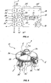
- the machine 1 may be integrated in a common dough processing line, as schematically shown in Fig. 1 and generally designated by numeral 2, which comprises an input 3 for a plurality of dough portions P, P', P'', ..., one or more processing stations 4, 5, 6, 7, 8, an output 9 for the processed dough portions P, P', P'', ..., means 10 for feeding the dough portions P, P', P'', ..., from the input 3 to the output 9, which may include one or more belt conveyors or a roller bed 11, 11', 11'' of known type.
- the line 2 may be particularly suitable for forming dough disks, such as pizza bases or the like, from dough portions P, P', P'', ... initially having a substantially spheroidal shape.
- the line 2 includes a loading station 4 which receives the dough portions P, P', P'', ..., a pressing station 5, a spreading station 6 connected to a downstream calibration station 7 and a finished product unloading station 8.
- the line 2 may also have a configuration other than that described above, with a larger or smaller number of stations, possibly with different alignments according to particular processing requirements.
- the machine 1 of the invention may be located at the spreading station 6 to turn the dough portions P, P', P'', ..., possibly pressed to disks beforehand, into semifinished or finished products with desired thickness and diameter.
- the machine 1 of the invention comprises a bearing frame 12 with a movable or stationary work surface adapted to support a plurality of dough portions P, P', P'', ..., to be processed.
- the work surface 13 may be equipped with a belt conveyor 11 for feeding the dough portions P, P', P'', ....
- the machine 1 further has one or more sets 14 of processing heads 15 located above the work surface 13 and susceptible of interacting with the dough portions P, P', P'', ..., by a rotary movement ⁇ about respective axes X and/or a translational movement t towards/away from the surface.
- numeral 15 only designates one of the processing heads, although all the components mentioned below will be present in a substantially identical manner in all the other processing heads.
- first motor means 16 operatively associated with the processing heads 15
- second motor means 17 are designed to impart the translational movements, schematically designated by the double-pointed arrows t, preferably in a vertical direction W.
- all the processing heads 15 in the set 14 are supported by a plate 18 or the like associated with the frame 12, with the first and second motor means 16, 17 being also connected thereto.
- the plate 18 may be part of a box-like body, not shown, open at its bottom to define a protective shield for all the processing heads 15, but it may be replaced by any other structure acting as a support for the processing heads 15.
- synchronization means 19 are associated with the plate 18 or the like for synchronized transmission of the rotary ⁇ and/or translational t motion from the first and second motor means 16, 17 to all the heads 15 possibly provided in the set 14.
- synchronized rotary ⁇ and/or translational t movements may be imparted to all the heads 15 to cause them to have substantially identical working movements, characterized by substantially coincident angular velocities, excepting the sign, to provide uniform processing of the dough portions P, P', P", ....
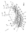
- the synchronization means 19 include a kinematic connection 20 that connects the first motor means 16 to each processing head 15.
- the first motor means 16 include a single motor 21, possibly of known type, which has a drive shaft at its output, possibly with a gearmotor or another kinematic transmission 23 interposed therebetween, and possibly connected, via the kinematic connection 20, to the axis of rotation X of each processing head 15, to impart respective synchronized rotations ⁇ thereto in response to the rotation of the drive shaft only.
- the processing heads 15 may be arranged in a plurality of sets 14, 14', 14", ... of processing heads 15, six in the example of the figures, which are offset in a direction transverse to the longitudinal direction of feed L of the dough portions P, P', P", ... along the machine 1 and/or the line 2.
- Each set 14, 14', 14", ... will in turn be composed of a predetermined number of processing heads 15, four in this example, which are operatively aligned in the longitudinal direction L.
- the number of sets 14, 14', 14", ... may be other than that of the example, i.e. theoretically infinite, their alignment may be also other than a transverse alignment, and the number of heads 15 for each of them may be greater or smaller than four and also theoretically infinite.
- the kinematic connection 20 comprises, for each head 15, a cogwheel or a crown wheel 24, 24', 24'', 24'' integral and coaxial thereto.
- one of the cogwheels or crown wheels 24 may be operatively associated with the drive shaft of the motor 21 via the other components of the kinematic connection 20 to define a first driving wheel, whereas the others will define first driven wheels 24', 24'', 24''' arranged in adjacent positions to act as corresponding first gears.
- first driving and driven wheels 24, 24', 24", 24''' of each set 14 are preferably vertically offset relative to the first driving and driven wheels 24, 24', 24'', 24''' of the adjacent set 14', for further reduction of longitudinal and transverse dimensions.
- the kinematic connection 20 may be designed with the longitudinal sets 14, 14', 14", ... of heads arranged in pairs of substantially similar synchronized sets. Therefore, in the illustrated example, three pairs of longitudinal sets 25, 25', 25" are provided.
- the kinematic connection 20 may include, for each of the pairs 25, 25', 25", so defined, a second driving cog or crown wheel 26, 26', 26" which will receive motion from the drive shaft , and a pair of second driven wheels 27-7, 27'-28', 27"-28” rotatably driven by the same second driving wheel 26, 26', 26" to form respective gears.
- each of the second driven wheels 27, 28; 27', 28'; 27", 28" may have an axis of rotation Y in common with one of the first driving wheels 24, to transmit the rotary motion ⁇ to the latter and hence to all the cogwheel 24', 24", 24"' integral with the heads 15.
- the drive shaft of the motor 21 may have one end connected to a first transmission joint 29 which will have in turn three first driven shafts 30, 30', 30" at its output to transfer motion from the drive shaft to a corresponding second driving wheel 26, 26', 26".
- One or more of the second driving wheels 26, 26', 26" may be connected to the corresponding first driven shaft 30, 30', 30'' via a second transmission joint 31, 31', ... also of known type, which has a second downstream driven shaft 32, 32', ... with the second driving wheels 26, 26'' of the corresponding pair of sets 25, 25', 25'' coaxially mounted thereto.
- the first lateral driven shaft 30, 30'' have a substantially horizontal axis of rotation, whereas the center axis 30' is substantially vertical and directly connected to the first transmission joint 29.
- the second motor means 17 may include one or more actuators 33 connected at one side to the load-bearing frame 12 and at the other to the plate 18, shield or the like, for synchronous translational motion t of the processing heads 15.
- the actuators 33 may be of pneumatic, electromechanical, hydraulic or the like type and may have a substantially vertical axis of actuation W. Their motion may be controlled by a logic control unit, not shown, which is designed to control either the machine 1 only or the whole line 2 as a central unit.
- Fig. 5 shows a possible configuration of the processing heads 15 which may be spreading heads, each having a plurality of cones 34, 34', 34'', ..., three in the illustrated example, rotating about a substantially vertical axis, which may coincide with the axis X of rotation of its own cog or crown wheel 24, 24', 24'', 24'''.
- Each cone 34, 34', 34'', ... may also rotate about an inclined axis Z, Z', Z'', ... to interact with a dough portion P, P', P''....
- the drive shaft which is rotatably supported by the motor 21, will drive into rotation, via the first transmission joint 29, the first two lateral driven shafts 30, 30" and the central driven shaft 30'.
- the former two will transfer their motion to the shafts 32, 32' of the second lateral driving wheels 26, 26" via the second transmission joints 31, 31', whereas the other may be directly connected to the second central driving wheel 26'.
- Each of the second driving wheels 26, 26', 26" will mesh with a pair of second driven wheels 27, 28; 27', 28'; 27", 28" which will in turn rotate a corresponding first driving wheel 24 associated to each set 14.
- Each of the latter wheels will in turn drive into rotation the driven cogwheels 24', 24" adjacent thereto and belonging to the same set 14, which will in turn transfer the rotary motion ⁇ to the adjacent driven cog or crown wheels 24"', thereby causing all the processing heads 15 to be rotated.
- each of the processing heads 14 may have a crown wheel 35 integral with its first driving or driven cogwheel 24, 24', 24", 24"', ... to transmit motion to each cone 34, 34', 34" via a gearing 36, 36', 36" placed at the base of each cone 34, 34', 34".
- synchronization means 19 and particularly the kinematic connection 20 may be easily changed to fit the number of processing heads 15 being used from time to time.
- all the processing heads 15 provided in the machine of the invention will have respective rotary movements and/or translational movements 7 synchronized and substantially similar to each other excepting the direction of rotation, and ensure high uniformity of the output products.
Landscapes
- Life Sciences & Earth Sciences (AREA)
- Engineering & Computer Science (AREA)
- Food Science & Technology (AREA)
- Manufacturing And Processing Devices For Dough (AREA)
Claims (12)
- Une machine de traitement de pâte alimentaire, en particulier pour l'épandage de portions préformés de pâte (P, P ', P", ...) en disques, tels que les bases de pizza ou similaire, comprenant:- un châssis de support (12) avec un plan de travail mobile ou fixe (13) pour supporter une pluralité de portions de pâte (P, P ', P", ...) à traiter;- au moins un ensemble (14) de têtes de traitement (15) situé au-dessus dudit plan de travail (13) et susceptible de coopérer avec lesdites portions de pâte (P, P ', P", ...) par un mouvement de rotation (ω) autour des axes respectifs (X) et/ou par un mouvement de translation (t) vers/à distance de ladite surface (13);- un premier moyen moteur (16) fonctionnellement associé à ladite tête de traitement (15) pour conférer des mouvements de rotation respectifs (ω);- un second moyen moteur (17) fonctionnellement associés à ladite tête (15) pour conférer des mouvements de translation respectifs (t);
dans laquelle toutes les têtes (15) dans ledit au moins un ensemble (14) sont supportés par une plaque (18) ou similaire associée sur ledit châssis (12), un moyen de synchronisation (19) étant prévu qui est associé à ladite plaque (18) ou similaire pour la transmission synchronisée du mouvement à partir dudit premier (16) et dudit second (17) moyen moteur à toutes les têtes (15) dudit ensemble (14), lesdits moyens de synchronisation (19) comprenant une chaîne cinématique (20) qui relie ledit premier moyen moteur (16) à chacune desdites têtes de traitement (15); et an outre
dans laquelle ledit premier moyen moteur (16) présent au moins un arbre d'entraînement à leur sortie, ladite chaîne cinématique (20) étant destiné à connecter fonctionnellement ledit au moins un arbre d'entraînement à chacune desdites têtes de traitement (15) et de communiquer des rotations synchronisées respectifs (ω) à eux mêmes en réponse à la rotation dudit arbre d'entraînement, ladite chaîne cinématique (20) comprenant une roue dentée ou une roue de couronne (24, 24', ', 24", 24"') pour chaque tête (15) dudit ensemble (14), une de ces roues étant associée de manière opérationnelle avec ledit arbre d'entraînement (22) pour définir une première roue d'entraînement, les autres définissant premières roues dentées ou roues couronne entraînées fonctionnellement associées aux roues dentées des têtes de traitement adjacentes (15) dans ledit ensemble (14) pour agir en tant que roues dentées correspondantes. - Machine selon la revendication 1, caractérisé en ce que les têtes (15) dudit ensemble (14) sont fonctionnellement alignés dans une direction sensiblement horizontale longitudinale (L).
- Machine selon la revendication 2, caractérisé en ce qu'elle comprend une paire (25) desdits ensembles longitudinaux (14) des têtes de traitement (15), les ensembles de ladite paire (25) étant décalés le long d'une direction sensiblement horizontale transversale (T).
- Machine selon la revendication 3, caractérisé en ce que ladite chaîne cinématique (20) comprend une deuxième roue dentée ou couronne dentée (26) associée de manière opérationnelle audit arbre d'entraînement (22) et une paire de roue dentée entraînée ou seconde couronnes dentées (27, 28) couplée à ladite deuxième roue d'entraînement (26) pour agir en tant que deuxième engrenages, et à une première roue d'entraînement correspondante (24, 24') d'une série respective (14) desdites têtes de traitement (15).
- Machine selon la revendication 4, caractérisé en ce que chacune desdites secondes roues motrices (27, 28) est coaxiale avec une première roue motrice correspondante (24) de l'un respectif desdits ensembles (14) de têtes de traitement (15).
- Machine selon l'une ou plusieurs des revendications précédentes, caractérisé en ce qu'il comprend une pluralité desdits ensembles longitudinaux (14) des têtes de traitement (15), qui sont mutuellement décalées le long de ladite direction transversale (T) pour définir une pluralité de paires d'ensembles (25, 25 ', 25", ...) associés de manière opérationnelle.
- Machine selon la revendication 6, caractérisé en ce que chacune desdites paires d'ensembles (25, 25', 25", ...) de têtes de traitement (15) comprend une paire desdites premières roues d'entraînement (24) couplées à une pluralité desdites premières roues entraînées (24', 24", ...), une seconde roue d'entraînement (26, 26', 26", ...) associée de manière opérationnelle avec ledit arbre d'entraînement (22) et une paire de secondes roues entraînées (27, 28, 27', 28', 27", 28"; ...) couplé de manière opérationnelle à l'une desdites secondes roues d'entraînement (26, 26 26", ...).
- Machine selon l'une ou plusieurs des revendications précédentes, caractérisé en ce que ladite chaîne cinématique (20) comprend un premier joint de transmission (29) pour le raccordement de l'arbre d'entraînement (22) à chacune desdites secondes roues d'entraînement (26, 26', 26", ...), ledit premier joint de transmission (29) étant connecté à son entrée à l'arbre d'entraînement (22) dudit premier moyen de moteur (21) et en sortie à une pluralité de premiers arbres de sortie (30 , 30 ', 30", ...) associé de manière opérationnelle avec une seconde roue d'entraînement correspondante (26, 26', 26", ...).
- Machine selon la revendication 8, caractérisé en ce que une ou plusieurs desdites secondes roues d'entraînement (26, 26', 26", ...) est monté sur un second arbre de sortie (32, 32', ...) entraînée par un premier arbre entraîné correspondant (30, 30', ...) par l'intermédiaire d'un second joint de transmission (31, 31', ...).
- Machine selon l'une ou plusieurs des revendications précédentes, caractérisé en ce que ledit second moyen moteur (17) comprend au moins un actionneur (33) relié audit châssis de support (12) et à ladite plaque (18) ou similaire pour obtenir un mouvement de translation synchrone (t) desdites têtes de traitement (15).
- Machine selon l'une ou plusieurs des revendications précédentes, caractérisé en ce que lesdites têtes de traitement (15) sont des têtes d'épandage, chacune ayant une pluralité de cônes (34, 34', 34", ...) tournant autour d'un axe (X) sensiblement vertical, chacun desdits cônes (34, 34 ', 34", ...) étant également en rotation autour d'axes inclinés respectifs (Z, Z', Z", ...) pour interagir avec une portion de la pâte (P, P ', P ", ...).
- Une ligne de traitement de pâte alimentaire, en particulier pour former disques de pâte alimentaire, comme les bases de pizza ou similaires, comprenant:- une entrée (3) pour une pluralité de portions de pâte (P, P ', P", ...) à traiter;- une ou plusieurs stations (4, 5, 6, 7, 8) pour traiter les portions de pâte (P, P ', P", ...), au moins une desdites stations (4, 5, 6, 7 , 8) étant une machine selon l'une ou plusieurs des revendications précédentes;- une sortie (9) pour les portions de pâte traitées (P, P ', P", ...),- un moyen (10) pour amener lesdites portions de pâte (P, P ', P", ...) de ladite entrée (3) à ladite sortie (9).
Applications Claiming Priority (1)
| Application Number | Priority Date | Filing Date | Title |
|---|---|---|---|
| ITVI20070324 ITVI20070324A1 (it) | 2007-12-21 | 2007-12-21 | Macchina e linea per la lavorazione di pasta alimentare. |
Publications (3)
| Publication Number | Publication Date |
|---|---|
| EP2071956A2 EP2071956A2 (fr) | 2009-06-24 |
| EP2071956A3 EP2071956A3 (fr) | 2011-11-16 |
| EP2071956B1 true EP2071956B1 (fr) | 2013-05-29 |
Family
ID=40315986
Family Applications (1)
| Application Number | Title | Priority Date | Filing Date |
|---|---|---|---|
| EP20080022022 Active EP2071956B1 (fr) | 2007-12-21 | 2008-12-18 | Machine et ligne de traitement de pâte |
Country Status (3)
| Country | Link |
|---|---|
| EP (1) | EP2071956B1 (fr) |
| ES (1) | ES2418436T3 (fr) |
| IT (1) | ITVI20070324A1 (fr) |
Families Citing this family (2)
| Publication number | Priority date | Publication date | Assignee | Title |
|---|---|---|---|---|
| ITMO20100351A1 (it) * | 2010-12-13 | 2012-06-14 | Roberto Baraldi | Macchina per la stesura della pasta |
| ITUD20110120A1 (it) * | 2011-07-29 | 2013-01-30 | . | Macchina per preparare in modo automatizzato pasta per pizza, o simili alimenti, e relativo procedimento di preparazione |
Family Cites Families (3)
| Publication number | Priority date | Publication date | Assignee | Title |
|---|---|---|---|---|
| US1790943A (en) * | 1931-02-03 | Metal-wobkiifg machine | ||
| US6398539B1 (en) * | 2000-08-15 | 2002-06-04 | Lawrence Equipment, Inc. | Pizza die with seal |
| BRPI0611330A2 (pt) * | 2005-06-03 | 2010-08-31 | Rheon Automatic Machinery Co., Ltd. | método e aparelho para o rolamento de uma massa alimentìcia e uma masssa alimentìcia em formato de disco fabricada pelo método |
-
2007
- 2007-12-21 IT ITVI20070324 patent/ITVI20070324A1/it unknown
-
2008
- 2008-12-18 ES ES08022022T patent/ES2418436T3/es active Active
- 2008-12-18 EP EP20080022022 patent/EP2071956B1/fr active Active
Also Published As
| Publication number | Publication date |
|---|---|
| EP2071956A2 (fr) | 2009-06-24 |
| EP2071956A3 (fr) | 2011-11-16 |
| ITVI20070324A1 (it) | 2009-06-22 |
| ES2418436T3 (es) | 2013-08-13 |
Similar Documents
| Publication | Publication Date | Title |
|---|---|---|
| CN106903062B (zh) | 一种多方位物流分拣转向装置 | |
| EP2254816B1 (fr) | Unité de transfert de produits | |
| JP6588743B2 (ja) | ロール鍛造機とそのロール鍛造方法 | |
| CN106347923A (zh) | 板材输送装置 | |
| CN105382118A (zh) | 冲压机械的工件输送装置 | |
| EP2071956B1 (fr) | Machine et ligne de traitement de pâte | |
| CN102528644B (zh) | 玻璃板的连续研磨装置及玻璃板的连续研磨方法 | |
| CN101569911B (zh) | 面板输送装置 | |
| CN102112233B (zh) | 辊磨机 | |
| JP6892441B2 (ja) | 品物を移送するための移送システム | |
| CN103662690A (zh) | 方向转换装置及搬送装置 | |
| CN217625536U (zh) | 一种摆轮分拣机 | |
| KR102421548B1 (ko) | 복합 가공 장치 | |
| KR200206286Y1 (ko) | 스프링 제조장치 | |
| EP1047600B1 (fr) | Machine a emballer | |
| EP1780127B1 (fr) | Roue empaqueteuse | |
| CN112264614A (zh) | 一种粉末冶金冲压成型设备 | |
| CN105290306B (zh) | 编制混合链机械手 | |
| JP5348797B2 (ja) | ワーク搬送装置及びプレスシステム | |
| JP3916154B2 (ja) | 生地丸め成形装置 | |
| CN219383756U (zh) | 一种送料机 | |
| EP1719552A3 (fr) | Tête de mélange planétaire dans une machine de pétrissage pour produits d'alimentation | |
| KR20170003779U (ko) | 복합프레스장치 | |
| JPH03264141A (ja) | リングローリングミル | |
| CN106628992A (zh) | 新型直角移载机构 |
Legal Events
| Date | Code | Title | Description |
|---|---|---|---|
| PUAI | Public reference made under article 153(3) epc to a published international application that has entered the european phase |
Free format text: ORIGINAL CODE: 0009012 |
|
| AK | Designated contracting states |
Kind code of ref document: A2 Designated state(s): AT BE BG CH CY CZ DE DK EE ES FI FR GB GR HR HU IE IS IT LI LT LU LV MC MT NL NO PL PT RO SE SI SK TR |
|
| AX | Request for extension of the european patent |
Extension state: AL BA MK RS |
|
| RAP1 | Party data changed (applicant data changed or rights of an application transferred) |
Owner name: ITECA S.P.A. |
|
| PUAL | Search report despatched |
Free format text: ORIGINAL CODE: 0009013 |
|
| AK | Designated contracting states |
Kind code of ref document: A3 Designated state(s): AT BE BG CH CY CZ DE DK EE ES FI FR GB GR HR HU IE IS IT LI LT LU LV MC MT NL NO PL PT RO SE SI SK TR |
|
| AX | Request for extension of the european patent |
Extension state: AL BA MK RS |
|
| RIC1 | Information provided on ipc code assigned before grant |
Ipc: A21C 11/00 20060101AFI20111008BHEP |
|
| 17P | Request for examination filed |
Effective date: 20120327 |
|
| AKX | Designation fees paid |
Designated state(s): DE ES FR GB IT |
|
| 17Q | First examination report despatched |
Effective date: 20120703 |
|
| GRAP | Despatch of communication of intention to grant a patent |
Free format text: ORIGINAL CODE: EPIDOSNIGR1 |
|
| GRAS | Grant fee paid |
Free format text: ORIGINAL CODE: EPIDOSNIGR3 |
|
| GRAA | (expected) grant |
Free format text: ORIGINAL CODE: 0009210 |
|
| AK | Designated contracting states |
Kind code of ref document: B1 Designated state(s): DE ES FR GB IT |
|
| REG | Reference to a national code |
Ref country code: GB Ref legal event code: FG4D |
|
| REG | Reference to a national code |
Ref country code: DE Ref legal event code: R096 Ref document number: 602008024952 Country of ref document: DE Effective date: 20130725 |
|
| REG | Reference to a national code |
Ref country code: ES Ref legal event code: FG2A Ref document number: 2418436 Country of ref document: ES Kind code of ref document: T3 Effective date: 20130813 |
|
| PLBE | No opposition filed within time limit |
Free format text: ORIGINAL CODE: 0009261 |
|
| STAA | Information on the status of an ep patent application or granted ep patent |
Free format text: STATUS: NO OPPOSITION FILED WITHIN TIME LIMIT |
|
| 26N | No opposition filed |
Effective date: 20140303 |
|
| REG | Reference to a national code |
Ref country code: DE Ref legal event code: R097 Ref document number: 602008024952 Country of ref document: DE Effective date: 20140303 |
|
| REG | Reference to a national code |
Ref country code: FR Ref legal event code: PLFP Year of fee payment: 8 |
|
| REG | Reference to a national code |
Ref country code: FR Ref legal event code: PLFP Year of fee payment: 9 |
|
| REG | Reference to a national code |
Ref country code: FR Ref legal event code: PLFP Year of fee payment: 10 |
|
| REG | Reference to a national code |
Ref country code: FR Ref legal event code: PLFP Year of fee payment: 11 |
|
| P01 | Opt-out of the competence of the unified patent court (upc) registered |
Effective date: 20230608 |
|
| PGFP | Annual fee paid to national office [announced via postgrant information from national office to epo] |
Ref country code: DE Payment date: 20251222 Year of fee payment: 18 |
|
| PGFP | Annual fee paid to national office [announced via postgrant information from national office to epo] |
Ref country code: GB Payment date: 20251218 Year of fee payment: 18 |
|
| PGFP | Annual fee paid to national office [announced via postgrant information from national office to epo] |
Ref country code: IT Payment date: 20251219 Year of fee payment: 18 |
|
| PGFP | Annual fee paid to national office [announced via postgrant information from national office to epo] |
Ref country code: FR Payment date: 20251218 Year of fee payment: 18 |
|
| PGFP | Annual fee paid to national office [announced via postgrant information from national office to epo] |
Ref country code: ES Payment date: 20260123 Year of fee payment: 18 |