EP2072103B1 - Filterpatrone und Ölfilter eines Verbrennungsmotors - Google Patents
Filterpatrone und Ölfilter eines Verbrennungsmotors Download PDFInfo
- Publication number
- EP2072103B1 EP2072103B1 EP08165912A EP08165912A EP2072103B1 EP 2072103 B1 EP2072103 B1 EP 2072103B1 EP 08165912 A EP08165912 A EP 08165912A EP 08165912 A EP08165912 A EP 08165912A EP 2072103 B1 EP2072103 B1 EP 2072103B1
- Authority
- EP
- European Patent Office
- Prior art keywords
- valve
- filter
- oil filter
- filter cartridge
- oil
- Prior art date
- Legal status (The legal status is an assumption and is not a legal conclusion. Google has not performed a legal analysis and makes no representation as to the accuracy of the status listed.)
- Not-in-force
Links
- 238000002485 combustion reaction Methods 0.000 title claims description 9
- 230000006835 compression Effects 0.000 claims description 10
- 238000007906 compression Methods 0.000 claims description 10
- 239000003921 oil Substances 0.000 description 34
- 238000012423 maintenance Methods 0.000 description 9
- 238000007789 sealing Methods 0.000 description 6
- 238000004519 manufacturing process Methods 0.000 description 3
- 230000002093 peripheral effect Effects 0.000 description 3
- 210000002105 tongue Anatomy 0.000 description 3
- 238000010276 construction Methods 0.000 description 2
- 238000001914 filtration Methods 0.000 description 2
- 230000005484 gravity Effects 0.000 description 2
- 238000004026 adhesive bonding Methods 0.000 description 1
- 125000004122 cyclic group Chemical group 0.000 description 1
- 230000007423 decrease Effects 0.000 description 1
- 238000009434 installation Methods 0.000 description 1
- 239000010687 lubricating oil Substances 0.000 description 1
- 238000005461 lubrication Methods 0.000 description 1
- 230000007257 malfunction Effects 0.000 description 1
- 239000002245 particle Substances 0.000 description 1
- 230000010349 pulsation Effects 0.000 description 1
- 238000003466 welding Methods 0.000 description 1
Images
Classifications
-
- B—PERFORMING OPERATIONS; TRANSPORTING
- B01—PHYSICAL OR CHEMICAL PROCESSES OR APPARATUS IN GENERAL
- B01D—SEPARATION
- B01D35/00—Filtering devices having features not specifically covered by groups B01D24/00 - B01D33/00, or for applications not specifically covered by groups B01D24/00 - B01D33/00; Auxiliary devices for filtration; Filter housing constructions
- B01D35/14—Safety devices specially adapted for filtration; Devices for indicating clogging
- B01D35/147—Bypass or safety valves
-
- B—PERFORMING OPERATIONS; TRANSPORTING
- B01—PHYSICAL OR CHEMICAL PROCESSES OR APPARATUS IN GENERAL
- B01D—SEPARATION
- B01D35/00—Filtering devices having features not specifically covered by groups B01D24/00 - B01D33/00, or for applications not specifically covered by groups B01D24/00 - B01D33/00; Auxiliary devices for filtration; Filter housing constructions
- B01D35/16—Cleaning-out devices, e.g. for removing the cake from the filter casing or for evacuating the last remnants of liquid
-
- B—PERFORMING OPERATIONS; TRANSPORTING
- B01—PHYSICAL OR CHEMICAL PROCESSES OR APPARATUS IN GENERAL
- B01D—SEPARATION
- B01D2201/00—Details relating to filtering apparatus
- B01D2201/29—Filter cartridge constructions
- B01D2201/291—End caps
-
- B—PERFORMING OPERATIONS; TRANSPORTING
- B01—PHYSICAL OR CHEMICAL PROCESSES OR APPARATUS IN GENERAL
- B01D—SEPARATION
- B01D29/00—Filters with filtering elements stationary during filtration, e.g. pressure or suction filters, not covered by groups B01D24/00 - B01D27/00; Filtering elements therefor
- B01D29/11—Filters with filtering elements stationary during filtration, e.g. pressure or suction filters, not covered by groups B01D24/00 - B01D27/00; Filtering elements therefor with bag, cage, hose, tube, sleeve or like filtering elements
- B01D29/13—Supported filter elements
- B01D29/15—Supported filter elements arranged for inward flow filtration
- B01D29/21—Supported filter elements arranged for inward flow filtration with corrugated, folded or wound sheets
Definitions
- the invention relates to a filter cartridge of an internal combustion engine in particular for motor vehicles with the features according to the preamble of claim 1 and an oil filter with the features according to the preamble of claim 8.
- Oil filters of internal combustion engines in the previously known design have a filter housing into which a replaceable filter cartridge is inserted.
- the oil filter is located in an oil circuit through which the lubricating oil is pumped by means of a pump. In normal operation, the oil passes from a raw side through the filter body of the filter cartridge through to the clean side, where it is cleaned by entrained particles.
- the flow resistance of the filter cartridge can be too large, which leads to an undersupply of oil lubrication points without additional measures. This can occur in particular during the cold start of the internal combustion engine, wherein the oil has a very high viscosity due to the low temperature, which leads to an excessively high flow resistance on the filter element.
- a filter bypass valve is provided, which opens automatically above a predetermined differential pressure, the oil through the filter bypass valve passes directly from the raw side to the clean side without flow through the filter body. As the operating temperature of the oil increases, its viscosity decreases, which also reduces the differential pressure at the filter bypass valve. When the temperature falls below a certain viscosity, the filter bypass valve closes again, whereby the filter body is flowed through in the intended manner and thereby absorbs its filtration function.
- the filter bypass valve integrated in the detachable housing part must be elaborately designed and dimensioned as a so-called lifetime component in order to ensure reliable operation throughout the life of the filter. This sets a cautious Handling prior to maintenance. Damage caused by operating errors and subsequent malfunctions can not be safely ruled out.
- the EP-A-1419809 , the WO-A-01/07819 and the FE-A-2885819 disclose both a filter bypass valve and a filter drain valve. The operation of the valves necessarily requires a relative movement between the element on which the valve seat for the filter bypass valve is formed, and the valve body of the drain valve.
- the invention has the object of developing a generic filter cartridge such that increased reliability is achieved.
- the invention is also based on the object of specifying an oil filter which has an increased reliability in a simplified structure.
- the invention relates to a filter cartridge for an oil filter of an internal combustion engine, in particular for motor vehicles, in which the filter cartridge has a filter bypass valve attached to it so that the filter cartridge together with the filter bypass valve forms an assembly intended for joint replacement.
- the filter bypass valve is fixedly connected to the filter cartridge so that the user is forced to replace the filter bypass valve with the filter cartridge during regular maintenance.
- a new filter cartridge ensures that a new filter bypass valve is installed.
- the latter can be easily designed and dimensioned as a replacement part.
- a new filter bypass valve is used, despite the simple and inexpensive design a durable functional and operational safety is achieved.
- the filter bypass valve may be attached to it at any suitable point of the filter cartridge in particular insoluble.
- the filter cartridge has a substantially cylindrically shaped, along a longitudinal axis extending filter body with two opposite end faces, wherein at least one of the end faces an end plate is fixed to the filter body, and wherein the filter bypass valve is arranged on the end plate.
- the end plate is permanently connected to the filter body, whereby a non-detachable connection between the filter bypass valve and the filter cartridge is formed.
- At least part of the filter bypass valve is formed integrally with the end disk.
- the filter bypass valve has a linearly displaceable against a compression spring valve body, wherein the compression spring is supported against a pressure surface of the end plate.
- the valve body is expediently guided on an integrally formed on the end plate linear guide.
- the one-piece design of the linear guide with the end plate ensures reliable operation and positional fixation of the valve body relative to the filter cartridge at low production costs. With a simple structure, a reliable function over the life cycle of regularly exchanged unit is ensured.
- a separate valve housing part is provided with a valve seat for the valve body and in particular latching attached to the end plate.
- the valve housing part with the valve seat can be produced simply, inexpensively and with high precision as a separate component on its own become. A subsequent assembly together with the spring-biased valve body is possible in particular in conjunction with the aforementioned locking with little effort.
- An appropriately designed oil filter is provided with a filter housing having a drain valve for emptying the filter housing during maintenance.
- the valve housing part carrying the valve seat of the filter bypass valve advantageously forms a valve body for the drain valve.
- the valve housing part carrying the valve seat advantageously has an axial play with respect to the filter cartridge and in particular with respect to its end disk.
- the filter housing has a coaxially aligned cylindrical valve seat for the valve body of the drain valve.
- the filter cartridge may expand or contract axially, with the aforesaid axial clearance maintaining a reliable sealing function of the filter bypass valve independent of these dimensional changes.
- the cylindrical sealing seat of the drain valve is insensitive to axial position variations of the valve body. Only when the removable housing part is deducted by a certain axial dimension of the valve body of the drain valve, the oil can drain.
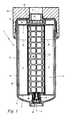
- Fig. 1 shows a longitudinal sectional view of an inventive oil filter 1 of an internal combustion engine, especially for motor vehicles.
- the oil filter 1 comprises a filter housing 17 with a motor-fixed housing upper part 26 and a housing lower part 27 screwed therein.
- an exchangeable filter cartridge 2 for filtering a passing oil flow.
- the lower housing part 27 and the filter cartridge 2 are formed substantially cylindrical, wherein they extend coaxially along a longitudinal axis 4.
- the filter cartridge 2 comprises a substantially cylindrical filter body 5 with two opposite in the axial direction end faces 6, 7. At the two end faces 6, 7 each have an end plate 8, 19 inextricably connected to the filter body 5.
- Radially inside the filter body 5 extends in the direction of the longitudinal axis 4, a grid-like support tube 23 which is held between the two end plates 8, 19, and which is exchanged as part of the filter cartridge 2 together with this.
- a tubular threaded connector 24 is screwed.
- the threaded connector 24 carries on its inside a double hexagon socket, by means of which it can be turned on or unscrewed.
- a circumferential collar 22 is integrally formed.
- the filter cartridge 2 is releasably pushed with this collar 22 sealingly on the freely projecting into the interior of the filter housing 18 peripheral surface of the threaded connector 24.
- the end plate 8 and the end plate 19 separate together with the collar 22 an outer raw side 28 of the filter cartridge 2 from an inner clean side 29 of the filter cartridge 2 and the oil filter 1.
- the oil filter 1 also has a filter bypass valve 3, which opens above a certain pressure difference between the raw side 28 and the clean side 29.
- a filter bypass valve 3 opens above a certain pressure difference between the raw side 28 and the clean side 29.
- Such increased pressure difference over normal operation may occur, for example, during cold start of the internal combustion engine, if the oil viscosity for a normal passage through the filter body 5 corresponding to the arrows 20 is too high.
- the oil flow, bypassing the filter body 5 enters the clean side 29 directly from the dirty side 28 through the filter bypass valve 3.
- the oil filter 1 is shown in its usual hanging mounting position, according to which the upper housing part 26 opposite lower end of the housing base 27 is in gravity below. There, the lower housing part 27 is provided with a drain valve 16, through which oil can be drained from the interior of the filter housing 17 during maintenance work.
- the filter bypass valve 3 and the drain valve 16 are arranged coaxially with the longitudinal axis 4.
- the filter bypass valve 3 and a valve body 15 ( Fig. 2 ) of the drain valve 16 firmly connected to the filter cartridge 2. Together with the filter cartridge 2, including its end disks 8, 19 and the support tube 23, they form a construction and maintenance unit, which is replaced in total at prescribed maintenance intervals.
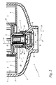
- Fig. 2 shows an enlarged detail view of the arrangement according to Fig. 1 in the region of the filter bypass valve 3 and the drain valve 16.
- the filter bypass valve 3 is arranged on the lower end disk 8 of the filter cartridge 2.
- a part of the filter bypass valve 3 is formed integrally with the end plate 8 as follows: Coaxially to the longitudinal axis 4 protrude in the axial direction of a cylindrical linear guide 12 and an outside at a distance the linear guide 12 enclosing sleeve 39, starting from the end plate 8 and from the clean side 29 out.
- an annular pressure surface 11 for a pressure spring 9 applied thereto is formed by the end plate 8, an annular pressure surface 11 for a pressure spring 9 applied thereto.
- the pressure surface 11, the linear guide 12 and the sleeve 39 are integrally formed with the end plate 8.
- a valve body 10 manufactured as a separate part is pushed onto the linear guide 12 and slidably guided on it in a coaxial manner.
- the compression spring 9 bears against the valve body 10 at its end opposite the pressure surface 11. By a biasing force of the compression spring 9, the valve body 10 is biased from the clean side forward parallel to the longitudinal axis 4.
- valve housing part 13 is provided with a conical valve seat 14 for the valve body 10.
- the valve housing part 13 with the valve seat 14 may be permanently and non-detachably connected to the end plate 8, for example, by welding, gluing or the like. It may also be expedient to mold the valve seat 14 in a section of the end disk 8.
- the valve housing part 13 is latchingly attached to the end plate.
- the sleeve 39 is provided with a circumferentially circumferential locking edge 35.
- the valve housing part 13 has latching tongues 34, which engage behind the latching edge 35 with an axial clearance a. As a result, the valve housing part 13 is held captive on the sleeve 39 of the end plate 8.
- the sleeve 39 is still provided on its peripheral side with a circumferential sealing ring 36 which seals the valve housing 13 on the output side of the valve seat 14 relative to the sleeve 39, but allows in conjunction with the axial play a relative movement of the valve housing part 13 relative to the sleeve 39.
- the valve housing part 13 is still provided on the inlet side of the valve seat 14 with windows 33, according to which the prevailing on the raw side 28 oil pressure on the outer or lower end face of the valve body 10 acts.
- the biasing force of the compression spring 9 is overcome, as a result of which the valve body 10 lifts off from its sealing seat 14 in the direction of an arrow 31 coaxially with the longitudinal axis 4.
- oil can pass directly through the windows 33 past the valve seat 14 in accordance with an arrow 32, bypassing the filter body 5, from the raw side 28 to the clean side 29.
- the housing part 27 is provided at its lower end in the direction of gravity with a arranged coaxially to the longitudinal axis 4 drain opening 37 and with a cylindrical, also arranged coaxially to the longitudinal axis 4 valve seat 18.
- a valve body 15 of the drain valve 16 carries at its lower end on its peripheral wall a circumferential sealing ring 30 which seals the valve body 15 relative to the valve seat 18 of the housing base 27. In this case, however, a relative movement of the valve body 15 is possible axially parallel to the longitudinal axis 4.
- the valve housing part 13 of the filter bypass valve 3 and the valve body 15 of the drain valve 16 are integrally formed, according to which the valve seat part 14 carrying the valve housing part 3 at the same time also forms the valve body 15 for the drain valve 16.
- the filter cartridge 2 due to the axial play a relative to the bottom of the housing base 27 perform an axial relative movement, without the valve body 10 of the filter bypass valve 3 lifts from its valve seat 14, and without the valve body 15 is pulled out of its operating position shown from the valve seat 18 , The tightness of the drain valve 16 and the reliability of the filter bypass valve 3 are permanently ensured.
- the lower housing part 27 is initially only partially removed from the upper housing part 26 (FIG. Fig. 1 ), wherein it performs relative to this an axial relative movement in the direction of the arrow 38. Since the filter cartridge 2 on the threaded connector 24 ( Fig. 1 ), this axial relative movement of the upper housing part 27 also takes place with respect to the filter cartridge 2, the filter bypass valve 3 integrated therein and the valve body 15 of the drainage valve 16. Since the valve body 15 is fixed by means of the latching tongue 34 on the filter cartridge 2, it is pulled out upon further screwing the housing base 27 from the cylindrical sealing seat 18, as a result, located in the interior of the filter housing 17 oil through the drain opening 37 can expire.
Landscapes
- Chemical & Material Sciences (AREA)
- Chemical Kinetics & Catalysis (AREA)
- Lubrication Details And Ventilation Of Internal Combustion Engines (AREA)
- Filtration Of Liquid (AREA)
Description
- Die Erfindung betrifft eine Filterpatrone eines Verbrennungsmotors insbesondere für Kraftfahrzeuge mit den Merkmalen nach dem Oberbegriff des Anspruchs 1 sowie einen Ölfilter mit den Merkmalen nach dem Oberbegriff des Anspruchs 8.
- Ölfilter von Verbrennungsmotoren in vorbekannter Bauform weisen ein Filtergehäuse auf, in das eine auswechselbare Filterpatrone eingesetzt ist. Der Ölfilter befindet sich in einem Ölkreislauf, durch den Schmieröl mittels einer Pumpe hindurchgepumpt wird. Im gewöhnlichen Betrieb tritt dabei das Öl von einer Rohseite durch den Filterkörper der Filterpatrone hindurch zur Reinseite, wobei es von mitgeführten Partikeln gereinigt wird.
- Unter bestimmten Betriebsbedingungen kann der Durchströmungswiderstand der Filterpatrone zu groß werden, was ohne zusätzliche Maßnahmen zu einer Unterversorgung der Schmierstellen mit Öl führt. Dies kann insbesondere beim Kaltstart des Verbrennungsmotors auftreten, wobei das Öl infolge der niedrigen Temperatur eine sehr hohe Viskosität aufweist, die zu einem übermäßig hohen Durchströmungswiderstand am Filterelement führt. Für solche oder vergleichbare Betriebszustände ist ein Filterumgehungsventil vorgesehen, welches oberhalb eines vorgegebenen Differenzdruckes selbsttätig öffnet, wobei das Öl durch das Filterumgehungsventil ohne Durchströmung des Filterkörpers direkt von der Rohseite zur Reinseite gelangt. Mit steigender Betriebstemperatur des Öls sinkt seine Viskosität, womit auch der Differenzdruck am Filterumgehungsventil geringer wird. Beim temperaturbedingten Unterschreiten einer bestimmten Viskosität schließt das Filterumgehungsventil wieder, wodurch der Filterkörper in vorgesehener Weise durchströmt wird und dabei seine Filtrierfunktion aufnimmt.
- Aus der
EP 1 419 809 A1 ist ein derartiger Ölfilter mit einer auswechselbaren Filterpatrone und einem Filterumgehungsventil bekannt. Das Filterumgehungsventil ist in einem abschraubbaren Gehäuseteil des Filtergehäuses angeordnet und wird bei Wartungsarbeiten gemeinsam mit diesem Gehäuseteil abgenommen. Hierbei kann die Filterpatrone ausgewechselt werden. Das abnehmbare Gehäuseteil weist zudem noch ein Ablaufventil auf. Mit diesem Ablaufventil kann der Innenraum des Ölfilters vor der Demontage entleert werden. Nach Auswechseln der Filterpatrone wird die Baueinheit aus dem unteren Gehäuseteil, dem Filterumgehungsventil und dem Ablaufventil wieder eingeschraubt, wonach der Verbrennungsmotor in Betrieb genommen werden kann. - Das in das abnehmbare Gehäuseteil integrierte Filterumgehungsventil muss als sogenanntes Lebensdauerbauteil aufwändig gestaltet und dimensioniert werden, um eine zuverlässige Funktion während der gesamten Lebensdauer des Filters sicherzustellen. Dies setzt eine vorsichtige Handhabung bei Wartungsarbeiten voraus. Beschädigungen durch Fehlbedienungen und in der Folge Fehlfunktionen können nicht sicher ausgeschlossen werden.
DieEP-A-1419809 , dieWO-A-01/07819 FE-A-2885819 - Der Erfindung liegt die Aufgabe zugrunde, eine gattungsgemäße Filterpatrone derart weiterzubilden, dass eine erhöhte Betriebssicherheit erzielt wird.
- Diese Aufgabe wird durch eine Filterpatrone mit den Merkmalen des Anspruchs 1 gelöst.
- Der Erfindung liegt des Weiteren die Aufgabe zugrunde, einen Ölfilter anzugeben, der bei vereinfachtem Aufbau eine erhöhte Betriebssicherheit aufweist.
- Diese Aufgabe wird durch einen Ölfilter mit den Merkmalen des Anspruchs 9 gelöst.
- Es wird eine Filterpatrone für einen Ölfilter eines Verbrennungsmotors insbesondere für Kraftfahrzeuge vorgeschlagen, bei dem die Filterpatrone ein derart an ihr befestigtes Filterumgehungsventil aufweist, dass die Filterpatrone zusammen mit dem Filterumgehungsventil eine zum gemeinsamen Austausch vorgesehene Baueinheit bildet. Das Filterumgehungsventil ist fest mit der Filterpatrone verbunden, so dass der Benutzer gezwungen ist, bei regelmäßigen Wartungsarbeiten das Filterumgehungsventil gemeinsam mit der Filterpatrone auszutauschen. Mit jedem Einsatz einer neuen Filterpatrone ist sichergestellt, dass auch ein neues Filterumgehungsventil eingebaut wird. Letzteres kann als Austauschteil einfach gestaltet und dimensioniert sein. Da mit jedem Austausch der Filterpatrone erzwungenermaßen auch ein neues Filterumgehungsventil eingesetzt wird, ist trotz der einfachen und kostengünstigen Ausgestaltung eine dauerhafte Funktions- und Betriebssicherheit erreicht.
- Das Filterumgehungsventil kann an jeder geeigneten Stelle der Filterpatrone insbesondere unlösbar an ihr befestigt sein. In bevorzugter Weiterbildung weist die Filterpatrone einen im Wesentlichen zylindrisch ausgebildeten, sich entlang einer Längsachse erstreckenden Filterkörper mit zwei gegenüberliegenden Stirnseiten auf, wobei an zumindest einer der Stirnseiten eine Endscheibe am Filterkörper befestigt ist, und wobei das Filterumgehungsventil an der Endscheibe angeordnet ist. Die Endscheibe ist unlösbar mit dem Filterkörper verbunden, wodurch auch eine unlösbare Verbindung zwischen dem Filterumgehungsventil und der Filterpatrone gebildet ist. Es entsteht eine koaxiale Bauweise mit geringem Platzbedarf bei hoher Funktionssicherheit.
- Vorteilhaft ist zumindest ein Teil des Filterumgehungsventils einteilig mit der Endscheibe ausgebildet. Hierdurch werden mehrere Vorteile erreicht: Neben einer kostengünstigen Fertigung als Austauschteil ergibt sich selbst bei schwacher Dimensionierung ein hohes Maß an Strukturfestigkeit und Lagegenauigkeit, was der Betriebssicherheit zugute kommt. Des Weiteren ist der erneute Einsatz eines gebrauchten Filterumgehungsventils zuverlässig verhindert, was ebenfalls zur Steigerung der Betriebssicherheit beiträgt.
- Es kommen verschiedene geeignete Ausführungsformen des Filterumgehungsventils in Betracht. Bevorzugt weist das Filterumgehungsventil einen linear gegen eine Druckfeder verschiebbaren Ventilkörper auf, wobei die Druckfeder gegen eine Druckfläche der Endscheibe abgestützt ist. Bei konstruktiv einfachem Aufbau lässt sich eine zuverlässige Schaltfunktion des Filterumgehungsventils zwischen seinem geöffneten und seinem geschlossenen Zustand bei präzise einstellbarer und reproduzierbarer Schaltdruckdifferenz sicherstellen.
- Der Ventilkörper ist zweckmäßig auf einer an der Endscheibe angeformten Linearführung geführt. Die einteilige Ausgestaltung der Linearführung mit der Endscheibe stellt bei geringen Fertigungskosten eine zuverlässige Führung und Lagefixierung des Ventilkörpers relativ zur Filterpatrone sicher. Bei einfachem Aufbau ist eine zuverlässige Funktion über den Lebenszyklus der regelmäßig auszutauschenden Baueinheit sichergestellt.
- Bevorzugt ist ein separates Ventilgehäuseteil mit einem Ventilsitz für den Ventilkörper vorgesehen und insbesondere rastend an der Endscheibe befestigt. Das Ventilgehäuseteil mit dem Ventilsitz kann einfach, kostengünstig und mit hoher Präzision als separates Bauteil für sich alleine hergestellt werden. Eine anschließende Montage zusammen mit dem federvorgespannten Ventilkörper ist insbesondere im Zusammenspiel mit der vorgenannten Verrastung mit geringem Aufwand möglich.
- Ein entsprechend ausgestalteter Ölfilter ist mit einem Filtergehäuse versehen, welches ein Ablaufventil zum Entleeren des Filtergehäuses bei Wartungsarbeiten aufweist. Das den Ventilsitz des Filterumgehungsventils tragende Ventilgehäuseteil bildet vorteilhaft einen Ventilkörper für das Ablaufventil. Hierdurch wird eine Baueinheit gebildet, bei deren zyklischen Auswechseln neben der Filterpatrone und dem Filterumgehungsventil auch der Ventilkörper des Ablaufventils mit ausgetauscht wird. Bei einfachem Aufbau und Handhabbarkeit kann eine dauerhafte Dichtigkeit des Ablaufventils erreicht werden.
- Das den Ventilsitz tragende Ventilgehäuseteil weist vorteilhaft gegenüber der Filterpatrone und insbesondere gegenüber deren Endscheibe ein Axialspiel auf. Bevorzugt weist das Filtergehäuse einen koaxial dazu ausgerichteten zylindrischen Ventilsitz für den Ventilkörper des Ablaufventils auf. Hierdurch werden Maßschwankungen zwischen der Filterpatrone und dem Filtergehäuse ausgeglichen, die infolge von Fertigungstoleranzen, Druckpulsationen, Temperaturänderungen oder dergleichen auftreten. Die Filterpatrone kann sich in Axialrichtung ausdehnen oder zusammenziehen, wobei das vorgenannte Axialspiel unabhängig von diesen Maßänderungen eine zuverlässige Dichtfunktion des Filterumgehungsventils aufrecht erhält. Auch der zylindrische Dichtsitz des Ablaufventils ist unempfindlich gegen axiale Positionsschwankungen des Ventilkörpers. Erst wenn das abnehmbare Gehäuseteil um ein bestimmtes Axialmaß vom Ventilkörper des Ablaufventils abgezogen wird, kann das Öl ablaufen.
- Ein Ausführungsbeispiel der Erfindung ist nachfolgend anhand der Zeichnung näher beschrieben. Es zeigen:
-
Figur 1 in einer Längsschnittdarstellung einen Ölfilter mit einer erfindungsgemäßen Filterpatrone, an deren Endscheibe ein Filterumgehungsventil befestigt ist, dessen Ventilgehäuseteil einen Ventilkörper für das Ablaufventil des Ölfilters bildet; -
Figur 2 eine vergrößerte Detailansicht der Anordnung nachFigur 1 mit Einzelheiten der konstruktiven Ausgestaltung des Filterumgehungsventils und des Ablaufventils. -
Fig. 1 zeigt in einer Längsschnittdarstellung einen erfindungsgemäßen Ölfilter 1 eines Verbrennungsmotors insbesondere für Kraftfahrzeuge. Der Ölfilter 1 umfasst ein Filtergehäuse 17 mit einem motorfesten Gehäuseoberteil 26 und einem darin eingeschraubten Gehäuseunterteil 27. Im Innenraum des Filtergehäuses 17 ist eine auswechselbare Filterpatrone 2 zur Filtrierung eines hindurchtretenden Ölstromes angeordnet. Das Gehäuseunterteil 27 und die Filterpatrone 2 sind im Wesentlichen zylindrisch ausgebildet, wobei sie sich koaxial entlang einer Längsachse 4 erstrecken. Die Filterpatrone 2 umfasst einen im Wesentlichen zylindrischen Filterkörper 5 mit zwei in der Axialrichtung sich gegenüberliegenden Stirnseiten 6, 7. An den beiden Stirnseiten 6, 7 ist je eine Endscheibe 8, 19 unlösbar mit dem Filterkörper 5 verbunden. Radial innenseitig des Filterkörpers 5 erstreckt sich in Richtung der Längsachse 4 ein gitterartiges Stützrohr 23, welches zwischen den beiden Endscheiben 8, 19 gehalten ist, und welches als Teil der Filterpatrone 2 zusammen mit dieser ausgetauscht wird. - In das Gehäuseoberteil 26 ist ein rohrartiger Gewindestutzen 24 eingeschraubt. Der Gewindestutzen 24 trägt auf seiner Innenseite einen doppelten Innensechskant, mittels dessen er ein- bzw. ausgeschraubt werden kann. An der dem Gewindestutzen 24 zugewandten Endscheibe 19 ist ein umlaufender Bund 22 einteilig angeformt. Die Filterpatrone 2 ist mit diesem Bund 22 dichtend auf die frei in den Innenraum des Filtergehäuses 18 hervorstehende Umfangsfläche des Gewindestutzens 24 lösbar aufgeschoben. Die Endscheibe 8 und die Endscheibe 19 trennen zusammen mit dem Bund 22 eine äußere Rohseite 28 der Filterpatrone 2 von einer inneren Reinseite 29 der Filterpatrone 2 bzw. des Ölfilters 1. Hierdurch wird im gewöhnlichen Betrieb erreicht, dass in den Innenraum des Filtergehäuses 17 eintretendes Öl radial von außen nach innen entsprechend Pfeilen 20 durch den Filterkörper 5 hindurch von der Rohseite 28 zur Reinseite 29 hindurchtritt und dabei filtriert wird. Hierbei entsteht eine Druckdifferenz zwischen der Rohseite 28 und der Reinseite 29, die radial von außen nach innen auf den Filterkörper 5 wirkt. Das innenliegende Stützrohr 23 stützt dabei den Filterkörper 5 nach innen gegen die wirkende Druckdifferenz ab. Das filtrierte Öl tritt entsprechend einem Pfeil 21 durch den rohrförmigen Gewindestutzen 24 aus dem Ölfilter 1 aus.
- Der Ölfilter 1 weist darüber hinaus noch ein Filterumgehungsventil 3 auf, welches oberhalb einer bestimmten Druckdifferenz zwischen der Rohseite 28 und der Reinseite 29 öffnet. Eine solche über dem normalen Betrieb erhöhte Druckdifferenz kann beispielsweise beim Kaltstart des Verbrennungsmotors auftreten, wenn die Ölviskosität für einen gewöhnlichen Durchtritt durch den Filterkörper 5 entsprechend den Pfeilen 20 zu hoch ist. In diesem Falle tritt der Ölstrom unter Umgehung des Filterkörpers 5 direkt von der Rohseite 28 durch das Filterumgehungsventil 3 hindurch in die Reinseite 29 ein.
- Der Ölfilter 1 ist in seiner gewöhnlichen hängenden Einbaulage gezeigt, demnach ein dem Gehäuseoberteil 26 gegenüberliegendes unteres Ende des Gehäuseunterteils 27 in Schwerkraft unten liegt. Dort ist das Gehäuseunterteil 27 mit einem Ablaufventil 16 versehen, durch das bei Wartungsarbeiten Öl aus dem Innenraum des Filtergehäuses 17 abgelassen werden kann. Das Filterumgehungsventil 3 und das Ablaufventil 16 sind koaxial zur Längsachse 4 angeordnet.
- Wie weiter unten im Zusammenhang mit
Fig. 2 näher erläutert, ist das Filterumgehungsventil 3 und ein Ventilkörper 15 (Fig. 2 ) des Ablaufventils 16 fest mit der Filterpatrone 2 verbunden. Sie bilden zusammen mit der Filterpatrone 2 einschließlich ihrer Endscheiben 8, 19 und des Stützrohres 23 eine Bau- und Wartungseinheit, die insgesamt in vorgeschriebenen Wartungsintervallen ausgewechselt wird. -
Fig. 2 zeigt eine vergrößerte Detailansicht der Anordnung nachFig. 1 im Bereich des Filterumgehungsventils 3 und des Ablaufventils 16. Das Filterumgehungsventil 3 ist an der unteren Endscheibe 8 der Filterpatrone 2 angeordnet. Dabei ist ein Teil des Filterumgehungsventils 3 einteilig mit der Endscheibe 8 wie folgt ausgebildet: Koaxial zur Längsachse 4 ragen in der Axialrichtung eine zylindrische Linearführung 12 und eine außenseitig mit Abstand die Linearführung 12 umschließende Hülse 39 ausgehend von der Endscheibe 8 und von der Reinseite 29 fortweisend hervor. Im radialen Zwischenraum zwischen der Linearführung 12 und der Hülse 39 ist durch die Endscheibe 8 eine kreisringförmige Druckfläche 11 für eine daran anliegende Druckfeder 9 gebildet. Die Druckfläche 11, die Linearführung 12 und die Hülse 39 sind einteilig mit der Endscheibe 8 ausgebildet. Ein als separates Teil gefertigter Ventilkörper 10 ist auf die Linearführung 12 aufgeschoben und koaxial auf ihr gleitend geführt. Die Druckfeder 9 liegt an ihrem der Druckfläche 11 gegenüberliegenden Ende am Ventilkörper 10 an. Durch eine Vorspannkraft der Druckfeder 9 wird der Ventilkörper 10 von der Reinseite fortweisend parallel zur Längsachse 4 vorgespannt. - Des Weiteren ist ein separates Ventilgehäuseteil 13 mit einem konischen Ventilsitz 14 für den Ventilkörper 10 vorgesehen. Das Ventilgehäuseteil 13 mit dem Ventilsitz 14 kann fest und unlösbar beispielsweise durch Verschweißen, Verkleben oder dergleichen mit der Endscheibe 8 verbunden sein. Auch kann es zweckmäßig sein, den Ventilsitz 14 in einem Abschnitt der Endscheibe 8 auszuformen. Im gezeigten Ausführungsbeispiel ist das Ventilgehäuseteil 13 rastend an der Endscheibe befestigt. Hierzu ist die Hülse 39 mit einer in Umfangsrichtung umlaufenden Rastkante 35 versehen. Das Ventilgehäuseteil 13 weist Rastzungen 34 auf, die die Rastkante 35 mit einem Axialspiel a hintergreifen. Hierdurch ist das Ventilgehäuseteil 13 unverlierbar an der Hülse 39 der Endscheibe 8 gehalten. Des Weiteren ist die Hülse 39 noch auf ihrer Umfangsseite mit einem umlaufenden Dichtring 36 versehen, der das Ventilgehäuse 13 ausgangsseitig des Ventilsitzes 14 gegenüber der Hülse 39 abdichtet, dabei jedoch in Verbindung mit dem Axialspiel a eine Relativbewegung des Ventilgehäuseteils 13 gegenüber der Hülse 39 zulässt.
- Das Ventilgehäuseteil 13 ist noch eingangseitig des Ventilsitzes 14 mit Fenstern 33 versehen, demnach der auf der Rohseite 28 vorherrschende Öldruck auch auf der äußeren bzw. unteren Stirnfläche des Ventilkörpers 10 wirkt. Auf der in Axialrichtung gegenüberliegenden inneren bzw. oberen Fläche des Ventilkörpers 10 wirkt der auf der Reinseite 29 vorherrschende Öldruck, so dass sich insgesamt im Betrieb eine am Ventilkörper 10 zur Reinseite 29 hin und entgegen der Vorspannkraft der Druckfeder 9 wirkende Druckdifferenz einstellt. Oberhalb einer Grenz- bzw. Schaltdruckdifferenz wird die Vorspannkraft der Druckfeder 9 überwunden, in dessen Folge der Ventilkörper 10 von seinem Dichtsitz 14 in Richtung eines Pfeiles 31 koaxial zur Längsachse 4 abhebt. Hierbei kann Öl durch die Fenster 33 am Ventilsitz 14 vorbei entsprechend einem Pfeil 32 unter Umgehung des Filterkörpers 5 direkt von der Rohseite 28 zur Reinseite 29 gelangen.
- Zur Bildung des Ablaufventils 16 ist das Gehäuseteil 27 an seinem in Schwerkraftrichtung unten liegenden Ende mit einer koaxial zur Längsachse 4 angeordneten Ablauföffnung 37 sowie mit einem zylindrischen, ebenfalls koaxial zur Längsachse 4 angeordneten Ventilsitz 18 versehen. Ein Ventilkörper 15 des Ablaufventils 16 trägt an seinem unteren Ende auf seiner Umfangswand einen umlaufenden Dichtring 30, der den Ventilkörper 15 gegenüber dem Ventilsitz 18 des Gehäuseunterteils 27 abdichtet. Dabei ist jedoch eine Relativbewegung des Ventilkörpers 15 achsparallel zur Längsachse 4 möglich. Das Ventilgehäuseteil 13 des Filterumgehungsventils 3 und der Ventilkörper 15 des Ablaufventils 16 sind einteilig ausgebildet, demnach das den Ventilsitz 14 tragende Ventilgehäuseteil 3 gleichzeitig auch den Ventilkörper 15 für das Ablaufventil 16 bildet. Infolge des oben beschriebenen Axialspiels a zwischen den Federzungen 34 und der Rastkante 35 weist die Baueinheit aus dem Ventilgehäuseteil 13 und dem Ventilkörper 15 ein ebensolches Axialspiel a gegenüber der Filterpatrone 2 bzw. der Endscheibe 8 auf. Infolge dieses Axialspiels a und der Vorspannkraft der Druckfeder 9 ist diese Baueinheit im gewöhnlichen Betrieb von der Endscheibe 8 fortweisend in Richtung eines Pfeiles 38 gegen einen Absatz 40 gedrückt. Außerdem kann die Filterpatrone 2 infolge des Axialspiels a gegenüber dem Boden des Gehäuseunterteils 27 eine axiale Relativbewegung ausführen, ohne dass der Ventilkörper 10 des Filterumgehungsventils 3 von seinem Ventilsitz 14 abhebt, und ohne dass der Ventilkörper 15 von seiner gezeigten Betriebsposition aus dem Ventilsitz 18 herausgezogen wird. Die Dichtigkeit des Ablaufventils 16 und die Funktionssicherheit des Filterumgehungsventils 3 sind dauerhaft sichergestellt.
- Bei Wartungsarbeiten wird das Gehäuseunterteil 27 zunächst nur teilweise aus dem Gehäuseoberteil 26 (
Fig. 1 ) herausgeschraubt, wobei es gegenüber diesem eine axiale Relativbewegung in Richtung des Pfeiles 38 ausführt. Da die Filterpatrone 2 am Gewindestutzen 24 (Fig. 1 ) gehalten ist, findet diese axiale Relativbewegung des Gehäuseoberteils 27 auch gegenüber der Filterpatrone 2, dem darin integrierten Filterumgehungsventil 3 und dem Ventilkörper 15 des Ablaufventils 16 statt. Da der Ventilkörper 15 mittels der Rastzunge 34 an der Filterpatrone 2 befestigt ist, wird er beim weiteren Aufschrauben des Gehäuseunterteils 27 aus dem zylindrischen Dichtsitz 18 herausgezogen, in dessen folge das im Innenraum des Filtergehäuses 17 befindliche Öl durch die Ablauföffnung 37 ablaufen kann. Nach anschließendem vollständigen Entfernen des Gehäuseunterteils 27 kann die Baueinheit aus der Filterpatrone 2, dem Filterumgehungsventil 3 und dem Ventilkörper 15 als gemeinsame Wartungseinheit vom Gewindestutzen 24 (Fig. 1 ) abgezogen und insgesamt ausgetauscht werden. Der Einbau erfolgt in umgekehrter Reihenfolge, wobei die Vorspannkraft der Druckfeder 9 den Ventilkörper 15 in seinen Ventilsitz 18 entsprechend der Betriebsposition nachFig. 2 hineindrückt.
Claims (9)
- Ölfilterpatrone (2) eines Verbrennungsmotors insbesondere für Kraftfahrzeuge, wobei die Ölfilterpatrone (2) ein derart an ihr befestigtes Filterumgehungsventil (3) aufweist, dass die Ölfilterpatrone (2) zusammen mit dem Filterumgehungsventil (3) eine zum gemeinsamen Austausch vorgesehene Baueinheit bildet, dadurch gekennzeichnet, dass ein einen Ventilsitz (14) für einen Ventilkörper (10) des Filterumgehungsventils (3) tragendes Ventilgehäuseteil (13) einen Ventilkörper (15) für ein Ablaufventil (16) eines Ölfilters (1) bildet und das Ventilgehäuseteil (13) und der Ventilkörper (15) einteilig ausgebildet sind.
- Ölfilterpatrone nach Anspruch 1, dadurch gekennzeichnet, dass die Ölfilterpatrone (2) einen im wesentlichen zylindrisch ausgebildeten, sich entlang einer Längsachse (4) erstreckenden Filterkörper (5) mit zwei gegenüberliegenden Stirnseiten (6, 7) aufweist, wobei an zumindest einer der Stirnseiten (6, 7) eine Endscheibe (8) am Filterkörper (5) befestigt ist und wobei das Filterumgehungsventil (3) an der Endscheibe (8) angeordnet ist.
- Ölfilterpatrone nach Anspruch 2, dadurch gekennzeichnet, dass zumindest ein Teil des Filterumgehungsventils (3) einteilig mit der Endscheibe (8) ausgebildet ist.
- Ölfilterpatrone nach Anspruch 3, dadurch gekennzeichnet, dass das Filterumgehungsventil (3) einen linear gegen eine Druckfeder (9) verschiebbaren Ventilkörper (10) aufweist, wobei die Druckfeder (9) gegen eine Druckfläche (11) der Endscheibe (8) abgestützt ist.
- Ölfilterpatrone nach Anspruch 4, dadurch gekennzeichnet, dass der Ventilkörper (10) auf einer an der Endscheibe (8) angeformten Linearführung (12) geführt ist.
- Ölfilterpatrone nach Anspruch 4 oder 5, dadurch gekennzeichnet, dass ein separates Ventilgehäuseteil (13) mit einem Ventilsitz (14) für den Ventilkörper (10) vorgesehen und insbesondere rastend an der Endscheibe (8) befestigt ist.
- Ölfilterpatrone nach einem der vorhergehenden Ansprüche, dadurch gekennzeichnet, dass das den Ventilsitz (14) tragende Ventilgehäuseteil (13) gegenüber der Endscheibe (8) ein Axialspiel (a) aufweist.
- Ölfilter (1) eines Verbrennungsmotors insbesondere für Kraftfahrzeuge, umfassend eine Ölfilterpatrone (2), ein Filterumgehungsventil (3) und ein Filtergehäuse (17) zur Aufnahme der Ölfilterpatrone (2), wobei das Filtergehäuse (17) ein Ablaufventil (16) aufweist und die Ölfilterpatrone (2) zusammen mit dem Filterumgehungsventil (3) eine zum gemeinsamen Austausch vorgesehene Baueinheit bildet, dadurch gekennzeichnet, dass ein Ventilgehäuseteil (13) des Filterumgehungsventils (3) einen Ventilkörper (15) für das Ablaufventil (16) des Ölfilters (1) bildet und das Ventilgehäuseteil (13) und der Ventilkörper (15) einteilig ausgebildet sind.
- Ölfilter nach Anspruch 8, dadurch gekennzeichnet, dass das Filterumgehungsventil (3) und das Ablaufventil (16) koaxial zueinander angeordnet sind, wobei das Filtergehäuse (17) einen zylindrischen Ventilsitz (18) für den Ventilkörper (15) des Ablaufventils (16) aufweist, und wobei das Ventilgehäuseteil (13) des Filterumgehungsventils (3) gegenüber der Ölfilterpatrone (2) ein Axialspiel (a) aufweist.
Applications Claiming Priority (1)
| Application Number | Priority Date | Filing Date | Title |
|---|---|---|---|
| DE202007017980U DE202007017980U1 (de) | 2007-12-20 | 2007-12-20 | Filterpatrone und Ölfilter eines Verbrennungsmotors |
Publications (2)
| Publication Number | Publication Date |
|---|---|
| EP2072103A1 EP2072103A1 (de) | 2009-06-24 |
| EP2072103B1 true EP2072103B1 (de) | 2012-06-20 |
Family
ID=40492595
Family Applications (1)
| Application Number | Title | Priority Date | Filing Date |
|---|---|---|---|
| EP08165912A Not-in-force EP2072103B1 (de) | 2007-12-20 | 2008-10-06 | Filterpatrone und Ölfilter eines Verbrennungsmotors |
Country Status (2)
| Country | Link |
|---|---|
| EP (1) | EP2072103B1 (de) |
| DE (1) | DE202007017980U1 (de) |
Families Citing this family (9)
| Publication number | Priority date | Publication date | Assignee | Title |
|---|---|---|---|---|
| DE102010063822A1 (de) * | 2010-12-22 | 2012-06-28 | Hengst Gmbh & Co. Kg | Flüssigkeitsfilter mit einem Filterumgehungsventil |
| DE102013210065A1 (de) * | 2013-05-29 | 2014-12-04 | Mahle International Gmbh | Filtereinrichtung, insbesondere für ein Kraftfahrzeug |
| DE202014104029U1 (de) | 2014-08-28 | 2014-10-20 | Hengst Se & Co. Kg | Filter, der an einem Anschlussflansch anbaubar ist, und Filtereinsatz |
| DE102015103662A1 (de) * | 2015-03-12 | 2016-09-15 | Hengst Se & Co. Kg | Filter mit einem Filterumgehungsventil und Filtereinsatz dafür |
| DE102017012016A1 (de) * | 2017-12-22 | 2019-06-27 | Mann+Hummel Gmbh | Filterelement eines Filters für Flüssigkeit, Ablassverschlusselement für eine Ablassöffnung eines Filtergehäuses und Filter |
| CN108087057A (zh) * | 2018-01-18 | 2018-05-29 | 广西玉林坤达机械制造有限责任公司 | 一种集成有旁通阀和放油阀的机油滤清器芯 |
| CN111228885B (zh) * | 2020-02-11 | 2022-06-21 | 江西众安职业危害评价检测有限公司 | 污水处理系统 |
| DE102023117941A1 (de) | 2023-07-07 | 2025-01-09 | Mann+Hummel Gmbh | Filterelement, Ablassverschlusselement und Filtersystem |
| DE102023117938A1 (de) | 2023-07-07 | 2025-01-09 | Mann+Hummel Gmbh | Ablassverschlusselement für ein Filtersystem, Filterelement und Filtersystem |
Family Cites Families (21)
| Publication number | Priority date | Publication date | Assignee | Title |
|---|---|---|---|---|
| GB532040A (en) * | 1939-08-14 | 1941-01-16 | Thomas Edward Aldham | A cartridge for an oil filter |
| US4815493A (en) * | 1987-09-17 | 1989-03-28 | Parker-Hannifin Corporation | Cartridge bypass valve |
| DE3903675A1 (de) * | 1989-02-08 | 1990-08-09 | Knecht Filterwerke Gmbh | Oelfilter zum reinigen von schmieroel |
| DE3904701A1 (de) * | 1989-02-16 | 1990-08-30 | Argo Feinmechanik | Filterelement fuer fluessigkeiten und gase |
| IT1237973B (it) * | 1990-02-09 | 1993-06-19 | Filtro olio di lubrificazione di motori a combustione interna per automezzi | |
| DE19605425C2 (de) * | 1995-03-16 | 1998-07-23 | Hengst Walter Gmbh & Co Kg | Flüssigkeitsfilter mit Filterumgehungsventil und filterelementseitiger Dichtfläche |
| DE19809989A1 (de) * | 1998-03-09 | 1999-09-16 | Mann & Hummel Filter | Ventil für eine Filteranordnung und ein Verfahren zu dessen Herstellung |
| WO2001007819A1 (de) * | 1999-07-23 | 2001-02-01 | Filterwerk Mann+Hummel Gmbh | Schnellkupplung für das öffnen eines ventils |
| DE19961580A1 (de) * | 1999-12-21 | 2001-06-28 | Mann & Hummel Filter | Flüssigkeitsfilter mit Ablaß für Flüssigkeitsrückstände |
| DE10002118A1 (de) * | 2000-01-20 | 2001-07-26 | Mann & Hummel Filter | Ausgleichsbehälter eines Hydrauliksystems |
| DE20006974U1 (de) * | 2000-04-17 | 2001-08-23 | Ing. Walter Hengst GmbH & Co. KG, 48147 Münster | Flüssigkeitsfilter mit Sieb vor dem Filterumgehungsventil |
| DE10022873B4 (de) * | 2000-05-10 | 2008-06-26 | Mann + Hummel Gmbh | Filter |
| EP1199093A1 (de) * | 2000-10-18 | 2002-04-24 | ARGO GmbH für Fluidtechnik | Filterelement |
| DE10103345A1 (de) * | 2001-01-25 | 2002-08-14 | Hermann Trabold | Filterpackung zum Filtern von flüssigen oder gasförmigen Medien |
| EP1440719A1 (de) * | 2003-01-09 | 2004-07-28 | NTZ Nederland BV | Unidirectionaler Austauschfilter und Verfahren dafür |
| JP3793749B2 (ja) | 2002-11-15 | 2006-07-05 | トヨタ紡織株式会社 | エレメント交換型フィルタ及びそのドレン機構 |
| DK1638664T3 (da) * | 2003-07-01 | 2007-01-29 | Parker Hannifin Corp | Filterindretning |
| DE102004041290B4 (de) * | 2004-08-25 | 2016-06-02 | Volkswagen Ag | Filteranordnung mit Rückschlagventil |
| WO2006034448A1 (en) * | 2004-09-20 | 2006-03-30 | Donaldson Company, Inc. | Filter arrangement and methods |
| FR2885819B1 (fr) * | 2005-05-20 | 2008-02-29 | Filtrauto Sa | Dispositif de vidange controlee d'un filtre a liquide |
| DE102006038100A1 (de) * | 2006-08-14 | 2008-02-21 | Mann + Hummel Gmbh | Filterelement, insbesondere zur Filtrierung von Flüssigkeiten oder Gasen |
-
2007
- 2007-12-20 DE DE202007017980U patent/DE202007017980U1/de not_active Expired - Lifetime
-
2008
- 2008-10-06 EP EP08165912A patent/EP2072103B1/de not_active Not-in-force
Also Published As
| Publication number | Publication date |
|---|---|
| EP2072103A1 (de) | 2009-06-24 |
| DE202007017980U1 (de) | 2009-04-30 |
Similar Documents
| Publication | Publication Date | Title |
|---|---|---|
| EP2072103B1 (de) | Filterpatrone und Ölfilter eines Verbrennungsmotors | |
| DE60211323T2 (de) | Krafstofffilter mit umlaufventil | |
| DE112013005747B4 (de) | Filter, Filterelement, Filtergehäuse und Ablassvorrichtung eines Filters | |
| EP2881156B1 (de) | Filterelement mit einem Bypasskanal sowie Filteranordnung mit einem Filterelement | |
| EP1136666A2 (de) | Flüssigkeitsfilter mit Umgehungsventil | |
| DE19605425A1 (de) | Flüssigkeitsfilter mit Filterumgehungsventil und filterelementseitiger Dichtfläche | |
| WO2014191476A1 (de) | Filterelement und filtersystem mit einem filterelement | |
| WO2007128306A2 (de) | Flüssigkeitsfilter mit rücklaufsperrventil im reinseitigen strömungskanal | |
| WO2013178680A1 (de) | Filtereinrichtung | |
| EP2072768A1 (de) | Ölfilter eines Verbrennungsmotors und Filterpatrone für den Ölfilter | |
| DE102006029107B4 (de) | Filteranordnung mit einem Filtergehäuse und mit einem zylindrischen Filterelement | |
| DE29915844U1 (de) | Filter mit Ventil-Kombinationsbauteil | |
| DE202005007872U1 (de) | Filtereinrichtung, insbesondere zur Flüssigkeitsfilterung in Brennkraftmaschinen | |
| WO2015078687A1 (de) | Filterelement und filtersystem mit nebenstromfilterung | |
| EP3067102B1 (de) | Wasserabscheider und wasserabscheidesystem mit integrierter wasseraustragseinrichtung | |
| WO2015150443A1 (de) | Filter für das schmieröl einer brennkraftmaschine und filtereinsatz für den filter | |
| EP2808071B1 (de) | Filtereinrichtung, insbesondere für ein Kraftfahrzeug | |
| WO2005007267A1 (de) | Ölfikteranordnung und filterelement | |
| EP1879679B1 (de) | Filtereinrichtung, insbesondere zur flüssigkeitsfilterung in brennkraftmaschinen | |
| DE102016000339B4 (de) | Filterelement und Filtersystem für ein Flüssigmedium mit rein- und rohseitiger Entlüftung | |
| EP2129902B1 (de) | Flüssigkeitsfilter | |
| DE102010005334B4 (de) | Flüssigkeitsfilter | |
| DE102020114107A1 (de) | Separater Ventilsitz | |
| EP3727641B1 (de) | Filtersystem mit rückschlagventil und filterelement | |
| DE29917563U1 (de) | Fluidfilter mit gehäusefestem Ablassdom |
Legal Events
| Date | Code | Title | Description |
|---|---|---|---|
| PUAI | Public reference made under article 153(3) epc to a published international application that has entered the european phase |
Free format text: ORIGINAL CODE: 0009012 |
|
| AK | Designated contracting states |
Kind code of ref document: A1 Designated state(s): AT BE BG CH CY CZ DE DK EE ES FI FR GB GR HR HU IE IS IT LI LT LU LV MC MT NL NO PL PT RO SE SI SK TR |
|
| AX | Request for extension of the european patent |
Extension state: AL BA MK RS |
|
| 17P | Request for examination filed |
Effective date: 20090811 |
|
| 17Q | First examination report despatched |
Effective date: 20090903 |
|
| AKX | Designation fees paid |
Designated state(s): AT BE BG CH CY CZ DE DK EE ES FI FR GB GR HR HU IE IS IT LI LT LU LV MC MT NL NO PL PT RO SE SI SK TR |
|
| GRAP | Despatch of communication of intention to grant a patent |
Free format text: ORIGINAL CODE: EPIDOSNIGR1 |
|
| GRAS | Grant fee paid |
Free format text: ORIGINAL CODE: EPIDOSNIGR3 |
|
| GRAA | (expected) grant |
Free format text: ORIGINAL CODE: 0009210 |
|
| AK | Designated contracting states |
Kind code of ref document: B1 Designated state(s): AT BE BG CH CY CZ DE DK EE ES FI FR GB GR HR HU IE IS IT LI LT LU LV MC MT NL NO PL PT RO SE SI SK TR |
|
| REG | Reference to a national code |
Ref country code: GB Ref legal event code: FG4D Free format text: NOT ENGLISH |
|
| REG | Reference to a national code |
Ref country code: CH Ref legal event code: EP |
|
| REG | Reference to a national code |
Ref country code: AT Ref legal event code: REF Ref document number: 562678 Country of ref document: AT Kind code of ref document: T Effective date: 20120715 |
|
| REG | Reference to a national code |
Ref country code: IE Ref legal event code: FG4D Free format text: LANGUAGE OF EP DOCUMENT: GERMAN |
|
| REG | Reference to a national code |
Ref country code: DE Ref legal event code: R096 Ref document number: 502008007467 Country of ref document: DE Effective date: 20120823 |
|
| PG25 | Lapsed in a contracting state [announced via postgrant information from national office to epo] |
Ref country code: SE Free format text: LAPSE BECAUSE OF FAILURE TO SUBMIT A TRANSLATION OF THE DESCRIPTION OR TO PAY THE FEE WITHIN THE PRESCRIBED TIME-LIMIT Effective date: 20120620 Ref country code: FI Free format text: LAPSE BECAUSE OF FAILURE TO SUBMIT A TRANSLATION OF THE DESCRIPTION OR TO PAY THE FEE WITHIN THE PRESCRIBED TIME-LIMIT Effective date: 20120620 Ref country code: LT Free format text: LAPSE BECAUSE OF FAILURE TO SUBMIT A TRANSLATION OF THE DESCRIPTION OR TO PAY THE FEE WITHIN THE PRESCRIBED TIME-LIMIT Effective date: 20120620 Ref country code: NO Free format text: LAPSE BECAUSE OF FAILURE TO SUBMIT A TRANSLATION OF THE DESCRIPTION OR TO PAY THE FEE WITHIN THE PRESCRIBED TIME-LIMIT Effective date: 20120920 |
|
| REG | Reference to a national code |
Ref country code: NL Ref legal event code: VDEP Effective date: 20120620 |
|
| REG | Reference to a national code |
Ref country code: LT Ref legal event code: MG4D Effective date: 20120620 |
|
| PG25 | Lapsed in a contracting state [announced via postgrant information from national office to epo] |
Ref country code: HR Free format text: LAPSE BECAUSE OF FAILURE TO SUBMIT A TRANSLATION OF THE DESCRIPTION OR TO PAY THE FEE WITHIN THE PRESCRIBED TIME-LIMIT Effective date: 20120620 Ref country code: SI Free format text: LAPSE BECAUSE OF FAILURE TO SUBMIT A TRANSLATION OF THE DESCRIPTION OR TO PAY THE FEE WITHIN THE PRESCRIBED TIME-LIMIT Effective date: 20120620 Ref country code: GR Free format text: LAPSE BECAUSE OF FAILURE TO SUBMIT A TRANSLATION OF THE DESCRIPTION OR TO PAY THE FEE WITHIN THE PRESCRIBED TIME-LIMIT Effective date: 20120921 Ref country code: LV Free format text: LAPSE BECAUSE OF FAILURE TO SUBMIT A TRANSLATION OF THE DESCRIPTION OR TO PAY THE FEE WITHIN THE PRESCRIBED TIME-LIMIT Effective date: 20120620 |
|
| PG25 | Lapsed in a contracting state [announced via postgrant information from national office to epo] |
Ref country code: EE Free format text: LAPSE BECAUSE OF FAILURE TO SUBMIT A TRANSLATION OF THE DESCRIPTION OR TO PAY THE FEE WITHIN THE PRESCRIBED TIME-LIMIT Effective date: 20120620 Ref country code: IS Free format text: LAPSE BECAUSE OF FAILURE TO SUBMIT A TRANSLATION OF THE DESCRIPTION OR TO PAY THE FEE WITHIN THE PRESCRIBED TIME-LIMIT Effective date: 20121020 Ref country code: RO Free format text: LAPSE BECAUSE OF FAILURE TO SUBMIT A TRANSLATION OF THE DESCRIPTION OR TO PAY THE FEE WITHIN THE PRESCRIBED TIME-LIMIT Effective date: 20120620 Ref country code: SK Free format text: LAPSE BECAUSE OF FAILURE TO SUBMIT A TRANSLATION OF THE DESCRIPTION OR TO PAY THE FEE WITHIN THE PRESCRIBED TIME-LIMIT Effective date: 20120620 Ref country code: CY Free format text: LAPSE BECAUSE OF FAILURE TO SUBMIT A TRANSLATION OF THE DESCRIPTION OR TO PAY THE FEE WITHIN THE PRESCRIBED TIME-LIMIT Effective date: 20120620 Ref country code: CZ Free format text: LAPSE BECAUSE OF FAILURE TO SUBMIT A TRANSLATION OF THE DESCRIPTION OR TO PAY THE FEE WITHIN THE PRESCRIBED TIME-LIMIT Effective date: 20120620 |
|
| PG25 | Lapsed in a contracting state [announced via postgrant information from national office to epo] |
Ref country code: PL Free format text: LAPSE BECAUSE OF FAILURE TO SUBMIT A TRANSLATION OF THE DESCRIPTION OR TO PAY THE FEE WITHIN THE PRESCRIBED TIME-LIMIT Effective date: 20120620 Ref country code: PT Free format text: LAPSE BECAUSE OF FAILURE TO SUBMIT A TRANSLATION OF THE DESCRIPTION OR TO PAY THE FEE WITHIN THE PRESCRIBED TIME-LIMIT Effective date: 20121022 |
|
| PG25 | Lapsed in a contracting state [announced via postgrant information from national office to epo] |
Ref country code: NL Free format text: LAPSE BECAUSE OF FAILURE TO SUBMIT A TRANSLATION OF THE DESCRIPTION OR TO PAY THE FEE WITHIN THE PRESCRIBED TIME-LIMIT Effective date: 20120620 |
|
| PLBE | No opposition filed within time limit |
Free format text: ORIGINAL CODE: 0009261 |
|
| STAA | Information on the status of an ep patent application or granted ep patent |
Free format text: STATUS: NO OPPOSITION FILED WITHIN TIME LIMIT |
|
| BERE | Be: lapsed |
Owner name: MANN+HUMMEL G.M.B.H. Effective date: 20121031 |
|
| PG25 | Lapsed in a contracting state [announced via postgrant information from national office to epo] |
Ref country code: ES Free format text: LAPSE BECAUSE OF FAILURE TO SUBMIT A TRANSLATION OF THE DESCRIPTION OR TO PAY THE FEE WITHIN THE PRESCRIBED TIME-LIMIT Effective date: 20121001 Ref country code: DK Free format text: LAPSE BECAUSE OF FAILURE TO SUBMIT A TRANSLATION OF THE DESCRIPTION OR TO PAY THE FEE WITHIN THE PRESCRIBED TIME-LIMIT Effective date: 20120620 |
|
| 26N | No opposition filed |
Effective date: 20130321 |
|
| PG25 | Lapsed in a contracting state [announced via postgrant information from national office to epo] |
Ref country code: MC Free format text: LAPSE BECAUSE OF NON-PAYMENT OF DUE FEES Effective date: 20121031 |
|
| REG | Reference to a national code |
Ref country code: CH Ref legal event code: PL |
|
| GBPC | Gb: european patent ceased through non-payment of renewal fee |
Effective date: 20121006 |
|
| REG | Reference to a national code |
Ref country code: DE Ref legal event code: R097 Ref document number: 502008007467 Country of ref document: DE Effective date: 20130321 |
|
| REG | Reference to a national code |
Ref country code: IE Ref legal event code: MM4A |
|
| PG25 | Lapsed in a contracting state [announced via postgrant information from national office to epo] |
Ref country code: GB Free format text: LAPSE BECAUSE OF NON-PAYMENT OF DUE FEES Effective date: 20121006 Ref country code: CH Free format text: LAPSE BECAUSE OF NON-PAYMENT OF DUE FEES Effective date: 20121031 Ref country code: IE Free format text: LAPSE BECAUSE OF NON-PAYMENT OF DUE FEES Effective date: 20121006 Ref country code: BE Free format text: LAPSE BECAUSE OF NON-PAYMENT OF DUE FEES Effective date: 20121031 Ref country code: BG Free format text: LAPSE BECAUSE OF FAILURE TO SUBMIT A TRANSLATION OF THE DESCRIPTION OR TO PAY THE FEE WITHIN THE PRESCRIBED TIME-LIMIT Effective date: 20120920 Ref country code: LI Free format text: LAPSE BECAUSE OF NON-PAYMENT OF DUE FEES Effective date: 20121031 |
|
| PG25 | Lapsed in a contracting state [announced via postgrant information from national office to epo] |
Ref country code: MT Free format text: LAPSE BECAUSE OF FAILURE TO SUBMIT A TRANSLATION OF THE DESCRIPTION OR TO PAY THE FEE WITHIN THE PRESCRIBED TIME-LIMIT Effective date: 20120620 |
|
| PG25 | Lapsed in a contracting state [announced via postgrant information from national office to epo] |
Ref country code: TR Free format text: LAPSE BECAUSE OF FAILURE TO SUBMIT A TRANSLATION OF THE DESCRIPTION OR TO PAY THE FEE WITHIN THE PRESCRIBED TIME-LIMIT Effective date: 20120620 |
|
| PG25 | Lapsed in a contracting state [announced via postgrant information from national office to epo] |
Ref country code: LU Free format text: LAPSE BECAUSE OF NON-PAYMENT OF DUE FEES Effective date: 20121006 |
|
| PG25 | Lapsed in a contracting state [announced via postgrant information from national office to epo] |
Ref country code: HU Free format text: LAPSE BECAUSE OF FAILURE TO SUBMIT A TRANSLATION OF THE DESCRIPTION OR TO PAY THE FEE WITHIN THE PRESCRIBED TIME-LIMIT Effective date: 20081006 |
|
| REG | Reference to a national code |
Ref country code: AT Ref legal event code: MM01 Ref document number: 562678 Country of ref document: AT Kind code of ref document: T Effective date: 20131006 |
|
| PG25 | Lapsed in a contracting state [announced via postgrant information from national office to epo] |
Ref country code: AT Free format text: LAPSE BECAUSE OF NON-PAYMENT OF DUE FEES Effective date: 20131006 |
|
| REG | Reference to a national code |
Ref country code: FR Ref legal event code: PLFP Year of fee payment: 8 |
|
| PGFP | Annual fee paid to national office [announced via postgrant information from national office to epo] |
Ref country code: DE Payment date: 20151022 Year of fee payment: 8 Ref country code: IT Payment date: 20151028 Year of fee payment: 8 |
|
| PGFP | Annual fee paid to national office [announced via postgrant information from national office to epo] |
Ref country code: FR Payment date: 20151023 Year of fee payment: 8 |
|
| REG | Reference to a national code |
Ref country code: DE Ref legal event code: R119 Ref document number: 502008007467 Country of ref document: DE |
|
| REG | Reference to a national code |
Ref country code: FR Ref legal event code: ST Effective date: 20170630 |
|
| PG25 | Lapsed in a contracting state [announced via postgrant information from national office to epo] |
Ref country code: FR Free format text: LAPSE BECAUSE OF NON-PAYMENT OF DUE FEES Effective date: 20161102 Ref country code: DE Free format text: LAPSE BECAUSE OF NON-PAYMENT OF DUE FEES Effective date: 20170503 |
|
| PG25 | Lapsed in a contracting state [announced via postgrant information from national office to epo] |
Ref country code: IT Free format text: LAPSE BECAUSE OF NON-PAYMENT OF DUE FEES Effective date: 20161006 |