EP2072103B1 - Cartouche de filtre et filtre à huile d'un moteur à combustion - Google Patents
Cartouche de filtre et filtre à huile d'un moteur à combustion Download PDFInfo
- Publication number
- EP2072103B1 EP2072103B1 EP08165912A EP08165912A EP2072103B1 EP 2072103 B1 EP2072103 B1 EP 2072103B1 EP 08165912 A EP08165912 A EP 08165912A EP 08165912 A EP08165912 A EP 08165912A EP 2072103 B1 EP2072103 B1 EP 2072103B1
- Authority
- EP
- European Patent Office
- Prior art keywords
- valve
- filter
- oil filter
- filter cartridge
- oil
- Prior art date
- Legal status (The legal status is an assumption and is not a legal conclusion. Google has not performed a legal analysis and makes no representation as to the accuracy of the status listed.)
- Not-in-force
Links
- 238000002485 combustion reaction Methods 0.000 title claims description 9
- 230000006835 compression Effects 0.000 claims description 10
- 238000007906 compression Methods 0.000 claims description 10
- 239000003921 oil Substances 0.000 description 34
- 238000012423 maintenance Methods 0.000 description 9
- 238000007789 sealing Methods 0.000 description 6
- 238000004519 manufacturing process Methods 0.000 description 3
- 230000002093 peripheral effect Effects 0.000 description 3
- 210000002105 tongue Anatomy 0.000 description 3
- 238000010276 construction Methods 0.000 description 2
- 238000001914 filtration Methods 0.000 description 2
- 230000005484 gravity Effects 0.000 description 2
- 238000004026 adhesive bonding Methods 0.000 description 1
- 125000004122 cyclic group Chemical group 0.000 description 1
- 230000007423 decrease Effects 0.000 description 1
- 238000009434 installation Methods 0.000 description 1
- 239000010687 lubricating oil Substances 0.000 description 1
- 238000005461 lubrication Methods 0.000 description 1
- 230000007257 malfunction Effects 0.000 description 1
- 239000002245 particle Substances 0.000 description 1
- 230000010349 pulsation Effects 0.000 description 1
- 238000003466 welding Methods 0.000 description 1
Images
Classifications
-
- B—PERFORMING OPERATIONS; TRANSPORTING
- B01—PHYSICAL OR CHEMICAL PROCESSES OR APPARATUS IN GENERAL
- B01D—SEPARATION
- B01D35/00—Filtering devices having features not specifically covered by groups B01D24/00 - B01D33/00, or for applications not specifically covered by groups B01D24/00 - B01D33/00; Auxiliary devices for filtration; Filter housing constructions
- B01D35/14—Safety devices specially adapted for filtration; Devices for indicating clogging
- B01D35/147—Bypass or safety valves
-
- B—PERFORMING OPERATIONS; TRANSPORTING
- B01—PHYSICAL OR CHEMICAL PROCESSES OR APPARATUS IN GENERAL
- B01D—SEPARATION
- B01D35/00—Filtering devices having features not specifically covered by groups B01D24/00 - B01D33/00, or for applications not specifically covered by groups B01D24/00 - B01D33/00; Auxiliary devices for filtration; Filter housing constructions
- B01D35/16—Cleaning-out devices, e.g. for removing the cake from the filter casing or for evacuating the last remnants of liquid
-
- B—PERFORMING OPERATIONS; TRANSPORTING
- B01—PHYSICAL OR CHEMICAL PROCESSES OR APPARATUS IN GENERAL
- B01D—SEPARATION
- B01D2201/00—Details relating to filtering apparatus
- B01D2201/29—Filter cartridge constructions
- B01D2201/291—End caps
-
- B—PERFORMING OPERATIONS; TRANSPORTING
- B01—PHYSICAL OR CHEMICAL PROCESSES OR APPARATUS IN GENERAL
- B01D—SEPARATION
- B01D29/00—Filters with filtering elements stationary during filtration, e.g. pressure or suction filters, not covered by groups B01D24/00 - B01D27/00; Filtering elements therefor
- B01D29/11—Filters with filtering elements stationary during filtration, e.g. pressure or suction filters, not covered by groups B01D24/00 - B01D27/00; Filtering elements therefor with bag, cage, hose, tube, sleeve or like filtering elements
- B01D29/13—Supported filter elements
- B01D29/15—Supported filter elements arranged for inward flow filtration
- B01D29/21—Supported filter elements arranged for inward flow filtration with corrugated, folded or wound sheets
Definitions
- the invention relates to a filter cartridge of an internal combustion engine in particular for motor vehicles with the features according to the preamble of claim 1 and an oil filter with the features according to the preamble of claim 8.
- Oil filters of internal combustion engines in the previously known design have a filter housing into which a replaceable filter cartridge is inserted.
- the oil filter is located in an oil circuit through which the lubricating oil is pumped by means of a pump. In normal operation, the oil passes from a raw side through the filter body of the filter cartridge through to the clean side, where it is cleaned by entrained particles.
- the flow resistance of the filter cartridge can be too large, which leads to an undersupply of oil lubrication points without additional measures. This can occur in particular during the cold start of the internal combustion engine, wherein the oil has a very high viscosity due to the low temperature, which leads to an excessively high flow resistance on the filter element.
- a filter bypass valve is provided, which opens automatically above a predetermined differential pressure, the oil through the filter bypass valve passes directly from the raw side to the clean side without flow through the filter body. As the operating temperature of the oil increases, its viscosity decreases, which also reduces the differential pressure at the filter bypass valve. When the temperature falls below a certain viscosity, the filter bypass valve closes again, whereby the filter body is flowed through in the intended manner and thereby absorbs its filtration function.
- the filter bypass valve integrated in the detachable housing part must be elaborately designed and dimensioned as a so-called lifetime component in order to ensure reliable operation throughout the life of the filter. This sets a cautious Handling prior to maintenance. Damage caused by operating errors and subsequent malfunctions can not be safely ruled out.
- the EP-A-1419809 , the WO-A-01/07819 and the FE-A-2885819 disclose both a filter bypass valve and a filter drain valve. The operation of the valves necessarily requires a relative movement between the element on which the valve seat for the filter bypass valve is formed, and the valve body of the drain valve.
- the invention has the object of developing a generic filter cartridge such that increased reliability is achieved.
- the invention is also based on the object of specifying an oil filter which has an increased reliability in a simplified structure.
- the invention relates to a filter cartridge for an oil filter of an internal combustion engine, in particular for motor vehicles, in which the filter cartridge has a filter bypass valve attached to it so that the filter cartridge together with the filter bypass valve forms an assembly intended for joint replacement.
- the filter bypass valve is fixedly connected to the filter cartridge so that the user is forced to replace the filter bypass valve with the filter cartridge during regular maintenance.
- a new filter cartridge ensures that a new filter bypass valve is installed.
- the latter can be easily designed and dimensioned as a replacement part.
- a new filter bypass valve is used, despite the simple and inexpensive design a durable functional and operational safety is achieved.
- the filter bypass valve may be attached to it at any suitable point of the filter cartridge in particular insoluble.
- the filter cartridge has a substantially cylindrically shaped, along a longitudinal axis extending filter body with two opposite end faces, wherein at least one of the end faces an end plate is fixed to the filter body, and wherein the filter bypass valve is arranged on the end plate.
- the end plate is permanently connected to the filter body, whereby a non-detachable connection between the filter bypass valve and the filter cartridge is formed.
- At least part of the filter bypass valve is formed integrally with the end disk.
- the filter bypass valve has a linearly displaceable against a compression spring valve body, wherein the compression spring is supported against a pressure surface of the end plate.
- the valve body is expediently guided on an integrally formed on the end plate linear guide.
- the one-piece design of the linear guide with the end plate ensures reliable operation and positional fixation of the valve body relative to the filter cartridge at low production costs. With a simple structure, a reliable function over the life cycle of regularly exchanged unit is ensured.
- a separate valve housing part is provided with a valve seat for the valve body and in particular latching attached to the end plate.
- the valve housing part with the valve seat can be produced simply, inexpensively and with high precision as a separate component on its own become. A subsequent assembly together with the spring-biased valve body is possible in particular in conjunction with the aforementioned locking with little effort.
- An appropriately designed oil filter is provided with a filter housing having a drain valve for emptying the filter housing during maintenance.
- the valve housing part carrying the valve seat of the filter bypass valve advantageously forms a valve body for the drain valve.
- the valve housing part carrying the valve seat advantageously has an axial play with respect to the filter cartridge and in particular with respect to its end disk.
- the filter housing has a coaxially aligned cylindrical valve seat for the valve body of the drain valve.
- the filter cartridge may expand or contract axially, with the aforesaid axial clearance maintaining a reliable sealing function of the filter bypass valve independent of these dimensional changes.
- the cylindrical sealing seat of the drain valve is insensitive to axial position variations of the valve body. Only when the removable housing part is deducted by a certain axial dimension of the valve body of the drain valve, the oil can drain.
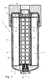
- Fig. 1 shows a longitudinal sectional view of an inventive oil filter 1 of an internal combustion engine, especially for motor vehicles.
- the oil filter 1 comprises a filter housing 17 with a motor-fixed housing upper part 26 and a housing lower part 27 screwed therein.
- an exchangeable filter cartridge 2 for filtering a passing oil flow.
- the lower housing part 27 and the filter cartridge 2 are formed substantially cylindrical, wherein they extend coaxially along a longitudinal axis 4.
- the filter cartridge 2 comprises a substantially cylindrical filter body 5 with two opposite in the axial direction end faces 6, 7. At the two end faces 6, 7 each have an end plate 8, 19 inextricably connected to the filter body 5.
- Radially inside the filter body 5 extends in the direction of the longitudinal axis 4, a grid-like support tube 23 which is held between the two end plates 8, 19, and which is exchanged as part of the filter cartridge 2 together with this.
- a tubular threaded connector 24 is screwed.
- the threaded connector 24 carries on its inside a double hexagon socket, by means of which it can be turned on or unscrewed.
- a circumferential collar 22 is integrally formed.
- the filter cartridge 2 is releasably pushed with this collar 22 sealingly on the freely projecting into the interior of the filter housing 18 peripheral surface of the threaded connector 24.
- the end plate 8 and the end plate 19 separate together with the collar 22 an outer raw side 28 of the filter cartridge 2 from an inner clean side 29 of the filter cartridge 2 and the oil filter 1.
- the oil filter 1 also has a filter bypass valve 3, which opens above a certain pressure difference between the raw side 28 and the clean side 29.
- a filter bypass valve 3 opens above a certain pressure difference between the raw side 28 and the clean side 29.
- Such increased pressure difference over normal operation may occur, for example, during cold start of the internal combustion engine, if the oil viscosity for a normal passage through the filter body 5 corresponding to the arrows 20 is too high.
- the oil flow, bypassing the filter body 5 enters the clean side 29 directly from the dirty side 28 through the filter bypass valve 3.
- the oil filter 1 is shown in its usual hanging mounting position, according to which the upper housing part 26 opposite lower end of the housing base 27 is in gravity below. There, the lower housing part 27 is provided with a drain valve 16, through which oil can be drained from the interior of the filter housing 17 during maintenance work.
- the filter bypass valve 3 and the drain valve 16 are arranged coaxially with the longitudinal axis 4.
- the filter bypass valve 3 and a valve body 15 ( Fig. 2 ) of the drain valve 16 firmly connected to the filter cartridge 2. Together with the filter cartridge 2, including its end disks 8, 19 and the support tube 23, they form a construction and maintenance unit, which is replaced in total at prescribed maintenance intervals.
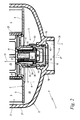
- Fig. 2 shows an enlarged detail view of the arrangement according to Fig. 1 in the region of the filter bypass valve 3 and the drain valve 16.
- the filter bypass valve 3 is arranged on the lower end disk 8 of the filter cartridge 2.
- a part of the filter bypass valve 3 is formed integrally with the end plate 8 as follows: Coaxially to the longitudinal axis 4 protrude in the axial direction of a cylindrical linear guide 12 and an outside at a distance the linear guide 12 enclosing sleeve 39, starting from the end plate 8 and from the clean side 29 out.
- an annular pressure surface 11 for a pressure spring 9 applied thereto is formed by the end plate 8, an annular pressure surface 11 for a pressure spring 9 applied thereto.
- the pressure surface 11, the linear guide 12 and the sleeve 39 are integrally formed with the end plate 8.
- a valve body 10 manufactured as a separate part is pushed onto the linear guide 12 and slidably guided on it in a coaxial manner.
- the compression spring 9 bears against the valve body 10 at its end opposite the pressure surface 11. By a biasing force of the compression spring 9, the valve body 10 is biased from the clean side forward parallel to the longitudinal axis 4.
- valve housing part 13 is provided with a conical valve seat 14 for the valve body 10.
- the valve housing part 13 with the valve seat 14 may be permanently and non-detachably connected to the end plate 8, for example, by welding, gluing or the like. It may also be expedient to mold the valve seat 14 in a section of the end disk 8.
- the valve housing part 13 is latchingly attached to the end plate.
- the sleeve 39 is provided with a circumferentially circumferential locking edge 35.
- the valve housing part 13 has latching tongues 34, which engage behind the latching edge 35 with an axial clearance a. As a result, the valve housing part 13 is held captive on the sleeve 39 of the end plate 8.
- the sleeve 39 is still provided on its peripheral side with a circumferential sealing ring 36 which seals the valve housing 13 on the output side of the valve seat 14 relative to the sleeve 39, but allows in conjunction with the axial play a relative movement of the valve housing part 13 relative to the sleeve 39.
- the valve housing part 13 is still provided on the inlet side of the valve seat 14 with windows 33, according to which the prevailing on the raw side 28 oil pressure on the outer or lower end face of the valve body 10 acts.
- the biasing force of the compression spring 9 is overcome, as a result of which the valve body 10 lifts off from its sealing seat 14 in the direction of an arrow 31 coaxially with the longitudinal axis 4.
- oil can pass directly through the windows 33 past the valve seat 14 in accordance with an arrow 32, bypassing the filter body 5, from the raw side 28 to the clean side 29.
- the housing part 27 is provided at its lower end in the direction of gravity with a arranged coaxially to the longitudinal axis 4 drain opening 37 and with a cylindrical, also arranged coaxially to the longitudinal axis 4 valve seat 18.
- a valve body 15 of the drain valve 16 carries at its lower end on its peripheral wall a circumferential sealing ring 30 which seals the valve body 15 relative to the valve seat 18 of the housing base 27. In this case, however, a relative movement of the valve body 15 is possible axially parallel to the longitudinal axis 4.
- the valve housing part 13 of the filter bypass valve 3 and the valve body 15 of the drain valve 16 are integrally formed, according to which the valve seat part 14 carrying the valve housing part 3 at the same time also forms the valve body 15 for the drain valve 16.
- the filter cartridge 2 due to the axial play a relative to the bottom of the housing base 27 perform an axial relative movement, without the valve body 10 of the filter bypass valve 3 lifts from its valve seat 14, and without the valve body 15 is pulled out of its operating position shown from the valve seat 18 , The tightness of the drain valve 16 and the reliability of the filter bypass valve 3 are permanently ensured.
- the lower housing part 27 is initially only partially removed from the upper housing part 26 (FIG. Fig. 1 ), wherein it performs relative to this an axial relative movement in the direction of the arrow 38. Since the filter cartridge 2 on the threaded connector 24 ( Fig. 1 ), this axial relative movement of the upper housing part 27 also takes place with respect to the filter cartridge 2, the filter bypass valve 3 integrated therein and the valve body 15 of the drainage valve 16. Since the valve body 15 is fixed by means of the latching tongue 34 on the filter cartridge 2, it is pulled out upon further screwing the housing base 27 from the cylindrical sealing seat 18, as a result, located in the interior of the filter housing 17 oil through the drain opening 37 can expire.
Landscapes
- Chemical & Material Sciences (AREA)
- Chemical Kinetics & Catalysis (AREA)
- Filtration Of Liquid (AREA)
- Lubrication Details And Ventilation Of Internal Combustion Engines (AREA)
Claims (9)
- Cartouche de filtre à huile (2) d'un moteur à combustion interne, notamment pour des véhicules automobiles, la cartouche de filtre à huile (2) présentant une soupape de dérivation de filtre (3) fixée sur elle de manière à ce que la cartouche de filtre à huile (2) forme, avec la soupape de dérivation de filtre (3), une unité modulaire prévue pour un échange commun, caractérisée en ce qu'une pièce de cage de soupape (13) portant un siège de soupape (14) pour un corps de soupape (10) de la soupape de dérivation de filtre (3) forme un corps de soupape (15) pour une soupape d'écoulement (16) d'un filtre à huile (1) et en ce que la pièce de cage de soupape (13) et le corps de soupape (15) forment un seul bloc.
- Cartouche de filtre à huile selon la revendication 1, caractérisée en ce que la cartouche de filtre à huile (2) présente un corps de filtre (5) essentiellement cylindrique, s'étendant le long d'un axe longitudinal (4) et comportant deux faces frontales opposées (6, 7), un disque d'extrémité (8) étant fixé, sur au moins l'une des faces frontales (6, 7), sur le corps de filtre (5) et la soupape de dérivation de filtre (3) étant placée sur le disque d'extrémité (8).
- Cartouche de filtre à huile selon la revendication 2, caractérisée en ce qu'au moins une partie de la soupape de dérivation de filtre (3) forme un seul bloc avec le disque d'extrémité (8).
- Cartouche de filtre à huile selon la revendication 3, caractérisée en ce que la soupape de dérivation de filtre (3) présente un corps de soupape (10) pouvant être déplacé en sens linéaire contre un ressort de pression (9), le ressort de pression (9) étant étayé contre une surface de pression (11) du disque d'extrémité (8).
- Cartouche de filtre à huile selon la revendication 4, caractérisée en ce que le corps de soupape (10) est guidé sur un rail linéaire (12) moulé sur le disque d'extrémité (8).
- Cartouche de filtre à huile selon la revendication 4 ou 5, caractérisée en ce qu'une pièce de cage de soupape (13) séparée avec un siège de soupape (14) pour le corps de soupape (10) est prévue et est fixée, notamment de manière encliquetable, sur le disque d'extrémité (8).
- Cartouche de filtre à huile selon l'une des revendications précédentes, caractérisée en ce que la pièce de cage de soupape (13) portant le siège de soupape (14) présente un jeu axial (a) par rapport au disque d'extrémité (8).
- Filtre à huile (1) d'un moteur à combustion interne, notamment pour des véhicules automobiles, comprenant une cartouche de filtre à huile (2), une soupape de dérivation de filtre (3) et un boîtier de filtre (17) destiné à réceptionner la cartouche de filtre à huile (2), le boîtier de filtre (17) présentant une soupape d'écoulement (16) et la cartouche de filtre à huile (2) formant, avec la soupape de dérivation de filtre (3), une unité modulaire prévue pour un échange commun, caractérisé en ce qu'une pièce de cage de soupape (13) de la soupape de dérivation de filtre (3) forme un corps de soupape (15) pour la soupape d'écoulement (16) du filtre à huile (1) et en ce que la pièce de cage de soupape (13) et le corps de soupape (15) forment un seul bloc.
- Filtre à huile selon la revendication 8, caractérisé en ce que la soupape de dérivation de filtre (3) et la soupape d'écoulement (16) sont disposées de manière coaxiale l'une par rapport à l'autre, le boîtier de filtre (17) présentant un siège de soupape (18) cylindrique pour le corps de soupape (15) de la soupape d'écoulement (16) et la pièce de cage de soupape (13) de la soupape de dérivation de filtre (3) présentant un jeu axial (a) par rapport à la cartouche de filtre à huile (2).
Applications Claiming Priority (1)
| Application Number | Priority Date | Filing Date | Title |
|---|---|---|---|
| DE202007017980U DE202007017980U1 (de) | 2007-12-20 | 2007-12-20 | Filterpatrone und Ölfilter eines Verbrennungsmotors |
Publications (2)
| Publication Number | Publication Date |
|---|---|
| EP2072103A1 EP2072103A1 (fr) | 2009-06-24 |
| EP2072103B1 true EP2072103B1 (fr) | 2012-06-20 |
Family
ID=40492595
Family Applications (1)
| Application Number | Title | Priority Date | Filing Date |
|---|---|---|---|
| EP08165912A Not-in-force EP2072103B1 (fr) | 2007-12-20 | 2008-10-06 | Cartouche de filtre et filtre à huile d'un moteur à combustion |
Country Status (2)
| Country | Link |
|---|---|
| EP (1) | EP2072103B1 (fr) |
| DE (1) | DE202007017980U1 (fr) |
Families Citing this family (9)
| Publication number | Priority date | Publication date | Assignee | Title |
|---|---|---|---|---|
| DE102010063822A1 (de) * | 2010-12-22 | 2012-06-28 | Hengst Gmbh & Co. Kg | Flüssigkeitsfilter mit einem Filterumgehungsventil |
| DE102013210065A1 (de) * | 2013-05-29 | 2014-12-04 | Mahle International Gmbh | Filtereinrichtung, insbesondere für ein Kraftfahrzeug |
| DE202014104029U1 (de) | 2014-08-28 | 2014-10-20 | Hengst Se & Co. Kg | Filter, der an einem Anschlussflansch anbaubar ist, und Filtereinsatz |
| DE102015103662A1 (de) | 2015-03-12 | 2016-09-15 | Hengst Se & Co. Kg | Filter mit einem Filterumgehungsventil und Filtereinsatz dafür |
| DE102017012016A1 (de) * | 2017-12-22 | 2019-06-27 | Mann+Hummel Gmbh | Filterelement eines Filters für Flüssigkeit, Ablassverschlusselement für eine Ablassöffnung eines Filtergehäuses und Filter |
| CN108087057A (zh) * | 2018-01-18 | 2018-05-29 | 广西玉林坤达机械制造有限责任公司 | 一种集成有旁通阀和放油阀的机油滤清器芯 |
| CN111228885B (zh) * | 2020-02-11 | 2022-06-21 | 江西众安职业危害评价检测有限公司 | 污水处理系统 |
| DE102023117941A1 (de) | 2023-07-07 | 2025-01-09 | Mann+Hummel Gmbh | Filterelement, Ablassverschlusselement und Filtersystem |
| DE102023117938A1 (de) | 2023-07-07 | 2025-01-09 | Mann+Hummel Gmbh | Ablassverschlusselement für ein Filtersystem, Filterelement und Filtersystem |
Family Cites Families (21)
| Publication number | Priority date | Publication date | Assignee | Title |
|---|---|---|---|---|
| GB532040A (en) * | 1939-08-14 | 1941-01-16 | Thomas Edward Aldham | A cartridge for an oil filter |
| US4815493A (en) * | 1987-09-17 | 1989-03-28 | Parker-Hannifin Corporation | Cartridge bypass valve |
| DE3903675A1 (de) * | 1989-02-08 | 1990-08-09 | Knecht Filterwerke Gmbh | Oelfilter zum reinigen von schmieroel |
| DE3904701A1 (de) * | 1989-02-16 | 1990-08-30 | Argo Feinmechanik | Filterelement fuer fluessigkeiten und gase |
| IT1237973B (it) * | 1990-02-09 | 1993-06-19 | Filtro olio di lubrificazione di motori a combustione interna per automezzi | |
| DE19605425C2 (de) * | 1995-03-16 | 1998-07-23 | Hengst Walter Gmbh & Co Kg | Flüssigkeitsfilter mit Filterumgehungsventil und filterelementseitiger Dichtfläche |
| DE19809989A1 (de) * | 1998-03-09 | 1999-09-16 | Mann & Hummel Filter | Ventil für eine Filteranordnung und ein Verfahren zu dessen Herstellung |
| WO2001007819A1 (fr) * | 1999-07-23 | 2001-02-01 | Filterwerk Mann+Hummel Gmbh | Raccord rapide pour l'ouverture d'une soupape |
| DE19961580A1 (de) * | 1999-12-21 | 2001-06-28 | Mann & Hummel Filter | Flüssigkeitsfilter mit Ablaß für Flüssigkeitsrückstände |
| DE10002118A1 (de) * | 2000-01-20 | 2001-07-26 | Mann & Hummel Filter | Ausgleichsbehälter eines Hydrauliksystems |
| DE20006974U1 (de) * | 2000-04-17 | 2001-08-23 | Ing. Walter Hengst GmbH & Co. KG, 48147 Münster | Flüssigkeitsfilter mit Sieb vor dem Filterumgehungsventil |
| DE10022873B4 (de) * | 2000-05-10 | 2008-06-26 | Mann + Hummel Gmbh | Filter |
| EP1199093A1 (fr) * | 2000-10-18 | 2002-04-24 | ARGO GmbH für Fluidtechnik | Elément filtrant |
| DE10103345A1 (de) * | 2001-01-25 | 2002-08-14 | Hermann Trabold | Filterpackung zum Filtern von flüssigen oder gasförmigen Medien |
| EP1440719A1 (fr) * | 2003-01-09 | 2004-07-28 | NTZ Nederland BV | Filtre de remplacement unidirectionnel et procédé associé |
| JP3793749B2 (ja) | 2002-11-15 | 2006-07-05 | トヨタ紡織株式会社 | エレメント交換型フィルタ及びそのドレン機構 |
| BRPI0411504B1 (pt) * | 2003-07-01 | 2013-09-17 | elemento filtrante, conjunto de cobertura, conjunto de filtro e processo para fixar e remover um elemento filtrante | |
| DE102004041290B4 (de) * | 2004-08-25 | 2016-06-02 | Volkswagen Ag | Filteranordnung mit Rückschlagventil |
| WO2006034448A1 (fr) * | 2004-09-20 | 2006-03-30 | Donaldson Company, Inc. | Configuration filtrante et procedes |
| FR2885819B1 (fr) * | 2005-05-20 | 2008-02-29 | Filtrauto Sa | Dispositif de vidange controlee d'un filtre a liquide |
| DE102006038100A1 (de) * | 2006-08-14 | 2008-02-21 | Mann + Hummel Gmbh | Filterelement, insbesondere zur Filtrierung von Flüssigkeiten oder Gasen |
-
2007
- 2007-12-20 DE DE202007017980U patent/DE202007017980U1/de not_active Expired - Lifetime
-
2008
- 2008-10-06 EP EP08165912A patent/EP2072103B1/fr not_active Not-in-force
Also Published As
| Publication number | Publication date |
|---|---|
| DE202007017980U1 (de) | 2009-04-30 |
| EP2072103A1 (fr) | 2009-06-24 |
Similar Documents
| Publication | Publication Date | Title |
|---|---|---|
| EP2072103B1 (fr) | Cartouche de filtre et filtre à huile d'un moteur à combustion | |
| DE60211323T2 (de) | Krafstofffilter mit umlaufventil | |
| DE112013005747B4 (de) | Filter, Filterelement, Filtergehäuse und Ablassvorrichtung eines Filters | |
| EP2881156B1 (fr) | Élément de filtre ayant un canal de dérivation ainsi qu'agencement de filtre doté d'un élément de filtre | |
| EP1136666A2 (fr) | Filtre pour liquide avec valve by-pass | |
| DE19605425A1 (de) | Flüssigkeitsfilter mit Filterumgehungsventil und filterelementseitiger Dichtfläche | |
| WO2014191476A1 (fr) | Élément filtrant et système de filtration muni d'un élément filtrant | |
| WO2007128306A2 (fr) | Filtre à liquide comprenant un clapet anti-retour situé dans le canal d'écoulement côté filtré | |
| WO2013178680A1 (fr) | Système de filtre | |
| EP2072768A1 (fr) | Filtre à huile d'un moteur à combustion interne et cartouche de filtre pour le filtre à huile | |
| DE102006029107B4 (de) | Filteranordnung mit einem Filtergehäuse und mit einem zylindrischen Filterelement | |
| DE29915844U1 (de) | Filter mit Ventil-Kombinationsbauteil | |
| DE202005007872U1 (de) | Filtereinrichtung, insbesondere zur Flüssigkeitsfilterung in Brennkraftmaschinen | |
| WO2015078687A1 (fr) | Élément de filtre et système de filtre avec filtrage de courant parallèle | |
| EP3067102B1 (fr) | Separateur d'eau et systeme de separation d'eau comprenant un dispositif d'evacuation d'eau integre | |
| WO2015150443A1 (fr) | Filtre pour l'huile lubrifiante d'une machine à combustion interne et insert de filtre pour le filtre | |
| EP2808071B1 (fr) | Dispositif de filtre, en particulier pour un véhicule automobile | |
| WO2005007267A1 (fr) | Ensemble filtre a huile et element filtrant | |
| EP1879679B1 (fr) | Dispositif filtrant destine, en particulier a filtrer un liquide dans des moteurs a combustion interne | |
| DE102016000339B4 (de) | Filterelement und Filtersystem für ein Flüssigmedium mit rein- und rohseitiger Entlüftung | |
| EP2129902B1 (fr) | Filtre pour liquides | |
| DE102010005334B4 (de) | Flüssigkeitsfilter | |
| DE102020114107A1 (de) | Separater Ventilsitz | |
| EP3727641B1 (fr) | Système de filtration comportant un clapet anti-retour et un élément filtrant | |
| DE29917563U1 (de) | Fluidfilter mit gehäusefestem Ablassdom |
Legal Events
| Date | Code | Title | Description |
|---|---|---|---|
| PUAI | Public reference made under article 153(3) epc to a published international application that has entered the european phase |
Free format text: ORIGINAL CODE: 0009012 |
|
| AK | Designated contracting states |
Kind code of ref document: A1 Designated state(s): AT BE BG CH CY CZ DE DK EE ES FI FR GB GR HR HU IE IS IT LI LT LU LV MC MT NL NO PL PT RO SE SI SK TR |
|
| AX | Request for extension of the european patent |
Extension state: AL BA MK RS |
|
| 17P | Request for examination filed |
Effective date: 20090811 |
|
| 17Q | First examination report despatched |
Effective date: 20090903 |
|
| AKX | Designation fees paid |
Designated state(s): AT BE BG CH CY CZ DE DK EE ES FI FR GB GR HR HU IE IS IT LI LT LU LV MC MT NL NO PL PT RO SE SI SK TR |
|
| GRAP | Despatch of communication of intention to grant a patent |
Free format text: ORIGINAL CODE: EPIDOSNIGR1 |
|
| GRAS | Grant fee paid |
Free format text: ORIGINAL CODE: EPIDOSNIGR3 |
|
| GRAA | (expected) grant |
Free format text: ORIGINAL CODE: 0009210 |
|
| AK | Designated contracting states |
Kind code of ref document: B1 Designated state(s): AT BE BG CH CY CZ DE DK EE ES FI FR GB GR HR HU IE IS IT LI LT LU LV MC MT NL NO PL PT RO SE SI SK TR |
|
| REG | Reference to a national code |
Ref country code: GB Ref legal event code: FG4D Free format text: NOT ENGLISH |
|
| REG | Reference to a national code |
Ref country code: CH Ref legal event code: EP |
|
| REG | Reference to a national code |
Ref country code: AT Ref legal event code: REF Ref document number: 562678 Country of ref document: AT Kind code of ref document: T Effective date: 20120715 |
|
| REG | Reference to a national code |
Ref country code: IE Ref legal event code: FG4D Free format text: LANGUAGE OF EP DOCUMENT: GERMAN |
|
| REG | Reference to a national code |
Ref country code: DE Ref legal event code: R096 Ref document number: 502008007467 Country of ref document: DE Effective date: 20120823 |
|
| PG25 | Lapsed in a contracting state [announced via postgrant information from national office to epo] |
Ref country code: SE Free format text: LAPSE BECAUSE OF FAILURE TO SUBMIT A TRANSLATION OF THE DESCRIPTION OR TO PAY THE FEE WITHIN THE PRESCRIBED TIME-LIMIT Effective date: 20120620 Ref country code: FI Free format text: LAPSE BECAUSE OF FAILURE TO SUBMIT A TRANSLATION OF THE DESCRIPTION OR TO PAY THE FEE WITHIN THE PRESCRIBED TIME-LIMIT Effective date: 20120620 Ref country code: LT Free format text: LAPSE BECAUSE OF FAILURE TO SUBMIT A TRANSLATION OF THE DESCRIPTION OR TO PAY THE FEE WITHIN THE PRESCRIBED TIME-LIMIT Effective date: 20120620 Ref country code: NO Free format text: LAPSE BECAUSE OF FAILURE TO SUBMIT A TRANSLATION OF THE DESCRIPTION OR TO PAY THE FEE WITHIN THE PRESCRIBED TIME-LIMIT Effective date: 20120920 |
|
| REG | Reference to a national code |
Ref country code: NL Ref legal event code: VDEP Effective date: 20120620 |
|
| REG | Reference to a national code |
Ref country code: LT Ref legal event code: MG4D Effective date: 20120620 |
|
| PG25 | Lapsed in a contracting state [announced via postgrant information from national office to epo] |
Ref country code: HR Free format text: LAPSE BECAUSE OF FAILURE TO SUBMIT A TRANSLATION OF THE DESCRIPTION OR TO PAY THE FEE WITHIN THE PRESCRIBED TIME-LIMIT Effective date: 20120620 Ref country code: SI Free format text: LAPSE BECAUSE OF FAILURE TO SUBMIT A TRANSLATION OF THE DESCRIPTION OR TO PAY THE FEE WITHIN THE PRESCRIBED TIME-LIMIT Effective date: 20120620 Ref country code: GR Free format text: LAPSE BECAUSE OF FAILURE TO SUBMIT A TRANSLATION OF THE DESCRIPTION OR TO PAY THE FEE WITHIN THE PRESCRIBED TIME-LIMIT Effective date: 20120921 Ref country code: LV Free format text: LAPSE BECAUSE OF FAILURE TO SUBMIT A TRANSLATION OF THE DESCRIPTION OR TO PAY THE FEE WITHIN THE PRESCRIBED TIME-LIMIT Effective date: 20120620 |
|
| PG25 | Lapsed in a contracting state [announced via postgrant information from national office to epo] |
Ref country code: EE Free format text: LAPSE BECAUSE OF FAILURE TO SUBMIT A TRANSLATION OF THE DESCRIPTION OR TO PAY THE FEE WITHIN THE PRESCRIBED TIME-LIMIT Effective date: 20120620 Ref country code: IS Free format text: LAPSE BECAUSE OF FAILURE TO SUBMIT A TRANSLATION OF THE DESCRIPTION OR TO PAY THE FEE WITHIN THE PRESCRIBED TIME-LIMIT Effective date: 20121020 Ref country code: RO Free format text: LAPSE BECAUSE OF FAILURE TO SUBMIT A TRANSLATION OF THE DESCRIPTION OR TO PAY THE FEE WITHIN THE PRESCRIBED TIME-LIMIT Effective date: 20120620 Ref country code: SK Free format text: LAPSE BECAUSE OF FAILURE TO SUBMIT A TRANSLATION OF THE DESCRIPTION OR TO PAY THE FEE WITHIN THE PRESCRIBED TIME-LIMIT Effective date: 20120620 Ref country code: CY Free format text: LAPSE BECAUSE OF FAILURE TO SUBMIT A TRANSLATION OF THE DESCRIPTION OR TO PAY THE FEE WITHIN THE PRESCRIBED TIME-LIMIT Effective date: 20120620 Ref country code: CZ Free format text: LAPSE BECAUSE OF FAILURE TO SUBMIT A TRANSLATION OF THE DESCRIPTION OR TO PAY THE FEE WITHIN THE PRESCRIBED TIME-LIMIT Effective date: 20120620 |
|
| PG25 | Lapsed in a contracting state [announced via postgrant information from national office to epo] |
Ref country code: PL Free format text: LAPSE BECAUSE OF FAILURE TO SUBMIT A TRANSLATION OF THE DESCRIPTION OR TO PAY THE FEE WITHIN THE PRESCRIBED TIME-LIMIT Effective date: 20120620 Ref country code: PT Free format text: LAPSE BECAUSE OF FAILURE TO SUBMIT A TRANSLATION OF THE DESCRIPTION OR TO PAY THE FEE WITHIN THE PRESCRIBED TIME-LIMIT Effective date: 20121022 |
|
| PG25 | Lapsed in a contracting state [announced via postgrant information from national office to epo] |
Ref country code: NL Free format text: LAPSE BECAUSE OF FAILURE TO SUBMIT A TRANSLATION OF THE DESCRIPTION OR TO PAY THE FEE WITHIN THE PRESCRIBED TIME-LIMIT Effective date: 20120620 |
|
| PLBE | No opposition filed within time limit |
Free format text: ORIGINAL CODE: 0009261 |
|
| STAA | Information on the status of an ep patent application or granted ep patent |
Free format text: STATUS: NO OPPOSITION FILED WITHIN TIME LIMIT |
|
| BERE | Be: lapsed |
Owner name: MANN+HUMMEL G.M.B.H. Effective date: 20121031 |
|
| PG25 | Lapsed in a contracting state [announced via postgrant information from national office to epo] |
Ref country code: ES Free format text: LAPSE BECAUSE OF FAILURE TO SUBMIT A TRANSLATION OF THE DESCRIPTION OR TO PAY THE FEE WITHIN THE PRESCRIBED TIME-LIMIT Effective date: 20121001 Ref country code: DK Free format text: LAPSE BECAUSE OF FAILURE TO SUBMIT A TRANSLATION OF THE DESCRIPTION OR TO PAY THE FEE WITHIN THE PRESCRIBED TIME-LIMIT Effective date: 20120620 |
|
| 26N | No opposition filed |
Effective date: 20130321 |
|
| PG25 | Lapsed in a contracting state [announced via postgrant information from national office to epo] |
Ref country code: MC Free format text: LAPSE BECAUSE OF NON-PAYMENT OF DUE FEES Effective date: 20121031 |
|
| REG | Reference to a national code |
Ref country code: CH Ref legal event code: PL |
|
| GBPC | Gb: european patent ceased through non-payment of renewal fee |
Effective date: 20121006 |
|
| REG | Reference to a national code |
Ref country code: DE Ref legal event code: R097 Ref document number: 502008007467 Country of ref document: DE Effective date: 20130321 |
|
| REG | Reference to a national code |
Ref country code: IE Ref legal event code: MM4A |
|
| PG25 | Lapsed in a contracting state [announced via postgrant information from national office to epo] |
Ref country code: GB Free format text: LAPSE BECAUSE OF NON-PAYMENT OF DUE FEES Effective date: 20121006 Ref country code: CH Free format text: LAPSE BECAUSE OF NON-PAYMENT OF DUE FEES Effective date: 20121031 Ref country code: IE Free format text: LAPSE BECAUSE OF NON-PAYMENT OF DUE FEES Effective date: 20121006 Ref country code: BE Free format text: LAPSE BECAUSE OF NON-PAYMENT OF DUE FEES Effective date: 20121031 Ref country code: BG Free format text: LAPSE BECAUSE OF FAILURE TO SUBMIT A TRANSLATION OF THE DESCRIPTION OR TO PAY THE FEE WITHIN THE PRESCRIBED TIME-LIMIT Effective date: 20120920 Ref country code: LI Free format text: LAPSE BECAUSE OF NON-PAYMENT OF DUE FEES Effective date: 20121031 |
|
| PG25 | Lapsed in a contracting state [announced via postgrant information from national office to epo] |
Ref country code: MT Free format text: LAPSE BECAUSE OF FAILURE TO SUBMIT A TRANSLATION OF THE DESCRIPTION OR TO PAY THE FEE WITHIN THE PRESCRIBED TIME-LIMIT Effective date: 20120620 |
|
| PG25 | Lapsed in a contracting state [announced via postgrant information from national office to epo] |
Ref country code: TR Free format text: LAPSE BECAUSE OF FAILURE TO SUBMIT A TRANSLATION OF THE DESCRIPTION OR TO PAY THE FEE WITHIN THE PRESCRIBED TIME-LIMIT Effective date: 20120620 |
|
| PG25 | Lapsed in a contracting state [announced via postgrant information from national office to epo] |
Ref country code: LU Free format text: LAPSE BECAUSE OF NON-PAYMENT OF DUE FEES Effective date: 20121006 |
|
| PG25 | Lapsed in a contracting state [announced via postgrant information from national office to epo] |
Ref country code: HU Free format text: LAPSE BECAUSE OF FAILURE TO SUBMIT A TRANSLATION OF THE DESCRIPTION OR TO PAY THE FEE WITHIN THE PRESCRIBED TIME-LIMIT Effective date: 20081006 |
|
| REG | Reference to a national code |
Ref country code: AT Ref legal event code: MM01 Ref document number: 562678 Country of ref document: AT Kind code of ref document: T Effective date: 20131006 |
|
| PG25 | Lapsed in a contracting state [announced via postgrant information from national office to epo] |
Ref country code: AT Free format text: LAPSE BECAUSE OF NON-PAYMENT OF DUE FEES Effective date: 20131006 |
|
| REG | Reference to a national code |
Ref country code: FR Ref legal event code: PLFP Year of fee payment: 8 |
|
| PGFP | Annual fee paid to national office [announced via postgrant information from national office to epo] |
Ref country code: DE Payment date: 20151022 Year of fee payment: 8 Ref country code: IT Payment date: 20151028 Year of fee payment: 8 |
|
| PGFP | Annual fee paid to national office [announced via postgrant information from national office to epo] |
Ref country code: FR Payment date: 20151023 Year of fee payment: 8 |
|
| REG | Reference to a national code |
Ref country code: DE Ref legal event code: R119 Ref document number: 502008007467 Country of ref document: DE |
|
| REG | Reference to a national code |
Ref country code: FR Ref legal event code: ST Effective date: 20170630 |
|
| PG25 | Lapsed in a contracting state [announced via postgrant information from national office to epo] |
Ref country code: FR Free format text: LAPSE BECAUSE OF NON-PAYMENT OF DUE FEES Effective date: 20161102 Ref country code: DE Free format text: LAPSE BECAUSE OF NON-PAYMENT OF DUE FEES Effective date: 20170503 |
|
| PG25 | Lapsed in a contracting state [announced via postgrant information from national office to epo] |
Ref country code: IT Free format text: LAPSE BECAUSE OF NON-PAYMENT OF DUE FEES Effective date: 20161006 |