EP2072199A2 - Scie circulaire - Google Patents
Scie circulaire Download PDFInfo
- Publication number
- EP2072199A2 EP2072199A2 EP08020552A EP08020552A EP2072199A2 EP 2072199 A2 EP2072199 A2 EP 2072199A2 EP 08020552 A EP08020552 A EP 08020552A EP 08020552 A EP08020552 A EP 08020552A EP 2072199 A2 EP2072199 A2 EP 2072199A2
- Authority
- EP
- European Patent Office
- Prior art keywords
- circular saw
- saw blade
- machine part
- saw according
- bearing
- Prior art date
- Legal status (The legal status is an assumption and is not a legal conclusion. Google has not performed a legal analysis and makes no representation as to the accuracy of the status listed.)
- Granted
Links
Images

Classifications
-
- B—PERFORMING OPERATIONS; TRANSPORTING
- B27—WORKING OR PRESERVING WOOD OR SIMILAR MATERIAL; NAILING OR STAPLING MACHINES IN GENERAL
- B27B—SAWS FOR WOOD OR SIMILAR MATERIAL; COMPONENTS OR ACCESSORIES THEREFOR
- B27B9/00—Portable power-driven circular saws for manual operation
- B27B9/02—Arrangements for adjusting the cutting depth or the amount of tilting
Definitions
- the present invention relates to a circular saw, in particular an electric circular plunge saw, with a base part, a machine part comprising a driven saw blade, and an adjusting device by means of which the saw blade for adjusting a desired depth of cut relative to the base part adjusted, in particular pivoted, can be.
- Circular saws with adjustable cutting depth sometimes offer the possibility of pre-scratching.
- the saw blade is adjusted to such a small depth of cut that the workpiece to be machined is scratched only superficially.
- the circular saw is moved with this preset scoring cutting depth according to the desired cutting line.
- the actual saw cut is done with deeply dipped saw blade along the pre-scored line. By pre-scoring a tearing or splintering of the workpiece surface can be avoided.
- pre-scoring cut line and saw cut line slightly differ from each other.
- the saw cut is done outside the pre-scored area, so that the pre-scored line is largely ineffective. It can therefore come with conventional circular saws despite pre-scoring to a ripping of the workpiece surface.
- the object of the invention is to provide a portable circular saw, in which this problem does not occur.
- the adjusting device displaces the saw blade when a predetermined cutting depth, in particular a scoring cutting depth, is exceeded, transversely to the working direction with respect to the base part.
- the cutting plane defined by the saw blade is tilted by a free-cutting angle with respect to a working direction of the portable circular saw.
- the adjusting device displaces the saw blade by a predetermined amount. This may, for example, be the amount which corresponds to the discrepancy between the scoring line and the saw cut line on the surface of the workpiece at a certain cutting depth which is particularly relevant for practice.
- the predetermined amount of the transverse offset may in particular be about 1/10 mm to a few tenths of a millimeter.
- An expedient embodiment of the invention provides that the amount of the transverse offset is independent of the extent of exceeding the predetermined cutting depth. This results, for example, in a simple changeover between the two basic operating modes "pre-scoring” and “sawing".
- the amount of the transverse offset varies depending on the degree of exceeding the predetermined cutting depth. This way can be considered the circular shape of the saw blade an exact adjustment of the cutting line to the current cutting depth done.
- the amount of transverse offset is determined such that the line of intersection of the offset saw blade, i. the cut formed by the offset saw blade in the workpiece, at least substantially congruent with the cutting line of the unsplit saw blade, i. with the cut formed by the unsupported saw blade in the workpiece is. This ensures that the saw cut is made within the pre-scored area, thus avoiding tearing of the workpiece edges.
- the adjusting device comprises a positive control for the machine part, which converts the adjustment movement of the machine part in the transverse displacement movement of the machine part with respect to the base part.
- a further advantageous embodiment of the invention provides that the machine part is articulated via a pivot bearing with transverse to the direction of rotation pivot axis on the base part, wherein the machine part in the pivot bearing has at least one of the amount of the transverse offset corresponding axial clearance.
- Swivel bearings of this type are often provided in circular saws with adjustable cutting depth, so that the targeted provision of an axial clearance in a particularly simple and cost-effective manner can allow a transverse offset.
- the machine part is biased against the transverse displacement direction. This ensures that the saw blade at a Resetting the cutting depth from saw cut depth to scoring cut depth or to a home position returns to its original position.
- the pivot bearing preferably has a bearing section which comprises a restoring device, in particular a spring, against the restoring force of which the transverse offset movement of the machine part takes place.
- a restoring device in particular a spring
- Such a return device on the pivot bearing of the machine part allows a particularly simple embodiment of the bias.
- the pivot bearing on a bearing portion comprising a base part-side control surface and a machine part-side control surface, which cooperate in a pivoting of the machine part and force the transverse displacement movement of the machine part.
- a further preferred embodiment of the invention is that the base part-side control surface is formed on a bearing block of the base part and the machine-part-side control surface on a bearing block of the machine part. Since bearing blocks are often present on circular saws of the type mentioned, they can be used advantageously for the provision of control surfaces.
- the bearing block of the base part and / or the bearing block of the machine part is provided with a separate, rotatably mounted bearing disc on which the one control surface is formed.
- a separate bearing disc makes it possible to optimize the properties of one of the control surfaces by appropriate selection of materials, for example in terms of durability or frictional resistance.
- the control parameters for example the maximum transverse offset, can be easily changed by replacing the bearing disk.
- control surfaces are designed such that essentially only one state with unadjusted saw blade or a state with offset by a single predetermined amount saw blade can be produced. This allows a simple changeover between the two basic operating modes "pre-scoring” and "sawing".
- control surfaces are designed such that intermediate states can be produced between a state with an unadjusted saw blade and a state offset by a predetermined maximum amount saw blade, in which the amount of the transverse offset is less than the maximum transverse offset
- the amount of transverse offset increases steadily with increasing depth of cut.
- the one control surface on at least one projecting in the axial direction of the cam, which is in response to the relative position between the machine part and the base part with a recess formed in the other control surface in or out of engagement.
- the cam engages the recess until it reaches the predetermined cutting depth and is disengaged when the predetermined cutting depth is exceeded with the recess. An annoying or unnecessary transverse offset before reaching the predetermined cutting depth is thereby avoided.
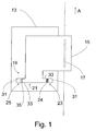
- a circular saw which is schematically illustrated in plan view, is an electric plunge-type circular saw which comprises a base part 13, a machine part 15 and an adjusting device 19.
- the machine part 15 comprises an electric motor (not shown) and a saw blade 17 driven by it.
- the machine part 15 is articulated to the base part 13 via a pivot bearing 21, wherein the pivot axis 41 (FIG. FIGS. 3A and 3B ) is aligned transversely to the indicated by an arrow working direction A of the circular saw.
- the working direction A is predetermined, for example, by a stop device provided on the base part 13, which interacts with a workpiece edge or a guide aid, or by a target device, by means of which a user aligns the portable circular saw with a marking (tear) applied to the workpiece.
- a stop device provided on the base part 13, which interacts with a workpiece edge or a guide aid, or by a target device, by means of which a user aligns the portable circular saw with a marking (tear) applied to the workpiece.
- the cutting plane defined by the saw blade 17 is tilted with respect to the working direction A by a so-called free-cutting angle, which is why the axis of rotation of the saw blade 17 is not exactly perpendicular to the working direction A.
- the tilt around the clearance angle is in the simplified representation of Fig. 1 Not shown.
- the clearance angle is exaggerated for clarity.
- pivot axis 41 extends parallel to the axis of rotation of the saw blade 17 and thus also not exactly perpendicular to the working direction A.
- the pivot axis 41 can run exactly perpendicular to the working direction A, so that the clearance angle of the saw blade 17 to others Way is realized.
- a motor unit arranged in the machine part 15 can be correspondingly rotated for the saw blade 17 in order to ensure the free-cutting position of the saw blade 17.
- the circular saw is equipped with a scoring function, that is, the immersion depth can be limited to a value corresponding to a superficial scoring of the workpiece by the saw blade 17.
- the saw blade 17 After deactivating the scribing function, for example by releasing the associated cutting depth limiting device, the saw blade 17 can be dipped deeper into the workpiece so as to perform a saw cut.
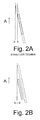
- Fig. 2A schematically illustrated situation.
- the saw blade dips into the workpiece, so that the small area of the workpiece surface, indicated by a solid line, is processed by the saw blade.
- the cutting line S is processed by the saw blade and the cutting line S 'results.
- the cutting lines S and S ' are offset relative to each other due to the clearance angle, that is, the cutting line S' of the dipped saw blade is displaced from the cutting line S of the scoring saw blade toward the workpiece side to be used.
- the saw cut is not completely within the pre-scored area, so scoring is largely ineffective.
- the same problem arises when, for example, due to manufacturing tolerances or a relatively large bearing clearance a - actually desired - exact alignment of the saw blade parallel to the working direction of the machine is not given.
- the saw blade offset transversely to the working direction A with respect to the base part of the circular saw when the scoring cut depth is exceeded it can be achieved that the cutting lines S and S 'are congruent and the effect of scoring fully comes into play.
- the type of offset can be such that there is only one set, corresponding to the pre-scoring threshold depth and a fixed amount of transverse offset, so that the amount of the transverse offset of the extent of exceeding the scoring cut depth is independent.
- it can also be provided to adapt the transverse offset in one or more intermediate steps or in a continuous manner to the cutting line which shifts according to the depth of cut.
- the transverse offset occurs simultaneously with the dipping motion without requiring user action.
- Such a forced control for the machine part 15, which converts the pivoting movement into a suitable transverse offset movement with respect to the base part 13, can be realized in a simple manner by providing a movement latitude transversely to the working direction A in the already existing pivot bearing 21 of the portable circular saw.
- the machine part 15 in the pivot bearing 21 a deliberately selected axial clearance, which here corresponds to the maximum amount of the transverse offset.
- the pivot bearing 21 of the circular saw on a bearing portion 23 and a bearing portion 25.
- Both bearing sections 23, 25 are each formed by a bearing block 31 of the base part 13 and a bearing block 33 of the machine part 15, which together store a pivot pin, not shown.
- a return device 24th between the bearing block 31 of the base part 13 and the bearing block 33 of the machine part 15, which biases the machine part 15 against the transverse displacement direction in the direction of the bearing portion 25.
- the return device 24 is shown in the drawing as a helical spring. Alternatively, it may also be a diaphragm spring or the like.
- a separate bearing plate 35 which may be made of a suitable material.
- FIGS. 3A and 3B represent the bearing portion 25 in more detail.
- a base part-side control surface 27 and a machine part-side control surface 29 is formed, which slide against each other and thereby cooperate in a pivoting of the machine part 15.
- the control surfaces 27, 29 are not flat, but that in the base part-side control surface 27, a cam 37 and in the machine part-side control surface 29, a recess 39 is formed.
- the machine part 15 of the cam 37 is in engagement with the recess 39 or disengaged.
- the cam 37 according to Fig. 3A is engaged with the recess 39
- the machine part 15 is in the unset position.
- the cam 37 according to Fig. 3B moved out of engagement with the recess 39, the machine part 15 is pressed against the spring bias in the direction of the bearing portion 23, resulting in a transverse offset of the machine part 15 results in Fig. 3B denoted by D.
- the cam 37 and the recess 39 are matched to one another in such a way that, starting from the basic position of the machine part 15, they engage until reaching the predetermined cutting depth and only disengage when the predetermined cutting depth is exceeded.
- control surfaces 27, 29 provide essentially only two states, which correspond to no transverse offset and a maximum transverse offset D.
- the cam 37 and the recess 39 have a smooth running profile to allow an optimized sliding movement in the transition from the unset to the staggered state.
- a compensating transverse offset of the machine part 15 is effected during the dipping movement, so that the saw cut is oriented exactly on the pre-scored line and tearing of the workpiece edges is prevented.
- the user does not have to be careful to consider the exact transverse offset, for example, by adjusting or resetting it, since the compensation takes place automatically in the course of the pivoting movement.
- This advantageous function can be provided in a simple and cost-effective manner by providing the existing pivoting device of a portable circular saw with a controllable axial play.
Landscapes
- Life Sciences & Earth Sciences (AREA)
- Engineering & Computer Science (AREA)
- Mechanical Engineering (AREA)
- Wood Science & Technology (AREA)
- Forests & Forestry (AREA)
- Sawing (AREA)
Applications Claiming Priority (1)
| Application Number | Priority Date | Filing Date | Title |
|---|---|---|---|
| DE200710060711 DE102007060711A1 (de) | 2007-12-17 | 2007-12-17 | Handkreissäge |
Publications (3)
| Publication Number | Publication Date |
|---|---|
| EP2072199A2 true EP2072199A2 (fr) | 2009-06-24 |
| EP2072199A3 EP2072199A3 (fr) | 2012-08-15 |
| EP2072199B1 EP2072199B1 (fr) | 2013-09-25 |
Family
ID=40459752
Family Applications (1)
| Application Number | Title | Priority Date | Filing Date |
|---|---|---|---|
| EP20080020552 Active EP2072199B1 (fr) | 2007-12-17 | 2008-11-26 | Scie circulaire |
Country Status (3)
| Country | Link |
|---|---|
| EP (1) | EP2072199B1 (fr) |
| DE (1) | DE102007060711A1 (fr) |
| ES (1) | ES2435542T3 (fr) |
Family Cites Families (4)
| Publication number | Priority date | Publication date | Assignee | Title |
|---|---|---|---|---|
| US3242953A (en) * | 1964-05-08 | 1966-03-29 | Black & Decker Mfg Co | Shoe plate alining means for portable power-driven saw |
| DE3635159C2 (de) * | 1986-10-16 | 1998-05-07 | Bosch Gmbh Robert | Handwerkzeugmaschine mit einer Auflageplatte und einem Parallelanschlag |
| DE4123315A1 (de) * | 1990-01-18 | 1993-01-14 | Reich Maschf Gmbh Karl | Handkreissaege zum trennen von beschichteten werkstuecken aus holz o. dgl. |
| DE20100725U1 (de) * | 2001-01-16 | 2001-03-08 | Mafell AG, 78727 Oberndorf | Handkreissäge |
-
2007
- 2007-12-17 DE DE200710060711 patent/DE102007060711A1/de not_active Ceased
-
2008
- 2008-11-26 EP EP20080020552 patent/EP2072199B1/fr active Active
- 2008-11-26 ES ES08020552T patent/ES2435542T3/es active Active
Also Published As
| Publication number | Publication date |
|---|---|
| EP2072199B1 (fr) | 2013-09-25 |
| EP2072199A3 (fr) | 2012-08-15 |
| ES2435542T3 (es) | 2013-12-20 |
| DE102007060711A1 (de) | 2009-06-25 |
Similar Documents
| Publication | Publication Date | Title |
|---|---|---|
| DE69405655T2 (de) | Kappsäge mit Parallelogramkonstruktion | |
| DE69736034T2 (de) | Schneidblatt- und Motorträger mit Höhe/Winkel-Einstellvorrichtung | |
| DE69825643T2 (de) | Gehrungssägeschwenklagerfestspannvorrichtung | |
| DE2825023C2 (fr) | ||
| EP1551214B1 (fr) | Barre de coupe | |
| EP1180416A2 (fr) | Outil électroportatif à dispositif de serrage rapide | |
| DE602004010334T2 (de) | Schlittengeführte Gehrungssäge | |
| DE4008533A1 (de) | Entgratmesser zum entgraten von ebenen und unebenen bohrungsraendern | |
| DE112023000461T5 (de) | Schienensäge | |
| DE10152910A1 (de) | Schälgerät mit schwenkbarem Schälkopf | |
| CH694852A5 (de) | Werkzeugmaschine fuer Trennarbeiten. | |
| EP1955800A2 (fr) | Scie à onglet | |
| DE60018026T2 (de) | Sägeblattpositioniervorrichtung für Tischsäge | |
| EP2251130A1 (fr) | Dispositif de levage pour une lame de scie d'une machine destinée au traitement de pièces usinées en bois, en matière synthétique et analogues | |
| CH684687A5 (de) | Schneidwerkzeug. | |
| EP2072199B1 (fr) | Scie circulaire | |
| EP4364915B1 (fr) | Machine d'usinage électrique | |
| DE2741648A1 (de) | Anordnung der vorschubwalzen an bandmesser-spaltmaschinen | |
| EP1666179A2 (fr) | Plaquette de coupe pour le décolletage et tronçonnage des pièces et porte plaquette | |
| DE202008001744U1 (de) | Kappsäge mit Neigungsverstellung | |
| DE3130686C2 (de) | Handbearbeitungsgerät | |
| DE202019103190U1 (de) | Lochsägenanordnung für eine Bohrmaschine und Horizontallochsäge für eine Lochsägenanordnung | |
| DE4025440A1 (de) | Tischsaege | |
| DE29704465U1 (de) | Schneidvorrichtung für Papier, Folien o.dgl. | |
| DE69403591T2 (de) | Kombinierte Tisch- und Gehrungssäge |
Legal Events
| Date | Code | Title | Description |
|---|---|---|---|
| PUAI | Public reference made under article 153(3) epc to a published international application that has entered the european phase |
Free format text: ORIGINAL CODE: 0009012 |
|
| AK | Designated contracting states |
Kind code of ref document: A2 Designated state(s): AT BE BG CH CY CZ DE DK EE ES FI FR GB GR HR HU IE IS IT LI LT LU LV MC MT NL NO PL PT RO SE SI SK TR |
|
| AX | Request for extension of the european patent |
Extension state: AL BA MK RS |
|
| PUAL | Search report despatched |
Free format text: ORIGINAL CODE: 0009013 |
|
| AK | Designated contracting states |
Kind code of ref document: A3 Designated state(s): AT BE BG CH CY CZ DE DK EE ES FI FR GB GR HR HU IE IS IT LI LT LU LV MC MT NL NO PL PT RO SE SI SK TR |
|
| AX | Request for extension of the european patent |
Extension state: AL BA MK RS |
|
| RIC1 | Information provided on ipc code assigned before grant |
Ipc: B23D 45/16 20060101ALI20120710BHEP Ipc: B27B 9/02 20060101AFI20120710BHEP |
|
| 17P | Request for examination filed |
Effective date: 20120830 |
|
| GRAP | Despatch of communication of intention to grant a patent |
Free format text: ORIGINAL CODE: EPIDOSNIGR1 |
|
| AKX | Designation fees paid |
Designated state(s): AT BE BG CH CY CZ DE DK EE ES FI FR GB GR HR HU IE IS IT LI LT LU LV MC MT NL NO PL PT RO SE SI SK TR |
|
| INTG | Intention to grant announced |
Effective date: 20130404 |
|
| GRAS | Grant fee paid |
Free format text: ORIGINAL CODE: EPIDOSNIGR3 |
|
| GRAA | (expected) grant |
Free format text: ORIGINAL CODE: 0009210 |
|
| AK | Designated contracting states |
Kind code of ref document: B1 Designated state(s): AT BE BG CH CY CZ DE DK EE ES FI FR GB GR HR HU IE IS IT LI LT LU LV MC MT NL NO PL PT RO SE SI SK TR |
|
| REG | Reference to a national code |
Ref country code: GB Ref legal event code: FG4D Free format text: NOT ENGLISH |
|
| REG | Reference to a national code |
Ref country code: CH Ref legal event code: EP Ref country code: CH Ref legal event code: NV Representative=s name: DR. GRAF AND PARTNER AG INTELLECTUAL PROPERTY, CH |
|
| REG | Reference to a national code |
Ref country code: AT Ref legal event code: REF Ref document number: 633519 Country of ref document: AT Kind code of ref document: T Effective date: 20131015 |
|
| REG | Reference to a national code |
Ref country code: IE Ref legal event code: FG4D Free format text: LANGUAGE OF EP DOCUMENT: GERMAN |
|
| REG | Reference to a national code |
Ref country code: DE Ref legal event code: R096 Ref document number: 502008010714 Country of ref document: DE Effective date: 20131121 |
|
| REG | Reference to a national code |
Ref country code: ES Ref legal event code: FG2A Ref document number: 2435542 Country of ref document: ES Kind code of ref document: T3 Effective date: 20131220 |
|
| PG25 | Lapsed in a contracting state [announced via postgrant information from national office to epo] |
Ref country code: HR Free format text: LAPSE BECAUSE OF FAILURE TO SUBMIT A TRANSLATION OF THE DESCRIPTION OR TO PAY THE FEE WITHIN THE PRESCRIBED TIME-LIMIT Effective date: 20130925 Ref country code: LT Free format text: LAPSE BECAUSE OF FAILURE TO SUBMIT A TRANSLATION OF THE DESCRIPTION OR TO PAY THE FEE WITHIN THE PRESCRIBED TIME-LIMIT Effective date: 20130925 Ref country code: SE Free format text: LAPSE BECAUSE OF FAILURE TO SUBMIT A TRANSLATION OF THE DESCRIPTION OR TO PAY THE FEE WITHIN THE PRESCRIBED TIME-LIMIT Effective date: 20130925 Ref country code: NO Free format text: LAPSE BECAUSE OF FAILURE TO SUBMIT A TRANSLATION OF THE DESCRIPTION OR TO PAY THE FEE WITHIN THE PRESCRIBED TIME-LIMIT Effective date: 20131225 |
|
| REG | Reference to a national code |
Ref country code: NL Ref legal event code: VDEP Effective date: 20130925 |
|
| REG | Reference to a national code |
Ref country code: LT Ref legal event code: MG4D |
|
| PG25 | Lapsed in a contracting state [announced via postgrant information from national office to epo] |
Ref country code: LV Free format text: LAPSE BECAUSE OF FAILURE TO SUBMIT A TRANSLATION OF THE DESCRIPTION OR TO PAY THE FEE WITHIN THE PRESCRIBED TIME-LIMIT Effective date: 20130925 Ref country code: GR Free format text: LAPSE BECAUSE OF FAILURE TO SUBMIT A TRANSLATION OF THE DESCRIPTION OR TO PAY THE FEE WITHIN THE PRESCRIBED TIME-LIMIT Effective date: 20131226 Ref country code: FI Free format text: LAPSE BECAUSE OF FAILURE TO SUBMIT A TRANSLATION OF THE DESCRIPTION OR TO PAY THE FEE WITHIN THE PRESCRIBED TIME-LIMIT Effective date: 20130925 Ref country code: SI Free format text: LAPSE BECAUSE OF FAILURE TO SUBMIT A TRANSLATION OF THE DESCRIPTION OR TO PAY THE FEE WITHIN THE PRESCRIBED TIME-LIMIT Effective date: 20130925 |
|
| PG25 | Lapsed in a contracting state [announced via postgrant information from national office to epo] |
Ref country code: CZ Free format text: LAPSE BECAUSE OF FAILURE TO SUBMIT A TRANSLATION OF THE DESCRIPTION OR TO PAY THE FEE WITHIN THE PRESCRIBED TIME-LIMIT Effective date: 20130925 Ref country code: EE Free format text: LAPSE BECAUSE OF FAILURE TO SUBMIT A TRANSLATION OF THE DESCRIPTION OR TO PAY THE FEE WITHIN THE PRESCRIBED TIME-LIMIT Effective date: 20130925 Ref country code: NL Free format text: LAPSE BECAUSE OF FAILURE TO SUBMIT A TRANSLATION OF THE DESCRIPTION OR TO PAY THE FEE WITHIN THE PRESCRIBED TIME-LIMIT Effective date: 20130925 Ref country code: IS Free format text: LAPSE BECAUSE OF FAILURE TO SUBMIT A TRANSLATION OF THE DESCRIPTION OR TO PAY THE FEE WITHIN THE PRESCRIBED TIME-LIMIT Effective date: 20140125 Ref country code: SK Free format text: LAPSE BECAUSE OF FAILURE TO SUBMIT A TRANSLATION OF THE DESCRIPTION OR TO PAY THE FEE WITHIN THE PRESCRIBED TIME-LIMIT Effective date: 20130925 Ref country code: RO Free format text: LAPSE BECAUSE OF FAILURE TO SUBMIT A TRANSLATION OF THE DESCRIPTION OR TO PAY THE FEE WITHIN THE PRESCRIBED TIME-LIMIT Effective date: 20130925 |
|
| PG25 | Lapsed in a contracting state [announced via postgrant information from national office to epo] |
Ref country code: CY Free format text: LAPSE BECAUSE OF FAILURE TO SUBMIT A TRANSLATION OF THE DESCRIPTION OR TO PAY THE FEE WITHIN THE PRESCRIBED TIME-LIMIT Effective date: 20130925 Ref country code: PL Free format text: LAPSE BECAUSE OF FAILURE TO SUBMIT A TRANSLATION OF THE DESCRIPTION OR TO PAY THE FEE WITHIN THE PRESCRIBED TIME-LIMIT Effective date: 20130925 |
|
| BERE | Be: lapsed |
Owner name: MAFELL A.G. Effective date: 20131130 |
|
| REG | Reference to a national code |
Ref country code: DE Ref legal event code: R097 Ref document number: 502008010714 Country of ref document: DE |
|
| PG25 | Lapsed in a contracting state [announced via postgrant information from national office to epo] |
Ref country code: PT Free format text: LAPSE BECAUSE OF FAILURE TO SUBMIT A TRANSLATION OF THE DESCRIPTION OR TO PAY THE FEE WITHIN THE PRESCRIBED TIME-LIMIT Effective date: 20140127 |
|
| PG25 | Lapsed in a contracting state [announced via postgrant information from national office to epo] |
Ref country code: MC Free format text: LAPSE BECAUSE OF FAILURE TO SUBMIT A TRANSLATION OF THE DESCRIPTION OR TO PAY THE FEE WITHIN THE PRESCRIBED TIME-LIMIT Effective date: 20130925 |
|
| PLBE | No opposition filed within time limit |
Free format text: ORIGINAL CODE: 0009261 |
|
| STAA | Information on the status of an ep patent application or granted ep patent |
Free format text: STATUS: NO OPPOSITION FILED WITHIN TIME LIMIT |
|
| REG | Reference to a national code |
Ref country code: IE Ref legal event code: MM4A |
|
| 26N | No opposition filed |
Effective date: 20140626 |
|
| PG25 | Lapsed in a contracting state [announced via postgrant information from national office to epo] |
Ref country code: BE Free format text: LAPSE BECAUSE OF NON-PAYMENT OF DUE FEES Effective date: 20131130 Ref country code: DK Free format text: LAPSE BECAUSE OF FAILURE TO SUBMIT A TRANSLATION OF THE DESCRIPTION OR TO PAY THE FEE WITHIN THE PRESCRIBED TIME-LIMIT Effective date: 20130925 |
|
| REG | Reference to a national code |
Ref country code: DE Ref legal event code: R097 Ref document number: 502008010714 Country of ref document: DE Effective date: 20140626 |
|
| PG25 | Lapsed in a contracting state [announced via postgrant information from national office to epo] |
Ref country code: IE Free format text: LAPSE BECAUSE OF NON-PAYMENT OF DUE FEES Effective date: 20131126 |
|
| REG | Reference to a national code |
Ref country code: ES Ref legal event code: FD2A Effective date: 20150331 |
|
| PG25 | Lapsed in a contracting state [announced via postgrant information from national office to epo] |
Ref country code: ES Free format text: LAPSE BECAUSE OF NON-PAYMENT OF DUE FEES Effective date: 20131127 |
|
| PG25 | Lapsed in a contracting state [announced via postgrant information from national office to epo] |
Ref country code: TR Free format text: LAPSE BECAUSE OF FAILURE TO SUBMIT A TRANSLATION OF THE DESCRIPTION OR TO PAY THE FEE WITHIN THE PRESCRIBED TIME-LIMIT Effective date: 20130925 |
|
| PG25 | Lapsed in a contracting state [announced via postgrant information from national office to epo] |
Ref country code: HU Free format text: LAPSE BECAUSE OF FAILURE TO SUBMIT A TRANSLATION OF THE DESCRIPTION OR TO PAY THE FEE WITHIN THE PRESCRIBED TIME-LIMIT; INVALID AB INITIO Effective date: 20081126 Ref country code: BG Free format text: LAPSE BECAUSE OF FAILURE TO SUBMIT A TRANSLATION OF THE DESCRIPTION OR TO PAY THE FEE WITHIN THE PRESCRIBED TIME-LIMIT Effective date: 20130925 Ref country code: LU Free format text: LAPSE BECAUSE OF NON-PAYMENT OF DUE FEES Effective date: 20131126 |
|
| PG25 | Lapsed in a contracting state [announced via postgrant information from national office to epo] |
Ref country code: MT Free format text: LAPSE BECAUSE OF FAILURE TO SUBMIT A TRANSLATION OF THE DESCRIPTION OR TO PAY THE FEE WITHIN THE PRESCRIBED TIME-LIMIT Effective date: 20130925 |
|
| REG | Reference to a national code |
Ref country code: FR Ref legal event code: PLFP Year of fee payment: 8 |
|
| REG | Reference to a national code |
Ref country code: FR Ref legal event code: PLFP Year of fee payment: 9 |
|
| REG | Reference to a national code |
Ref country code: FR Ref legal event code: PLFP Year of fee payment: 10 |
|
| PGFP | Annual fee paid to national office [announced via postgrant information from national office to epo] |
Ref country code: IT Payment date: 20171124 Year of fee payment: 10 |
|
| PG25 | Lapsed in a contracting state [announced via postgrant information from national office to epo] |
Ref country code: IT Free format text: LAPSE BECAUSE OF NON-PAYMENT OF DUE FEES Effective date: 20181126 |
|
| PGFP | Annual fee paid to national office [announced via postgrant information from national office to epo] |
Ref country code: GB Payment date: 20231123 Year of fee payment: 16 |
|
| PGFP | Annual fee paid to national office [announced via postgrant information from national office to epo] |
Ref country code: FR Payment date: 20231120 Year of fee payment: 16 Ref country code: CH Payment date: 20231201 Year of fee payment: 16 Ref country code: AT Payment date: 20231121 Year of fee payment: 16 |
|
| REG | Reference to a national code |
Ref country code: CH Ref legal event code: PL |
|
| REG | Reference to a national code |
Ref country code: AT Ref legal event code: MM01 Ref document number: 633519 Country of ref document: AT Kind code of ref document: T Effective date: 20241126 Ref country code: CH Ref legal event code: PL |
|
| GBPC | Gb: european patent ceased through non-payment of renewal fee |
Effective date: 20241126 |
|
| PG25 | Lapsed in a contracting state [announced via postgrant information from national office to epo] |
Ref country code: CH Free format text: LAPSE BECAUSE OF NON-PAYMENT OF DUE FEES Effective date: 20241130 |
|
| PG25 | Lapsed in a contracting state [announced via postgrant information from national office to epo] |
Ref country code: AT Free format text: LAPSE BECAUSE OF NON-PAYMENT OF DUE FEES Effective date: 20241126 |
|
| PG25 | Lapsed in a contracting state [announced via postgrant information from national office to epo] |
Ref country code: GB Free format text: LAPSE BECAUSE OF NON-PAYMENT OF DUE FEES Effective date: 20241126 |
|
| PG25 | Lapsed in a contracting state [announced via postgrant information from national office to epo] |
Ref country code: FR Free format text: LAPSE BECAUSE OF NON-PAYMENT OF DUE FEES Effective date: 20241130 |
|
| PGFP | Annual fee paid to national office [announced via postgrant information from national office to epo] |
Ref country code: DE Payment date: 20260128 Year of fee payment: 18 |