EP2072267A2 - Transportvorrichtung für zu bedruckende flache Güter - Google Patents
Transportvorrichtung für zu bedruckende flache Güter Download PDFInfo
- Publication number
- EP2072267A2 EP2072267A2 EP08019317A EP08019317A EP2072267A2 EP 2072267 A2 EP2072267 A2 EP 2072267A2 EP 08019317 A EP08019317 A EP 08019317A EP 08019317 A EP08019317 A EP 08019317A EP 2072267 A2 EP2072267 A2 EP 2072267A2
- Authority
- EP
- European Patent Office
- Prior art keywords
- printing
- transport
- printing module
- conveyor belt
- printed
- Prior art date
- Legal status (The legal status is an assumption and is not a legal conclusion. Google has not performed a legal analysis and makes no representation as to the accuracy of the status listed.)
- Granted
Links
- 238000007639 printing Methods 0.000 claims abstract description 74
- 238000000465 moulding Methods 0.000 claims description 6
- 238000007641 inkjet printing Methods 0.000 abstract description 2
- 230000032258 transport Effects 0.000 description 50
- 230000005484 gravity Effects 0.000 description 4
- 238000004519 manufacturing process Methods 0.000 description 4
- 238000003825 pressing Methods 0.000 description 3
- 238000012546 transfer Methods 0.000 description 3
- 230000005540 biological transmission Effects 0.000 description 2
- 238000004140 cleaning Methods 0.000 description 2
- 238000003780 insertion Methods 0.000 description 2
- 230000037431 insertion Effects 0.000 description 2
- 238000007789 sealing Methods 0.000 description 2
- 210000001015 abdomen Anatomy 0.000 description 1
- 239000000969 carrier Substances 0.000 description 1
- 239000003795 chemical substances by application Substances 0.000 description 1
- 238000010276 construction Methods 0.000 description 1
- 230000008878 coupling Effects 0.000 description 1
- 238000010168 coupling process Methods 0.000 description 1
- 238000005859 coupling reaction Methods 0.000 description 1
- 238000013461 design Methods 0.000 description 1
- 238000011161 development Methods 0.000 description 1
- 230000018109 developmental process Effects 0.000 description 1
- 230000000694 effects Effects 0.000 description 1
- 238000011156 evaluation Methods 0.000 description 1
- 238000000034 method Methods 0.000 description 1
- 238000012545 processing Methods 0.000 description 1
Images
Classifications
-
- G—PHYSICS
- G07—CHECKING-DEVICES
- G07B—TICKET-ISSUING APPARATUS; FARE-REGISTERING APPARATUS; FRANKING APPARATUS
- G07B17/00—Franking apparatus
- G07B17/00459—Details relating to mailpieces in a franking system
- G07B17/00467—Transporting mailpieces
-
- B—PERFORMING OPERATIONS; TRANSPORTING
- B41—PRINTING; LINING MACHINES; TYPEWRITERS; STAMPS
- B41J—TYPEWRITERS; SELECTIVE PRINTING MECHANISMS, i.e. MECHANISMS PRINTING OTHERWISE THAN FROM A FORME; CORRECTION OF TYPOGRAPHICAL ERRORS
- B41J11/00—Devices or arrangements of selective printing mechanisms, e.g. ink-jet printers or thermal printers, for supporting or handling copy material in sheet or web form
- B41J11/007—Conveyor belts or like feeding devices
-
- B—PERFORMING OPERATIONS; TRANSPORTING
- B41—PRINTING; LINING MACHINES; TYPEWRITERS; STAMPS
- B41J—TYPEWRITERS; SELECTIVE PRINTING MECHANISMS, i.e. MECHANISMS PRINTING OTHERWISE THAN FROM A FORME; CORRECTION OF TYPOGRAPHICAL ERRORS
- B41J13/00—Devices or arrangements of selective printing mechanisms, e.g. ink-jet printers or thermal printers, specially adapted for supporting or handling copy material in short lengths, e.g. sheets
- B41J13/10—Sheet holders, retainers, movable guides, or stationary guides
- B41J13/12—Sheet holders, retainers, movable guides, or stationary guides specially adapted for small cards, envelopes, or the like, e.g. credit cards, cut visiting cards
-
- B—PERFORMING OPERATIONS; TRANSPORTING
- B41—PRINTING; LINING MACHINES; TYPEWRITERS; STAMPS
- B41J—TYPEWRITERS; SELECTIVE PRINTING MECHANISMS, i.e. MECHANISMS PRINTING OTHERWISE THAN FROM A FORME; CORRECTION OF TYPOGRAPHICAL ERRORS
- B41J3/00—Typewriters or selective printing or marking mechanisms characterised by the purpose for which they are constructed
- B41J3/407—Typewriters or selective printing or marking mechanisms characterised by the purpose for which they are constructed for marking on special material
-
- G—PHYSICS
- G07—CHECKING-DEVICES
- G07B—TICKET-ISSUING APPARATUS; FARE-REGISTERING APPARATUS; FRANKING APPARATUS
- G07B17/00—Franking apparatus
- G07B17/00185—Details internally of apparatus in a franking system, e.g. franking machine at customer or apparatus at post office
- G07B17/00193—Constructional details of apparatus in a franking system
-
- G—PHYSICS
- G07—CHECKING-DEVICES
- G07B—TICKET-ISSUING APPARATUS; FARE-REGISTERING APPARATUS; FRANKING APPARATUS
- G07B17/00—Franking apparatus
- G07B17/00459—Details relating to mailpieces in a franking system
- G07B17/00508—Printing or attaching on mailpieces
- G07B2017/00516—Details of printing apparatus
- G07B2017/00524—Printheads
- G07B2017/00532—Inkjet
Definitions
- the invention relates to a transport device for flat goods to be printed according to the preamble of claim 1.
- the invention is used in microprocessor-controlled printing devices and is suitable for franking machines and other mail processing devices.
- the invention makes it possible to achieve a small offset of the dots in the printing, which in particular improves the machine readability of an impression of a franked mailpiece.
- a transport principle with an overhead belt and a bottom-mounted sprung counter-pressure device, between which a mailpiece is clamped, is known from the patent DD 233 101 B5
- a thermal transfer ribbon is not suitable as a conveyor belt.
- the thermal transfer ribbon is disposed above a feed table over which the mail pieces are transported horizontally post-downstream.
- the feed table has openings through which a driven counter-pressure roller passes through the mail item.
- a second printing position for printing franking strips is provided, which are rolled up on rolls and which are unrolled for printing.
- This second printing path causes higher production costs.
- a printing device for an ink-jet franking machine has already been proposed, wherein a franking print is printed by means of an ink-jet print head on a mail piece in the case of an approximately horizontal letter transport.
- the ink jet printhead is arranged to be stationary behind a guide plate in a recess for printing.
- As a transport device is a revolving conveyor belt, which is also arranged on the side of the guide plate.
- a supporting and pressing device is arranged with a plurality of rollers, so that a fed mail piece between the rollers of the support and pressure device and the circulating conveyor belt is clamped.
- the device can not avoid skewing the print carrier. Even an insufficiently tensioned conveyor belt or not exactly parallel alignment of the axes of those rollers on which the conveyor belt rotates, carries the aforementioned danger in itself. Due to the large number of roles of support and pressure device latter is very expensive.
- JetMail ® In the DE 196 05 015 C1 ( US 5,949,444 ) an embodiment for a printing device of an ink-jet franking machine JetMail ® has been proposed by the applicant Francotyp-Postalia AG & Co., at a non-horizontal approximately vertical letter transport performs a franking pressure by means of an ink jet printhead, which is arranged behind a guide plate in a recess stationary.
- a transport device is a revolving conveyor belt with pressure elements for the mail pieces (letters to 20 mm thickness, DIN B4 format) or for franking strips, which are formed aufklebbar on packets of any thickness.
- the print carrier (letter, packet, franking strip) is clamped between the pressure elements and the guide plate.
- An apparatus for character printing on a predetermined place on one side of a flat recording medium and a correspondingly equipped franking machine are known.
- a transport belt is arranged on the one hand on the inkjet printhead side and on the other hand forms a non-suspended support means for the print side of a flat recording medium (object, mail, envelope).
- a counter-pressure device supports the flat object from below, in which a belt rolls around at least two other rollers, at least one of which is not suspended.
- One from the EP 1 170 141 B1 Known device for printing a print carrier in the printing area uses in the power transmission area a driven transport drum and non-driven counter-pressure rollers or alternatively a non-driven counter-pressure conveyor belt.
- a stationary ink jet printhead prints in the print area the downstream moving print carrier, wherein the ink jet print head is arranged axially to the transport drum.
- the printing area is preferably about 1 inch and is spaced from the power transmission area, wherein the distance of the farthest pixel from the edge of the transport drum is smaller than the radius of the circumference of the transport drum.
- the disadvantage is the low approximately linear contact of the mail piece surface to be printed with the transport drum and a spaced feed wheel for mailpieces.
- the feed wheel is driven by a toothed belt from the transport drum. This causes a ⁇ x offset of the dots in the print image. Othogonal this results in a ⁇ y offset of the dots in the printed image, especially in very large mailpieces.
- the structure also causes high manufacturing costs. In the market segment of franking machines with small to medium Mailgut pensatz a compact transport device for mail pieces with the lowest possible production costs is required.
- the invention has for its object to develop a transport device of a printing device for flat goods, which ensures a high print quality at a mean throughput of flat goods in cooperation with a microprocessor-controlled printing device.
- the reliability of the printing device should be as high as possible and the printing offset in the x-direction and y-direction should be low.
- postcards and on the other hand C4 and B4 letters with a mail piece thickness up to 10 mm are to be processed.
- a printing position is achieved.
- the printing module is held in the printing position and a transport device is arranged to horizontally transport flat goods or a mail piece past the print head.
- the transport device is stationarily arranged in the printing device with respect to a pressure device which presses the mail piece to the conveyor belt.
- the conveyor belt acts in the transport area with a predetermined stiction on a part of the surface of the mail piece, which is not printed, but is located near the area to be printed.
- a printing module is arranged counter to the direction of gravity over a printing window in the z direction of a Cartesian coordinate system.
- a print image is generated by at least one print head.
- at least one print head of an ink cartridge ejects ink droplets opposite to the z direction in the direction of gravity through the print window.
- the printing window is arranged on the edge of a conveyor belt in a housing part, wherein the conveyor belt transports a flat good to be printed on the edge during printing in the transport direction x past the at least one print head.
- the flat goods are pressed against the force of gravity to the conveyor belt in a support area.
- a support region is advantageous, which is located on both sides of a line, which is centered through the printing window transversely to the transport direction x in the y-direction of the Cartesian coordinate system runs, stretched.
- the conveyor belt is supported on a support plate, which is arranged above the transport region between a molding plate and a bearing plate of a roller carrier, wherein the support surface of the support plate is larger than the surface of the pressure window, which is adjacent to the support plate.
- the printing device is arranged in a box-shaped chassis.
- the box-shaped construction ensures a high stability with a very simple structure.
- the transport device for flat goods to be printed has a printing module in the printing position, from which the printing module can be moved in a conventional manner into a cleaning and sealing position by transverse movement means known per se transversely to the mailpiece transport direction.
- the cleaning and sealing position can advantageously be arranged closer to the conveyor belt. This also reduced the size of the chassis and housing across the mailpiece transport direction.
- the conveyor belt is preferably a driven wide tensioned flat belt.
- the latter is guided by means of deflection rollers both over the printing module and under the printing module along, while the printing module is in a printing position. In the printing position, the printing module protrudes at least partially into the intermediate space between the two deflection rollers, but the heads of the two ink cartridges continue to be outside the transport area.
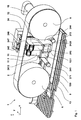
- FIG. 1 Figure 3 is a perspective view of a flat goods transport device with a print module in a printing position.
- the transport device 1 is an essential part of a franking machine and is arranged above a feed table 13.
- a - not shown - from below resiliently pressing device is arranged below the feed table and acts through an opening 130 through the feed through in the z-direction.
- a franking machine is known, inter alia, from a - not shown - electronic part (meters) and the mail piece transport device with a - not shown - electronic control.
- a keyboard and a display unit of the meter are connected to the electronic part, not shown.
- the electronic controller is electrically connected to a drive 19 of the mail piece transport device for driving them.
- the transport device 1 has a conveyor belt 2, which is designed as a flat belt.
- the flat belt operates in the transport area with a predetermined stiction on a part of the surface of the flat goods or mailpieces, which is not printed, but is close to the printing area.
- the flat belt of the mailpiece transport device has a large transverse rigidity and is guided over two pulleys 5 and 6.
- the flat belt on the one hand passes under the pressure module and is on the other hand returned via the printing module.
- the printing module is known to consist of a print carriage 24, a - not shown - contacting and control electronics on the back of the print carriage 24, and at least one print head, for example, an ink cartridge with integrated inkjet printhead.
- the print carriage 24 contributes in the example shown Fig. 1 preferably two ink cartridges 11, 12, which are offset from one another in the x and y directions. Alternatively, several ink cartridges are possible.
- the print carriage 24 each has an opening 2410, 2420 for inserting the ink cartridges 11, 12, which is bounded laterally by a right and left side plate 244 and 243 and the bottom side by a carrier molding and the back by a contact field of contacting and control electronics.
- the carrier molding consists of two halves, wherein a first half 241 is provided with a first opening 2410 for insertion of the first ink cartridge 11 and a second half 242 with a second opening 2420 for insertion of the second ink cartridge 12 and offset in the x direction to the first half ,
- the first carrier molding half 241 is offset in the y-direction to the second half.
- Each opening is closed at the top by a closing lever 247, 248 per cartridge.
- the printing module protrudes in the printing position in the space between the guide rollers 5 and 6, wherein the ink jet print heads of the two ink cartridges 11, 12 are located outside the transport area and arranged above a - not shown - pressure window against the direction of gravity in the z direction of a Cartesian coordinate system are.
- the bellies 11.1, 12.1 of the two ink cartridges 11, 12 are located within the space between the guide rollers 5 and 6 above a support plate.
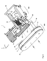
- FIG. 2 a perspective view of the transport device is shown in exploded view. It is envisaged that the conveyor belt 2 is supported on the support plate, which is arranged above the transport region between a molding plate 21 and a bearing plate 22 of a roller carrier 20B.
- the support surface of the support plate is here greater than the area of a (non-visible) printing window, which is opposite to the at least one ink jet print head.
- the pressure window is arranged adjacent to the support plate in a table top of the feed table 13 in the y-direction offset from the opening 130, through which a resiliently pressing from below pressure device (not shown) protrudes, which is arranged below the feed table.
- the printing carriage 24 of the printing module is accordingly adapted to slide on two slide bars 271, 272, which are fixed on the rear side to a rear wall 25 of a box-shaped chassis 20A and the front side to a bearing plate 22 of a roller carrier 20B for the pulleys the roller carrier 20B with the deflection rollers 5 and 6 and with the conveyor belt 2 is a removable from the chassis 20A and replaceable part of the transport device 1.
- the drive 19 for example, an electric motor with gear, fixed and acts drivingly directly on the shaft of the guide roller 5 a.
- the driver 19 may be attached to the box-shaped chassis 20A (not shown).
- the shaft of the drive 19 and the shaft of the guide roller 5 are then coupled to each other via coupling means.
Landscapes
- Physics & Mathematics (AREA)
- General Physics & Mathematics (AREA)
- Ink Jet (AREA)
- Handling Of Sheets (AREA)
- Handling Of Continuous Sheets Of Paper (AREA)
Abstract
Description
- Die Erfindung betrifft eine Transportvorrichtung für zu bedruckende flache Güter gemäß des Oberbegriffs des Anspruchs 1. Die Erfindung kommt in mikroprozessorgesteuerten Druckvorrichtungen zum Einsatz und ist für Frankiermaschinen und andere Postverarbeitungsgeräte geeignet. Die Erfindung gestattet es, einen geringen Versatz der Dots beim Drucken zu erreichen, was insbesondere die Maschinenlesbarkeit eines Abdruckes eines frankierten Poststückes verbessert.
- Ein Transportprinzip mit einem oben liegenden Band und einer unten angeordneten gefederten Gegendruckvorrichtung, zwischen welchen ein Poststück eingeklemmt wird, ist aus der Patentschrift
DD 233 101 B5 - Aus der Patentschrift
US 6.550.994 B2 ist eine Frankiermaschine mit einer Poststücktransportvorrichtung bekannt, mit welcher die Briefe mittels eines oben liegenden Transportbandes und mehreren unten angeordneten gefederten Hebeln durch die Frankiermaschine transportiert werden. Ähnliches geht auch ausUS 5.813.326 ,US 6.776.089 B1 undUS 6.585.433 B2 hervor. Das Transportband ist auf Rollen schleifenförmig gelagert und erlaubt kein Hineinragen des Druckmoduls oder eines Teils davon in den Bereich zwischen den Rollen. Die Weite des Transportbandes ist relativ klein und entspricht etwa 1 Zoll. Die Ausdehnung des Gehäuses quer zur Poststücktransportrichtung ist dem gegenüber relativ groß. Hinzu kommt, dass eine zweite Druckposition für das Bedrucken Frankierstreifen vorgesehen ist, die auf Rollen aufgerollt sind und die zum Bedrucken abgerollt werden. Dieser zweite Druckpfad verursacht höhere Herstellungskosten.
ImUS 5.467.709 wurde bereits eine Druckvorrichtung für eine Ink-Jet-Frankiermaschine vorgeschlagen, wobei auf ein Poststück bei einem annähernd waagerechten Brieftransport ein Frankierdruck mittels eines Tintenstrahldruckkopfs aufgedruckt wird. Der Tintenstrahldruckkopf ist zum Drucken hinter einer Führungsplatte in einer Ausnehmung stationär angeordnet. Als Transportvorrichtung dient ein umlaufendes Transportband, welches ebenfalls auf der Seite der Führungsplatte angeordnet ist. Auf der anderen Seite gegenüber der Führungsplatte ist eine Stütz- und Andruckvorrichtung mit mehreren Rollen angeordnet, so dass ein zugeführtes Poststück zwischen den Rollen der Stütz- und Andruckvorrichtung und dem umlaufenden Transportband eingeklemmt wird. Die Vorrichtung kann aber ein Schieflaufen der Druckträger nicht vermeiden. Schon ein ungenügend gespanntes Transportband oder eine nicht exakt parallele Ausrichtung der Achsen von denjenigen Rollen, auf welchen das Transportband umläuft, birgt die vorgenannte Gefahr in sich. Durch die Vielzahl der Rollen der Stütz- und Andruckvorrichtung ist letztere sehr aufwendig.
In derDE 196 05 015 C1 (US 5.949.444 ) ist bereits eine Ausführung für eine Druckvorrichtung einer Ink-Jet-Frankiermaschine JetMail® der Anmelderin Francotyp-Postalia AG & Co. vorgeschlagen worden, die bei einem nichtwaagerechten annähernd vertikalen Brieftransport einen Frankierdruck mittels einem Tintenstrahldruckkopf durchführt, der hinter einer Führungsplatte in einer Ausnehmung stationär angeordnet ist. Als Transportvorrichtung dient ein umlaufendes Transportband mit Andruckelementen für die Poststücke (Briefe bis 20 mm Dicke, DIN B4-Format) oder für Frankierstreifen, die auf Päckchen beliebiger Dicke aufklebbar ausgebildet sind. Der Druckträger (Brief, Päckchen, Frankierstreifen) wird zwischen den Andruckelementen und der Führungsplatte eingeklemmt.
Es wurden auch schon einfacher aufgebaute Transport- und Antriebsvorrichtungen ohne Gegendruckvorrichtung (DE 196 05 014 C1 ) oder mit Gegendruckvorrichtung (WO 99/44174 WO 99/44174 - Aus dem
EP 1 079 975 B1 ist eine Vorrichtung zum Zeichendrucken auf einem vorbestimmten Platz einer Seite eines flachen Aufzeichnungsträgers und eine entsprechend ausgestattete Frankiermaschine bekannt. Ein Transport-Riemen ist einerseits auf der Tintenstrahl-Druckkopf-Seite angeordnet und bildet andererseits ein nicht aufgehängtes Stützmittel für die zu bedruckende Seite eines flachen Aufzeichnungsträgers (Objektes, Postgut, Kuvert). Eine Gegendruckvorrichtung stützt das flache Objekt von unten ab, in welcher ein Riemen sich um mindestens zwei andere Rollen rollt, von denen mindestens eine nicht aufgehängt ist.
Eine aus demEP 1 170 141 B1 bekannte Vorrichtung zum Bedrucken eines Druckträgers im Druckbereich nutzt im Kraftübertragungsbereich eine angetriebene Transporttrommel und nicht angetriebene Gegendruckrollen bzw. alternativ ein nicht angetriebenes Gegendruckförderband. Ein stationärer Tintenstrahldruckkopf bedruckt im Druckbereich den stromabwärts bewegten Druckträger, wobei der Tintenstrahldruckkopf axial zur Transporttrommel angeordnet ist. Der Druckbereich beträgt vorzugsweise ca. 1 Zoll und ist vom Kraftübertragungsbereich beabstandet, wobei der Abstand des entferntesten Pixels vom Rand der Transporttrommel kleiner als der Radius des Umfanges der Transporttrommel ist. Nachteilig sind aber der geringe näherungsweise linienförmige Kontakt der zu bedruckenden Poststückoberfläche mit der Transporttrommel und ein im Abstand angeordnetes Einzugsrad für Poststücke. Das Einzugsrad wird über einen Zahnriemen von der Transporttrommel angetrieben. Das verursacht einen Δx-Versatz der Dots im Druckbild. Othogonal dazu ergibt sich ein Δy-Versatz der Dots im Druckbild, insbesondere bei sehr großformatigen Poststücken. Der Aufbau verursacht außerdem hohe Herstellungskosten.
Im Marktsegment der Frankiermaschinen mit kleinen bis mittleren Postgutdurchsatz wird eine kompakte Transportvorrichtung für Poststücke bei möglichst geringen Herstellungskosten benötigt. - Der Erfindung liegt die Aufgabe zugrunde, eine Transportvorrichtung einer Druckvorrichtung für flache Güter zu entwickeln, die im Zusammenwirken mit einer mikroprozessorgesteuerten Druckvorrichtung eine hohe Druckqualität bei einem mittleren Durchsatz flacher Güter gewährleistet.
- Trotz geringer Herstellungskosten soll die Zuverlässigkeit der Druckvorrichtung möglichst hoch und der Druckversatz in x-Richtung und y-Richtung sollte gering sein. Dabei sollen einerseits Postkarten und andererseits C4 und B4 Briefe mit einer Poststückdicke bis 10 mm verarbeitet werden.
- Die Aufgabe wird mit den Merkmalen der Anordnung nach dem Anspruch 1 gelöst.
- Durch eine Querbewegung eines Druckmoduls quer zur Poststücktransportrichtung mittels Querbewegungsmittel wird eine Druckposition erreicht. Beim Drucken nach einem Tintenstrahldruckverfahren wird das Druckmodul in der Druckposition gehalten und eine Transportvorrichtung ist entsprechend angeordnet, um flache Güter bzw. ein Poststück am Druckkopf vorbei waagerecht zu transportieren. Die Transportvorrichtung ist ortsfest in der Druckvorrichtung gegenüber einer Andruckvorrichtung angeordnet, welche das Poststück an das Transportband andrückt.
Das Transportband wirkt im Transportbereich mit einer vorbestimmten Haftreibung auf einen Teil der Oberfläche der Poststückes, welcher nicht bedruckt wird, aber nahe dem zu bedruckenden Bereich gelegen ist.
Ein Druckmodul ist entgegen der Schwerkraftrichtung über einem Druckfenster in z-Richtung eines kartesischen Koordinatensystems angeordnet. Beim Drucken wird durch mindestens einen Druckkopf ein Druckbild erzeugt. Beispielsweise stößt mindestens ein Druckkopf einer Tintenkartusche Tintentropfen entgegengesetzt zur z-Richtung in Schwerkraftrichtung durch das Druckfenster aus. Das Druckfenster ist am Rand eines Transportbandes in einem Gehäuseteil angeordnet, wobei das Transportband ein am Rande zu bedruckendes flaches Gut während des Druckens in Transportrichtung x an dem mindestens einen Druckkopf vorbei transportiert. Die flachen Güter werden entgegen der Schwerkraft an das Transportband in einem Stützbereich angedrückt.
Empirisch hat sich gezeigt, dass ein Stützbereich vorteilhaft ist, welcher sich beidseitig einer Linie, welche mittig durch das Druckfenster quer zur Transportrichtung x in y-Richtung des kartesischen Koordinatensystems verläuft, ausgedehnt. Das Transportband stützt sich an einer Stützplatte ab, die oberhalb des Transportbereiches zwischen einer Formteilplatte und einer Lagerplatte eines Rollenträgers angeordnet ist, wobei die Stützfläche der Stützplatte größer ist, als die Fläche des Druckfensters, welches zur Stützplatte benachbart ist.
Die Druckvorrichtung ist in einem kastenförmigen Chassis angeordnet. Der kastenförmige Aufbau sichert eine hohe Stabilität bei sehr einfachem Aufbau. Durch Vergrößern der Umlenkrollen der Transportvorrichtung kann das Druckmodul in den Bereich zwischen den Rollen nun hineinragen. Damit und aufgrund der Verwendung eines Flachriemens als Transportband wird die Führung beim Transport der Poststücke verbessert und der Druckversatz in x-Richtung und y-Richtung ist kleiner als 100 µm in beiden Richtungen. Durch das Hineinragen des Druckmodul oder Teilen desselben und durch ein Weglassen eines zweiten Druckpfades wurde die Ausdehnung des Chassis und Gehäuses in y-Richtung, d.h. quer zur Poststücktransportrichtung verringert.
Die Transportvorrichtung für zu bedruckende flache Güter hat einen Druckmodul in der Druckposition, aus welcher das Druckmodul in an sich bekannter Weise in eine Reinigungs- und Dichtposition durch an sich bekannte Querbewegungsmittel quer zur Poststücktransportrichtung verfahren werden kann. Die Reinigungs- und Dichtposition kann vorteilhaft dichter am Transportband angeordnet werden. Dadurch wurde die Ausdehnung des Chassis und Gehäuses quer zur Poststücktransportrichtung ebenfalls verringert. - Das Transportband ist vorzugsweise ein angetriebener breiter gespannter Flachriemen. Letzterer wird mittels Umlenkrollen sowohl über das Druckmodul als auch unter dem Druckmodul entlang geführt, während sich das Druckmodul in einer Druckposition befindet. In der Druckposition ragt das Druckmodul in den Zwischenraum zwischen den beiden Umlenkrollen wenigstens teilweise herein, wobei sich die Köpfe der beiden Tintenkartuschen aber weiterhin außerhalb der Transportbereiches befinden.
- Vorteilhafte Weiterbildungen der Erfindung sind in den Unteransprüchen gekennzeichnet bzw. werden nachstehend zusammen mit der Beschreibung der bevorzugten Ausführung der Erfindung anhand der Figuren näher dargestellt. Es zeigen:
- Figur 1,
- Perspektivische Ansicht einer Transportvorrichtung für flache Güter mit Druckmodul in der Druckposition,
- Figur 2,
- Perspektivische Ansicht der Transportvorrichtung in gesprengter Darstellung.
- In der
Figur 1 ist eine perspektivische Ansicht einer Transportvorrichtung für flache Güter bzw. Poststücke mit einem Druckmodul in einer Druckposition dargestellt. Die Transportvorrichtung 1 ist ein wesentlicher Bestandteil einer Frankiermaschine und ist oberhalb eines Zuführtisches 13 angeordnet. Eine - nicht gezeigte - von unten federnd gegendrückende Andruckvorrichtung ist unterhalb des Zuführtisches angeordnet und wirkt durch eine Öffnung 130 durch den Zuführtisch hindurch in z-Richtung.
Eine Frankiermaschine besteht bekanntlich u.a. aus einem - nicht gezeigten - elektronischen Teil (Meter) und der Poststücktransportvorrichtung mit einer - nicht gezeigten - elektronischen Steuerung. Eine Tastatur und eine Anzeigeeinheit des Meters sind mit dem elektronischen Teil - in nicht gezeigter Weise - verbunden. Die elektronische Steuerung ist mit einem Antrieb 19 der Poststücktransportvorrichtung zu deren Ansteuerung elektrisch verbunden. Zum Antrieb wird beispielsweise ein Elektromotor mit Getriebe eingesetzt. Die Transportvorrichtung 1 weist ein Transportband 2 auf, welches als Flachriemen ausgebildet ist.
Der Flachriemen wirkt im Transportbereich mit einer vorbestimmten Haftreibung auf einen Teil der Oberfläche der flachen Güter bzw. Poststücke ein, welcher nicht bedruckt wird, aber dem Druckbereich nahe ist. Der Flachriemen der Poststücktransportvorrichtung besitzt eine große Quersteifigkeit und wird über zwei Umlenkrollen 5 und 6 geführt. Hierbei läuft der Flachriemen einerseits unter dem Druckmodul hindurch und wird andererseits über das Druckmodul zurückgeführt. Das Druckmodul besteht bekanntlich aus einem Druckwagen 24, einer - nicht gezeigten - Kontaktier- und Ansteuerungselektronik auf der Rückseite des Druckwagens 24, und mindestens einem Druckkopf, beispielsweise einer Tintenkartusche mit integriertem Tintenstrahldruckkopf. Der Druckwagen 24 trägt im dargestellten Beispiel nachFig. 1 vorzugsweise zwei Tintenkartuschen 11, 12, die in x- und y-Richung gegeneinander versetzt sind. Alternativ sind auch mehrere Tintenkartuschen möglich. Der Druckwagen 24 hat je eine Öffnung 2410, 2420 zum Einsetzen der Tintenkartuschen 11, 12, welche seitlich durch eine rechte und linke Seitenplatte 244 und 243 und bodenseitig durch ein Trägerformteil sowie rückseitig durch ein Kontaktfeld der Kontaktier- und Ansteuerungselektronik begrenzt wird. Das Trägerformteil besteht aus zwei Hälften, wobei eine erste Hälfte 241 mit einer ersten Öffnung 2410 zum Einsetzen der ersten Tintenkartusche 11 und eine zweite Hälfte 242 mit einer zweiten Öffnung 2420 zum Einsetzen der zweiten Tintenkartusche 12 ausgestattet und in x-Richtung zur ersten Hälfte versetzt ist. Die ersten Trägerformteilhälfte 241 ist in y-Richtung zur zweiten Hälfte versetzt. Jede Öffnung, wird nach oben durch je einen Verschlusshebel 247, 248 pro Kartusche verschlossen. Das Druckmodul ragt in der Druckposition in den Zwischenraum zwischen den Umlenkrollen 5 und 6 herein, wobei sich die Tintenstrahldruckköpfe der beiden Tintenkartuschen 11, 12 außerhalb der Transportbereiches befinden und über einem - nicht gezeigten - Druckfenster entgegen der Schwerkraftrichtung in z-Richtung eines kartesischen Koordinatensystems angeordnet sind. Die Bäuche 11.1, 12.1 der beiden Tintenkartuschen 11, 12 befinden sich innerhalb des Zwischenraums zwischen den Umlenkrollen 5 und 6 oberhalb einer Stützplatte 9. - In der
Figur 2 wird eine perspektivische Ansicht der Transportvorrichtung in gesprengter Darstellung gezeigt. Es ist vorgesehen, dass sich das Transportband 2 an der Stützplatte abstützt, die oberhalb des Transportbereiches zwischen einer Formteilplatte 21 und einer Lagerplatte 22 eines Rollenträgers 20B angeordnet ist. Die Stützfläche der Stützplatte ist dabei größer, als die Fläche eines (nicht sichtbaren) Druckfensters, welches dem mindestens einem Tintendruckkopf gegenüber liegt. Das Druckfenster ist zur Stützplatte benachbart in einer Tischplatte des Zuführtisches 13 in y-Richtung versetzt zur Öffnung 130 angeordnet, durch welche eine von unten federnd gegendrückende Andruckvorrichtung (nicht dargestellt) hindurchragt, die unterhalb des Zuführtisches angeordnet ist. Es ist weiterhin vorgesehen, dass der Druckwagen 24 des Druckmoduls entsprechend ausgestattet ist, auf zwei Gleitstangen 271, 272 zu gleiten, welche rückseitig an einer Rückwand 25 eines kastenförmigen Chassis 20A und vorderseitig an einer Lagerplatte 22 eines Rollenträgers 20B für die Umlenkrollen befestigt sind, wobei der Rollenträger 20B mit den Umlenkrollen 5 und 6 sowie mit dem Transportband 2 ein vom Chassis 20A entfernbarer und auswechselbarer Bestandteil der Transportvorrichtung 1 ist. Am Rollenträger 20B ist der Antrieb 19, beispielsweise ein Elektromotor mit Getriebe, befestigt und wirkt antriebsmäßig direkt auf die Welle der Umlenkrolle 5 ein. - Alternativ kann der Antrieb 19 am kastenförmigen Chassis 20A befestigt sein (nicht gezeigt). Die Welle des Antriebs 19 und die Welle der Umlenkrolle 5 sind dann via Koppelmittel miteinander koppelbar ausgeführt.
- Die Erfindung ist nicht auf die vorliegenden Ausführungsform an sich beschränkt. Vielmehr ist eine Anzahl von Geräten im Rahmen der Ansprüche denkbar, die eingesetzt werden und die vom gleichen Grundgedanken der Erfindung ausgehend, von den anliegenden Ansprüchen umfasst werden.
Claims (4)
- Transportvorrichtung für zu bedruckende flache Güter, die in einer Druckvorrichtung eingesetzt wird, die einen Druckmodul aufweist, wobei die Transportvorrichtung (1) ortsfest in der Druckvorrichtung gegenüber einer Andruckvorrichtung angeordnet ist, welche das Poststück an das Transportband (2) andrückt, welches im Transportbereich mit einer vorbestimmten Haftreibung auf einen Teil der Oberfläche der Poststückes einwirkt, welcher nicht bedruckt wird, aber nahe dem zu bedruckenden Bereich gelegen ist, dadurch gekennzeichnet, dass zwei Umlenkrollen (5, 6) und eine Stützplatte (9) für das Transportband (2) vorgesehen sind, um den Transportbereich zu bilden und das Druckmodul in den Zwischenraum zwischen den beiden Umlenkrollen wenigstens teilweise herein ragt, wobei das Druckmodul mindestens eine Tintenkartusche (11, 12) aufweist, deren Tintenstrahldruckkopf sich aber weiterhin außerhalb der Transportbereiches befindet.
- Vorrichtung, nach Anspruch 1, dadurch gekennzeichnet, dass das Transportband (2) ein angetriebener breiter gespannter Flachriemen ist, welcher mittels Umlenkrollen sowohl über das Druckmodul als auch unter dem Druckmodul entlang geführt geführt wird, während sich das Druckmodul in einer Druckposition befindet.
- Vorrichtung, nach den Ansprüchen 1 bis 2, dadurch gekennzeichnet, dass sich das Transportband (2) an der Stützplatte abstützt, die oberhalb des Transportbereiches zwischen einer Formteilplatte und einer Lagerplatte eines Rollenträgers angeordnet ist, wobei die Stützfläche der Stützplatte größer ist, als die Fläche des Druckfensters, welches zur Stützplatte benachbart ist und dem mindestens einem Tintendruckkopf des Druckmoduls gegenüber liegt.
- Vorrichtung, nach den Ansprüchen 1 bis 3, dadurch gekennzeichnet, dass ein Druckwagen (24) des Druckmoduls entsprechend ausgestattet ist, auf zwei Gleitstangen (271, 272) zu gleiten, welche rückseitig an einer Rückwand eines kastenförmigen Chassis (20A) und vorderseitig an einer Lagerplatte eines Rollenträgers (20B) für die Umlenkrollen befestigt sind, wobei der Rollenträger (20B) mit den Umlenkrollen (5 und 6) und mit dem Transportband (2) ein vom Chassis (20A) entfernbarer und auswechselbarer Bestandteil der Transportvorrichtung (1) ist.
Applications Claiming Priority (1)
| Application Number | Priority Date | Filing Date | Title |
|---|---|---|---|
| DE102007060787A DE102007060787A1 (de) | 2007-12-17 | 2007-12-17 | Transportvorrichtung für zu bedruckende flache Güter |
Publications (3)
| Publication Number | Publication Date |
|---|---|
| EP2072267A2 true EP2072267A2 (de) | 2009-06-24 |
| EP2072267A3 EP2072267A3 (de) | 2011-07-20 |
| EP2072267B1 EP2072267B1 (de) | 2012-02-01 |
Family
ID=40377432
Family Applications (1)
| Application Number | Title | Priority Date | Filing Date |
|---|---|---|---|
| EP08019317A Active EP2072267B1 (de) | 2007-12-17 | 2008-11-05 | Transportvorrichtung für zu bedruckende flache Güter |
Country Status (4)
| Country | Link |
|---|---|
| US (1) | US8038237B2 (de) |
| EP (1) | EP2072267B1 (de) |
| AT (1) | ATE543655T1 (de) |
| DE (1) | DE102007060787A1 (de) |
Cited By (1)
| Publication number | Priority date | Publication date | Assignee | Title |
|---|---|---|---|---|
| CN104555410A (zh) * | 2015-01-09 | 2015-04-29 | 博戈橡胶金属(上海)有限公司 | 一种自动卸料机构 |
Families Citing this family (2)
| Publication number | Priority date | Publication date | Assignee | Title |
|---|---|---|---|---|
| DE102008032804B4 (de) | 2007-12-17 | 2018-07-05 | Francotyp-Postalia Gmbh | Transportvorrichtung für zu bedruckende flache Güter |
| CN115050112B (zh) * | 2022-06-14 | 2023-08-18 | 杭州普思迈科技有限公司 | 一种竖向印刷邮资机 |
Citations (12)
| Publication number | Priority date | Publication date | Assignee | Title |
|---|---|---|---|---|
| DD233101B5 (de) | 1983-07-23 | 1995-10-19 | Francotyp Postalia Gmbh | Postfrankiermaschine |
| US5467709A (en) | 1994-12-22 | 1995-11-21 | Pitney Bowes Inc. | Mailing machine utilizing ink jet printer |
| DE19605015C1 (de) | 1996-01-31 | 1997-03-06 | Francotyp Postalia Gmbh | Vorrichtung zum Bedrucken eines auf einer Kante stehenden Druckträgers |
| DE19605014C1 (de) | 1996-01-31 | 1997-03-13 | Francotyp Postalia Gmbh | Vorrichtung zum Bedrucken eines auf einer Kante stehenden Druckträgers |
| US5813326A (en) | 1994-12-22 | 1998-09-29 | Pitney Bowes Inc. | Mailing machine utilizing ink jet printer |
| WO1999044174A1 (fr) | 1998-02-25 | 1999-09-02 | Secap | Dispositif d'affranchissement et d'adressage |
| US5949444A (en) | 1996-01-31 | 1999-09-07 | Francotyp Postalia Ag & Co. | Device for printing stock |
| US6550994B2 (en) | 2001-07-20 | 2003-04-22 | Pitney Bowes Inc. | System for printing information on a mailing medium |
| US6585433B2 (en) | 2001-03-09 | 2003-07-01 | Pitney Bowes Inc. | Print signal generation |
| EP1170141B1 (de) | 2000-07-06 | 2004-04-14 | Francotyp-Postalia AG & Co. KG | Vorrichtung zum Bedrucken eines Druckträgers |
| US6776089B2 (en) | 2002-01-11 | 2004-08-17 | Canon Kabushiki Kaisha | Screen printer |
| EP1079975B1 (de) | 1999-03-16 | 2006-11-29 | SECAP (Groupe Pitney Bowes) | Vorrichtung zum drucken eines zeichens und damit versehene frankiermaschine |
Family Cites Families (7)
| Publication number | Priority date | Publication date | Assignee | Title |
|---|---|---|---|---|
| US4903954A (en) * | 1987-12-02 | 1990-02-27 | Pitney Bowes Inc. | Sheet transporting apparatus |
| JP3267801B2 (ja) * | 1994-05-26 | 2002-03-25 | 京セラミタ株式会社 | インクジェット記録装置 |
| DE19508180C2 (de) * | 1995-03-09 | 1998-10-01 | Siemens Ag | Vorrichtung zum Drucken von Markierungen auf flache Sendungen mit Transport durch Saugband |
| JP3342605B2 (ja) * | 1995-05-26 | 2002-11-11 | 日本信号株式会社 | 媒体の印字位置出し機構 |
| DE19645303C1 (de) * | 1996-01-31 | 1997-12-11 | Francotyp Postalia Gmbh | Vorrichtung zum Bedrucken eines auf einer Kante stehenden Druckträgers |
| US5956051A (en) * | 1997-05-29 | 1999-09-21 | Pitney Bowes Inc. | Disabling a mailing machine when a print head is not installed |
| US6451830B1 (en) * | 1999-09-23 | 2002-09-17 | G.D. Searle & Co. | Use of substituted N,N-disubstituted non-fused heterocyclo amino compounds for inhibiting cholesteryl ester transfer protein activity |
-
2007
- 2007-12-17 DE DE102007060787A patent/DE102007060787A1/de not_active Ceased
-
2008
- 2008-11-05 AT AT08019317T patent/ATE543655T1/de active
- 2008-11-05 EP EP08019317A patent/EP2072267B1/de active Active
- 2008-12-16 US US12/335,674 patent/US8038237B2/en not_active Expired - Fee Related
Patent Citations (12)
| Publication number | Priority date | Publication date | Assignee | Title |
|---|---|---|---|---|
| DD233101B5 (de) | 1983-07-23 | 1995-10-19 | Francotyp Postalia Gmbh | Postfrankiermaschine |
| US5467709A (en) | 1994-12-22 | 1995-11-21 | Pitney Bowes Inc. | Mailing machine utilizing ink jet printer |
| US5813326A (en) | 1994-12-22 | 1998-09-29 | Pitney Bowes Inc. | Mailing machine utilizing ink jet printer |
| DE19605015C1 (de) | 1996-01-31 | 1997-03-06 | Francotyp Postalia Gmbh | Vorrichtung zum Bedrucken eines auf einer Kante stehenden Druckträgers |
| DE19605014C1 (de) | 1996-01-31 | 1997-03-13 | Francotyp Postalia Gmbh | Vorrichtung zum Bedrucken eines auf einer Kante stehenden Druckträgers |
| US5949444A (en) | 1996-01-31 | 1999-09-07 | Francotyp Postalia Ag & Co. | Device for printing stock |
| WO1999044174A1 (fr) | 1998-02-25 | 1999-09-02 | Secap | Dispositif d'affranchissement et d'adressage |
| EP1079975B1 (de) | 1999-03-16 | 2006-11-29 | SECAP (Groupe Pitney Bowes) | Vorrichtung zum drucken eines zeichens und damit versehene frankiermaschine |
| EP1170141B1 (de) | 2000-07-06 | 2004-04-14 | Francotyp-Postalia AG & Co. KG | Vorrichtung zum Bedrucken eines Druckträgers |
| US6585433B2 (en) | 2001-03-09 | 2003-07-01 | Pitney Bowes Inc. | Print signal generation |
| US6550994B2 (en) | 2001-07-20 | 2003-04-22 | Pitney Bowes Inc. | System for printing information on a mailing medium |
| US6776089B2 (en) | 2002-01-11 | 2004-08-17 | Canon Kabushiki Kaisha | Screen printer |
Cited By (1)
| Publication number | Priority date | Publication date | Assignee | Title |
|---|---|---|---|---|
| CN104555410A (zh) * | 2015-01-09 | 2015-04-29 | 博戈橡胶金属(上海)有限公司 | 一种自动卸料机构 |
Also Published As
| Publication number | Publication date |
|---|---|
| DE102007060787A1 (de) | 2009-06-18 |
| EP2072267B1 (de) | 2012-02-01 |
| US8038237B2 (en) | 2011-10-18 |
| ATE543655T1 (de) | 2012-02-15 |
| US20090152807A1 (en) | 2009-06-18 |
| EP2072267A3 (de) | 2011-07-20 |
Similar Documents
| Publication | Publication Date | Title |
|---|---|---|
| DE69530664T2 (de) | Frankiermaschine mit Tintenstrahldrucker | |
| EP0789332B1 (de) | Vorrichtung zum Bedrucken eines auf einer Kante stehenden Druckträgers | |
| EP0147730B1 (de) | Belegcodierer | |
| DE19605014C1 (de) | Vorrichtung zum Bedrucken eines auf einer Kante stehenden Druckträgers | |
| EP2073173B1 (de) | Vorrichtung zum Wechseln von Tintenkartuschen | |
| EP3476611B1 (de) | Gutverarbeitungsgerät mit einer tintendruckvorrichtung | |
| EP2072271B1 (de) | Vorrichtung zum Andrücken flacher Güter an ein Transportmodul | |
| EP1170141B1 (de) | Vorrichtung zum Bedrucken eines Druckträgers | |
| DE3509414A1 (de) | Thermodrucker und thermodruckverfahren | |
| DE69016975T2 (de) | Kombinierte Andruckwalze und Wagenführung für einen Drucker. | |
| EP2072267B1 (de) | Transportvorrichtung für zu bedruckende flache Güter | |
| EP1782954B1 (de) | Vorrichtung zur Reinigung eines Tintendruckkopfes | |
| CA1214071A (en) | Matrix print head printer | |
| EP1883538B1 (de) | Haltevorrichtung für tintenstrahldrucker | |
| US20090153609A1 (en) | Transport Apparatus for Flat Materials to be Printed | |
| EP2072268A2 (de) | Vorrichtung zum Andrücken flacher Güter an ein Transportmodul | |
| EP2072272B1 (de) | Transportvorrichtung für zu bedruckende flache Güter | |
| DE602004005621T2 (de) | Vorrichtung zum Einstellen der Winkellage von Druckköpfen | |
| EP0910509B1 (de) | Druckwerk | |
| DE602005002613T2 (de) | Druckgerät mit hin- und hergehendem Wagen und zweiteiliger Rahmenstruktur | |
| DE69900203T2 (de) | Verfahren und Gerät zum Drucken auf eine durchlaufende Materialbahn | |
| DE202014102699U1 (de) | Druckergerät | |
| DE10032856A1 (de) | Vorrichtung zum Transport eines Aufzeichnungsträgers | |
| DE4420483C2 (de) | Stempelgerät mit Andruckwalze | |
| DE102006023542B3 (de) | Verfahren zum Freispritzen der Düsen eines Tintendruckkopfes |
Legal Events
| Date | Code | Title | Description |
|---|---|---|---|
| PUAI | Public reference made under article 153(3) epc to a published international application that has entered the european phase |
Free format text: ORIGINAL CODE: 0009012 |
|
| AK | Designated contracting states |
Kind code of ref document: A2 Designated state(s): AT BE BG CH CY CZ DE DK EE ES FI FR GB GR HR HU IE IS IT LI LT LU LV MC MT NL NO PL PT RO SE SI SK TR |
|
| AX | Request for extension of the european patent |
Extension state: AL BA MK RS |
|
| PUAL | Search report despatched |
Free format text: ORIGINAL CODE: 0009013 |
|
| AK | Designated contracting states |
Kind code of ref document: A3 Designated state(s): AT BE BG CH CY CZ DE DK EE ES FI FR GB GR HR HU IE IS IT LI LT LU LV MC MT NL NO PL PT RO SE SI SK TR |
|
| AX | Request for extension of the european patent |
Extension state: AL BA MK RS |
|
| 17P | Request for examination filed |
Effective date: 20110704 |
|
| GRAP | Despatch of communication of intention to grant a patent |
Free format text: ORIGINAL CODE: EPIDOSNIGR1 |
|
| GRAS | Grant fee paid |
Free format text: ORIGINAL CODE: EPIDOSNIGR3 |
|
| GRAA | (expected) grant |
Free format text: ORIGINAL CODE: 0009210 |
|
| AK | Designated contracting states |
Kind code of ref document: B1 Designated state(s): AT BE BG CH CY CZ DE DK EE ES FI FR GB GR HR HU IE IS IT LI LT LU LV MC MT NL NO PL PT RO SE SI SK TR |
|
| REG | Reference to a national code |
Ref country code: GB Ref legal event code: FG4D Free format text: NOT ENGLISH |
|
| REG | Reference to a national code |
Ref country code: AT Ref legal event code: REF Ref document number: 543655 Country of ref document: AT Kind code of ref document: T Effective date: 20120215 Ref country code: CH Ref legal event code: EP |
|
| AKX | Designation fees paid |
Designated state(s): AT BE BG CH CY CZ DE DK EE ES FI FR GB GR HR HU IE IS IT LI LT LU LV MC MT NL NO PL PT RO SE SI SK TR |
|
| REG | Reference to a national code |
Ref country code: DE Ref legal event code: R096 Ref document number: 502008006259 Country of ref document: DE Effective date: 20120329 |
|
| REG | Reference to a national code |
Ref country code: SE Ref legal event code: TRGR |
|
| REG | Reference to a national code |
Ref country code: NL Ref legal event code: T3 |
|
| LTIE | Lt: invalidation of european patent or patent extension |
Effective date: 20120201 |
|
| PG25 | Lapsed in a contracting state [announced via postgrant information from national office to epo] |
Ref country code: IS Free format text: LAPSE BECAUSE OF FAILURE TO SUBMIT A TRANSLATION OF THE DESCRIPTION OR TO PAY THE FEE WITHIN THE PRESCRIBED TIME-LIMIT Effective date: 20120601 Ref country code: LT Free format text: LAPSE BECAUSE OF FAILURE TO SUBMIT A TRANSLATION OF THE DESCRIPTION OR TO PAY THE FEE WITHIN THE PRESCRIBED TIME-LIMIT Effective date: 20120201 Ref country code: HR Free format text: LAPSE BECAUSE OF FAILURE TO SUBMIT A TRANSLATION OF THE DESCRIPTION OR TO PAY THE FEE WITHIN THE PRESCRIBED TIME-LIMIT Effective date: 20120201 Ref country code: NO Free format text: LAPSE BECAUSE OF FAILURE TO SUBMIT A TRANSLATION OF THE DESCRIPTION OR TO PAY THE FEE WITHIN THE PRESCRIBED TIME-LIMIT Effective date: 20120501 |
|
| REG | Reference to a national code |
Ref country code: IE Ref legal event code: FD4D |
|
| PG25 | Lapsed in a contracting state [announced via postgrant information from national office to epo] |
Ref country code: PL Free format text: LAPSE BECAUSE OF FAILURE TO SUBMIT A TRANSLATION OF THE DESCRIPTION OR TO PAY THE FEE WITHIN THE PRESCRIBED TIME-LIMIT Effective date: 20120201 Ref country code: LV Free format text: LAPSE BECAUSE OF FAILURE TO SUBMIT A TRANSLATION OF THE DESCRIPTION OR TO PAY THE FEE WITHIN THE PRESCRIBED TIME-LIMIT Effective date: 20120201 Ref country code: FI Free format text: LAPSE BECAUSE OF FAILURE TO SUBMIT A TRANSLATION OF THE DESCRIPTION OR TO PAY THE FEE WITHIN THE PRESCRIBED TIME-LIMIT Effective date: 20120201 Ref country code: PT Free format text: LAPSE BECAUSE OF FAILURE TO SUBMIT A TRANSLATION OF THE DESCRIPTION OR TO PAY THE FEE WITHIN THE PRESCRIBED TIME-LIMIT Effective date: 20120601 Ref country code: GR Free format text: LAPSE BECAUSE OF FAILURE TO SUBMIT A TRANSLATION OF THE DESCRIPTION OR TO PAY THE FEE WITHIN THE PRESCRIBED TIME-LIMIT Effective date: 20120502 |
|
| PG25 | Lapsed in a contracting state [announced via postgrant information from national office to epo] |
Ref country code: CY Free format text: LAPSE BECAUSE OF FAILURE TO SUBMIT A TRANSLATION OF THE DESCRIPTION OR TO PAY THE FEE WITHIN THE PRESCRIBED TIME-LIMIT Effective date: 20120201 |
|
| PG25 | Lapsed in a contracting state [announced via postgrant information from national office to epo] |
Ref country code: DK Free format text: LAPSE BECAUSE OF FAILURE TO SUBMIT A TRANSLATION OF THE DESCRIPTION OR TO PAY THE FEE WITHIN THE PRESCRIBED TIME-LIMIT Effective date: 20120201 Ref country code: RO Free format text: LAPSE BECAUSE OF FAILURE TO SUBMIT A TRANSLATION OF THE DESCRIPTION OR TO PAY THE FEE WITHIN THE PRESCRIBED TIME-LIMIT Effective date: 20120201 Ref country code: IE Free format text: LAPSE BECAUSE OF FAILURE TO SUBMIT A TRANSLATION OF THE DESCRIPTION OR TO PAY THE FEE WITHIN THE PRESCRIBED TIME-LIMIT Effective date: 20120201 Ref country code: EE Free format text: LAPSE BECAUSE OF FAILURE TO SUBMIT A TRANSLATION OF THE DESCRIPTION OR TO PAY THE FEE WITHIN THE PRESCRIBED TIME-LIMIT Effective date: 20120201 Ref country code: CZ Free format text: LAPSE BECAUSE OF FAILURE TO SUBMIT A TRANSLATION OF THE DESCRIPTION OR TO PAY THE FEE WITHIN THE PRESCRIBED TIME-LIMIT Effective date: 20120201 Ref country code: SI Free format text: LAPSE BECAUSE OF FAILURE TO SUBMIT A TRANSLATION OF THE DESCRIPTION OR TO PAY THE FEE WITHIN THE PRESCRIBED TIME-LIMIT Effective date: 20120201 |
|
| PG25 | Lapsed in a contracting state [announced via postgrant information from national office to epo] |
Ref country code: SK Free format text: LAPSE BECAUSE OF FAILURE TO SUBMIT A TRANSLATION OF THE DESCRIPTION OR TO PAY THE FEE WITHIN THE PRESCRIBED TIME-LIMIT Effective date: 20120201 |
|
| PLBE | No opposition filed within time limit |
Free format text: ORIGINAL CODE: 0009261 |
|
| STAA | Information on the status of an ep patent application or granted ep patent |
Free format text: STATUS: NO OPPOSITION FILED WITHIN TIME LIMIT |
|
| 26N | No opposition filed |
Effective date: 20121105 |
|
| REG | Reference to a national code |
Ref country code: DE Ref legal event code: R097 Ref document number: 502008006259 Country of ref document: DE Effective date: 20121105 |
|
| PG25 | Lapsed in a contracting state [announced via postgrant information from national office to epo] |
Ref country code: ES Free format text: LAPSE BECAUSE OF FAILURE TO SUBMIT A TRANSLATION OF THE DESCRIPTION OR TO PAY THE FEE WITHIN THE PRESCRIBED TIME-LIMIT Effective date: 20120512 |
|
| BERE | Be: lapsed |
Owner name: FRANCOTYP-POSTALIA G.M.B.H. Effective date: 20121130 |
|
| PG25 | Lapsed in a contracting state [announced via postgrant information from national office to epo] |
Ref country code: BG Free format text: LAPSE BECAUSE OF FAILURE TO SUBMIT A TRANSLATION OF THE DESCRIPTION OR TO PAY THE FEE WITHIN THE PRESCRIBED TIME-LIMIT Effective date: 20120501 |
|
| PG25 | Lapsed in a contracting state [announced via postgrant information from national office to epo] |
Ref country code: BE Free format text: LAPSE BECAUSE OF NON-PAYMENT OF DUE FEES Effective date: 20121130 |
|
| PG25 | Lapsed in a contracting state [announced via postgrant information from national office to epo] |
Ref country code: MT Free format text: LAPSE BECAUSE OF FAILURE TO SUBMIT A TRANSLATION OF THE DESCRIPTION OR TO PAY THE FEE WITHIN THE PRESCRIBED TIME-LIMIT Effective date: 20120201 |
|
| PG25 | Lapsed in a contracting state [announced via postgrant information from national office to epo] |
Ref country code: MC Free format text: LAPSE BECAUSE OF NON-PAYMENT OF DUE FEES Effective date: 20121130 Ref country code: TR Free format text: LAPSE BECAUSE OF FAILURE TO SUBMIT A TRANSLATION OF THE DESCRIPTION OR TO PAY THE FEE WITHIN THE PRESCRIBED TIME-LIMIT Effective date: 20120201 |
|
| PG25 | Lapsed in a contracting state [announced via postgrant information from national office to epo] |
Ref country code: LU Free format text: LAPSE BECAUSE OF NON-PAYMENT OF DUE FEES Effective date: 20121105 |
|
| PG25 | Lapsed in a contracting state [announced via postgrant information from national office to epo] |
Ref country code: HU Free format text: LAPSE BECAUSE OF FAILURE TO SUBMIT A TRANSLATION OF THE DESCRIPTION OR TO PAY THE FEE WITHIN THE PRESCRIBED TIME-LIMIT Effective date: 20081105 |
|
| REG | Reference to a national code |
Ref country code: DE Ref legal event code: R081 Ref document number: 502008006259 Country of ref document: DE Owner name: FRANCOTYP-POSTALIA GMBH, DE Free format text: FORMER OWNER: FRANCOTYP-POSTALIA GMBH, 16547 BIRKENWERDER, DE Effective date: 20150330 |
|
| REG | Reference to a national code |
Ref country code: FR Ref legal event code: PLFP Year of fee payment: 8 |
|
| REG | Reference to a national code |
Ref country code: FR Ref legal event code: PLFP Year of fee payment: 9 |
|
| REG | Reference to a national code |
Ref country code: FR Ref legal event code: PLFP Year of fee payment: 10 |
|
| PGFP | Annual fee paid to national office [announced via postgrant information from national office to epo] |
Ref country code: SE Payment date: 20211118 Year of fee payment: 14 Ref country code: AT Payment date: 20211119 Year of fee payment: 14 Ref country code: FR Payment date: 20211122 Year of fee payment: 14 Ref country code: NL Payment date: 20211118 Year of fee payment: 14 Ref country code: GB Payment date: 20211119 Year of fee payment: 14 |
|
| PGFP | Annual fee paid to national office [announced via postgrant information from national office to epo] |
Ref country code: IT Payment date: 20211119 Year of fee payment: 14 |
|
| PGFP | Annual fee paid to national office [announced via postgrant information from national office to epo] |
Ref country code: DE Payment date: 20221017 Year of fee payment: 15 |
|
| PGFP | Annual fee paid to national office [announced via postgrant information from national office to epo] |
Ref country code: CH Payment date: 20221114 Year of fee payment: 15 |
|
| REG | Reference to a national code |
Ref country code: SE Ref legal event code: EUG |
|
| REG | Reference to a national code |
Ref country code: NL Ref legal event code: MM Effective date: 20221201 |
|
| REG | Reference to a national code |
Ref country code: AT Ref legal event code: MM01 Ref document number: 543655 Country of ref document: AT Kind code of ref document: T Effective date: 20221105 |
|
| GBPC | Gb: european patent ceased through non-payment of renewal fee |
Effective date: 20221105 |
|
| PG25 | Lapsed in a contracting state [announced via postgrant information from national office to epo] |
Ref country code: AT Free format text: LAPSE BECAUSE OF NON-PAYMENT OF DUE FEES Effective date: 20221105 |
|
| PG25 | Lapsed in a contracting state [announced via postgrant information from national office to epo] |
Ref country code: SE Free format text: LAPSE BECAUSE OF NON-PAYMENT OF DUE FEES Effective date: 20221106 Ref country code: NL Free format text: LAPSE BECAUSE OF NON-PAYMENT OF DUE FEES Effective date: 20221201 |
|
| PG25 | Lapsed in a contracting state [announced via postgrant information from national office to epo] |
Ref country code: IT Free format text: LAPSE BECAUSE OF NON-PAYMENT OF DUE FEES Effective date: 20221105 Ref country code: GB Free format text: LAPSE BECAUSE OF NON-PAYMENT OF DUE FEES Effective date: 20221105 |
|
| PG25 | Lapsed in a contracting state [announced via postgrant information from national office to epo] |
Ref country code: FR Free format text: LAPSE BECAUSE OF NON-PAYMENT OF DUE FEES Effective date: 20221130 |
|
| REG | Reference to a national code |
Ref country code: DE Ref legal event code: R119 Ref document number: 502008006259 Country of ref document: DE |
|
| REG | Reference to a national code |
Ref country code: CH Ref legal event code: PL |
|
| PG25 | Lapsed in a contracting state [announced via postgrant information from national office to epo] |
Ref country code: CH Free format text: LAPSE BECAUSE OF NON-PAYMENT OF DUE FEES Effective date: 20231130 |
|
| PG25 | Lapsed in a contracting state [announced via postgrant information from national office to epo] |
Ref country code: CH Free format text: LAPSE BECAUSE OF NON-PAYMENT OF DUE FEES Effective date: 20231130 |
|
| PG25 | Lapsed in a contracting state [announced via postgrant information from national office to epo] |
Ref country code: DE Free format text: LAPSE BECAUSE OF NON-PAYMENT OF DUE FEES Effective date: 20240601 |
|
| PG25 | Lapsed in a contracting state [announced via postgrant information from national office to epo] |
Ref country code: DE Free format text: LAPSE BECAUSE OF NON-PAYMENT OF DUE FEES Effective date: 20240601 |