EP2072271A2 - Dispositif d'application d'une pression sur des marchandises plates sur un module de transport - Google Patents
Dispositif d'application d'une pression sur des marchandises plates sur un module de transport Download PDFInfo
- Publication number
- EP2072271A2 EP2072271A2 EP08018403A EP08018403A EP2072271A2 EP 2072271 A2 EP2072271 A2 EP 2072271A2 EP 08018403 A EP08018403 A EP 08018403A EP 08018403 A EP08018403 A EP 08018403A EP 2072271 A2 EP2072271 A2 EP 2072271A2
- Authority
- EP
- European Patent Office
- Prior art keywords
- spring
- spring elements
- steel sheet
- slider
- feed table
- Prior art date
- Legal status (The legal status is an assumption and is not a legal conclusion. Google has not performed a legal analysis and makes no representation as to the accuracy of the status listed.)
- Granted
Links
- 229910000639 Spring steel Inorganic materials 0.000 claims description 11
- 238000004873 anchoring Methods 0.000 claims description 3
- 239000000463 material Substances 0.000 abstract description 3
- 230000032258 transport Effects 0.000 description 54
- NJPPVKZQTLUDBO-UHFFFAOYSA-N novaluron Chemical compound C1=C(Cl)C(OC(F)(F)C(OC(F)(F)F)F)=CC=C1NC(=O)NC(=O)C1=C(F)C=CC=C1F NJPPVKZQTLUDBO-UHFFFAOYSA-N 0.000 description 8
- 238000007373 indentation Methods 0.000 description 6
- 230000005484 gravity Effects 0.000 description 4
- 238000004519 manufacturing process Methods 0.000 description 3
- 238000012546 transfer Methods 0.000 description 3
- 230000005540 biological transmission Effects 0.000 description 2
- 239000012237 artificial material Substances 0.000 description 1
- 230000004888 barrier function Effects 0.000 description 1
- 239000000969 carrier Substances 0.000 description 1
- 239000003795 chemical substances by application Substances 0.000 description 1
- 238000013461 design Methods 0.000 description 1
- 238000011161 development Methods 0.000 description 1
- 230000018109 developmental process Effects 0.000 description 1
- 230000000694 effects Effects 0.000 description 1
- 238000011156 evaluation Methods 0.000 description 1
- 238000012545 processing Methods 0.000 description 1
- 238000005507 spraying Methods 0.000 description 1
- 230000007704 transition Effects 0.000 description 1
- 238000011144 upstream manufacturing Methods 0.000 description 1
Images



Classifications
-
- B—PERFORMING OPERATIONS; TRANSPORTING
- B41—PRINTING; LINING MACHINES; TYPEWRITERS; STAMPS
- B41J—TYPEWRITERS; SELECTIVE PRINTING MECHANISMS, i.e. MECHANISMS PRINTING OTHERWISE THAN FROM A FORME; CORRECTION OF TYPOGRAPHICAL ERRORS
- B41J13/00—Devices or arrangements of selective printing mechanisms, e.g. ink-jet printers or thermal printers, specially adapted for supporting or handling copy material in short lengths, e.g. sheets
- B41J13/10—Sheet holders, retainers, movable guides, or stationary guides
- B41J13/12—Sheet holders, retainers, movable guides, or stationary guides specially adapted for small cards, envelopes, or the like, e.g. credit cards, cut visiting cards
Definitions
- the invention relates to a device for pressing flat goods on a transport module according to the preamble of claim 1.
- the invention is used in microprocessor-controlled printing devices and is suitable for franking machines and other mail processing equipment.
- a transport principle with an overhead belt and a bottom-mounted sprung counter-pressure device, between which a mailpiece is clamped, is known from the patent DD 233 101 B5
- a thermal transfer ribbon is not suitable as a conveyor belt.
- the thermal transfer ribbon is disposed above a feed table over which the mail pieces are transported horizontally post-downstream.
- the feed table has openings through which a driven counter-pressure roller passes through the mail item.
- a second printing area for printing franking strips is provided, which are rolled up on rolls and which are unrolled for printing.
- the second pressure path causes higher manufacturing costs and requires a correspondingly larger expansion of the housing transversely to the mailpiece transport direction.
- a printing device for an ink-jet franking machine has already been proposed, wherein a franking print is printed by means of an ink-jet print head on a mail piece in the case of an approximately horizontal letter transport.
- the ink jet printhead is arranged to be stationary behind a guide plate in a recess for printing.
- As a transport device is a revolving conveyor belt, which is also arranged on the side of the guide plate.
- a supporting and pressing device is arranged with a plurality of rollers, so that a fed mail piece between the rollers of the support and pressure device and the circulating conveyor belt is clamped.
- the device can not avoid skewing the print carrier. Even an insufficiently tensioned conveyor belt or not exactly parallel alignment of the axes of those rollers on which the conveyor belt rotates, carries the aforementioned danger in itself. Due to the large number of roles of support and pressure device latter is very expensive.
- DE 196 05 015 C1 US 5,949,444
- the Applicant Francotyp-Postalia AG & Co the Applicant Francotyp-Postalia AG & Co.
- An apparatus for character printing on a predetermined place on one side of a flat recording medium and a correspondingly equipped franking machine are known.
- a transport belt is arranged on the one hand on the inkjet printhead side and on the other hand forms an unsupported support means for the print side of a flat recording medium (object, mail, envelope).
- a counter-pressure device supports the flat object from below, in which a belt rolls around at least two other rollers, at least one of which is not suspended.
- One from the EP 1 170 141 B1 Known device for printing a print carrier in the printing area uses in the power transmission area a driven transport drum and non-driven counter-pressure rollers or alternatively a non-driven counter-pressure conveyor belt.
- a stationary ink jet printhead prints in the print area the downstream moving print carrier, wherein the ink jet print head is arranged axially to the transport drum.
- the printing area is preferably about 1 inch and is spaced from the power transmission area, wherein the distance of the farthest pixel from the edge of the transport drum is smaller than the radius of the circumference of the transport drum.
- the disadvantage is the low approximately linear contact of the mail piece surface to be printed with the transport drum and a spaced feed wheel for mailpieces.
- the feed wheel is driven by a toothed belt from the transport drum. This causes a ⁇ x offset of the dots in the print image. Othogonal this results in a ⁇ y offset of the dots in the printed image, especially in very large mailpieces.
- a franking machine is known, inter alia, an electronic part (meters) and the transport device for mailpieces with an electronic control.
- a keyboard and a display unit of the meter are connected to the electronic part.
- the electronic control is electrically connected to a drive of the transport device to the drive.
- To drive for example, an electric motor with gear is used.
- the transport device has a conveyor belt, which in the transport area with a predetermined Stiction on a part of the surface of the flat goods or mail pieces acts, which is not printed, but the printing area is close.
- At least one ink cartridge is arranged opposite to the direction of gravity above a printing window in the z direction of a Cartesian coordinate system.
- at least one ink jet printhead ejects ink droplets opposite to the z direction in the direction of gravity, which fly through the printing window.
- the printing window is arranged on the edge of a conveyor belt in the y-direction in a housing part, wherein the conveyor belt transports a flat good to be printed on the edge during printing in the transport direction x on the at least one print head over.
- the invention has for its object to develop a device for pressing flat goods to a transport module of a microprocessor-controlled printing device, the friction on a conveyor belt of the transport module is high and minimal on the pressure device.
- the printing device on the one hand, postcards and, on the other hand, C4 letters with a mailpiece thickness of up to 10 mm are to be processed at a high print quality and at low production costs and at a medium mail throughput, the accessibility to the flat goods also being ensured in the event of a traffic jam.
- a transport module is arranged above a feed table in the z-direction and has, in a manner known per se, a conveyor belt for mailpieces or flat printed products.
- the device for pressing flat goods on a transport module has pressure elements, which through an opening in a feed table for flat goods on the flat Work well with a spring force.
- the feed table is mounted above a housing lower shell.
- the pressure elements are designed as lowerable spring elements and anchored in the housing lower shell.
- an actuating element is arranged to actuate a lowering device, which is arranged in the lower housing shell.
- the lowering device has a lever mechanically connected to the actuating element and a slider coupled thereto, which causes a lowering of the spring elements when the actuating element is actuated.
- the spring elements can compensate letter thicknesses up to 10 mm. By lowering them, a mail piece jam can be easily remedied.
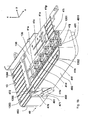
- FIG. 1a is a perspective view of a pressure device for flat goods to a transport module shown from the top front and right.
- a - not shown - postal item or flat good can be supplied above a feed table 13.
- the aforementioned transport module has been arranged above the feed table 13 but has not been shown.
- the transport module has, in a manner known per se, a conveyor belt for the transport of postal items or flat goods.
- the pressure device 40 is disposed below the feed table 13 and acts through a large rectangular opening 130 of the feed table 13 in the z direction on the underside of the supplied mail piece or flat goods.
- the spring elements 41 a to 41 j are shown in the operating position and not lowered. The lowering is intended to eliminate a jam on mailpieces or flat goods.
- the feed table 13 has on the input current side in the feed region slide rails 136, which are integrally formed on a base plate 135 and reduce the sliding friction for supplied flat goods. Between the feed area and the rectangular opening 130, a ramp 137 is arranged, which raises the front edge of the supplied flat goods. It forms together with a - not shown - a sluice plate, wherein the plate is arranged parallel to the base plate 135 above the same and serves as an upper guide for flat goods. Thus, flat goods can be inserted only up to a certain thickness.
- a guide wall 139 extending in the transport direction and extending orthogonally into the height (z-direction) is formed on the base plate 135, which is widened in the inlet region 138 for flat goods or mail pieces. The latter are detected after exceeding the ramp 137 by means of sensors.
- holes 1301, 1302 and 1303 are formed, which are provided for the transmitting diodes of the sensors.
- the transmitting diodes and phototransistors or diodes are part of transmitted light barriers.
- the base plate 135 is disposed in the mail transport direction x after the ramp 137 and has a middle sized first port 131 and a middle second port 132 opposite the ink jet printheads, the first port 131 being compared to the second port 132 in the y direction, i. is arranged offset by a first distance A in the transverse direction to the mail piece transport direction.
- the first distance A is slightly less than the entire printhead length of a 1 ⁇ 2 "HP print head
- the second aperture 132 is offset from the first aperture 131 in the x-direction, ie offset in the mailpiece transport direction by a second distance B which is more than one whole
- Both the first and second openings 131 and 132 in the feed table 13 are formed in a ⁇ -shape (phi-shaped) .
- the two first and second openings 131 and 132 are respectively preceded by an elongate rectangular opening 133, 134 upstream of the post.
- the area of the large rectangular third opening 130 exceeds the area of the middle sized second opening 132 by more than an order of magnitude with the second opening 132 offset in the y direction from the third opening 130, the offset being so minimal that both openings are immediately adjacent each other are adjacent or separated only by a very thin connecting web.
- the third opening 130 allows a passage of spring elements 41 a to 41 j of the resiliently against a flat Good or mailpiece pushing pressure device 40 which is disposed below the feed table 13.
- the feed table 13 is mounted on a housing lower shell 49.
- the housing lower shell 49 has a right side wall 491, a front wall 492 and a left side wall 493 and a base 496.
- the right side wall 491 has a recess 4911 on the upper edge for spring elements 41i and 41j, which can be lowered post downstream.
- the feed table 13 is stepped downwardly on the downstream frame 1351 such that the frame 1351 defines the third opening 130 and into the recess 4911 on the upper edge of the right Side wall 491 fits.
- the right side wall 491 is formed opposite to a right base side wall 4961 offset in the transport direction. At the same offset the base front wall 4962 is formed offset relative to the front wall 492 in the y-direction.
- the front wall 492 has a recess 47 in which the wall is set back to the pedestal front wall 4962.
- an actuating element 46 is arranged, whose surface terminates with the running surface of the feed table.
- FIG. 1b is a perspective view of a pressure device for flat goods to a transport module from the top front and right with lowered spring elements shown.
- the spring elements 41 a to 41 j in the third opening 130 of the feed table 13 are drawn lowered in the transport direction (x-direction) and in the direction of gravity (counter to the z-direction) and lie below the feed table.
- the frame 1351 in the recess 4911 on the upper edge of the right side wall 491 is therefore stepped down.
- the feed table 13 is mounted on the housing lower shell 49 via screws 1352, 1353 and 1354 in the base plate 135 by means of screws (not shown).
- the hole 1354 is near the left side wall 493, and the holes 1352 and 1353 are disposed near the front wall 492 on the feed table 13.
- the base plate 135 of the feed table 13 has a fourth opening 1355 on the front wall 492 which allows operation of the actuator whose surface 460 in structure is equal to that of the surface of the feed table 13.
- the actuator has a power arm 461 which exits an opening 470 of the left side wall 471 of the indentation.
- the pressing device 40 will be explained in detail below.
- FIG. 1c is a perspective view of a pressure device for flat goods to a transport module from the top rear and right with lowered spring elements and with open-topped housing shown.
- the pressure device 40 can be adjusted by a slider 42 from the operating position to the second position shown.
- the spring elements 41 a to 41 j are arranged in two rows on both sides of the slider 42 and anchored on the housing lower shell 49.
- the spring element 41a for anchoring a foot 415a which closes a bearing opening 4971 on an angled upper edge of a first inner wall 497 of the housing lower shell 49 on one side.
- the housing lower shell 49 is parallel to a second inner wall 498, which is constructed symmetrically to the first, both having angled upper edges 4972, 4982, which face each other.
- the housing lower shell 49 has a bottom plate 490, on which both the first and second inner walls are standing and the base are formed.
- the pedestal has a left pedestal sidewall 4963 which merges with a pedestal step 495 in the left sidewall 493.
- the left side wall 493 has on its inner sides a hook 494 for attachment of a - not shown - tension spring.
- On the base stage 495 are mounting columns 4931 and 4932, which lean against the left side wall 493.
- On the inside of the transition of the front wall 492 to the right side wall 491 stands on a pedestal stage another mounting column 4921.
- the mounting column serve to attach the feed table.
- the feed table and the tension spring were removed from the drawing Fig. 1c omitted to increase their clarity.
- the pedestal has a right pedestal sidewall 4961 which merges with pedestal 495 into right sidewall 491.
- the housing lower shell 49 has a first number of such guide receptacles, which are integrally formed on the angled upper edges 4972, 4982.
- the slider 42 has at its lower edge an equal number of guide leaves 44, which are distributed symmetrically on both sides.
- the slider 42 has at its Upper edge of a second number of fingers 43a to 43j are distributed symmetrically on both sides, wherein the second number corresponds to the number of spring elements used 41 a to 41 j.
- the indentation on the front wall 492 has an indentation wall 472 parallel to the front wall 492, a right indentation sidewall 473 and a left indentation sidewall 473 with an opening 470 from which the force arm 461 of an angled lever, which is used here as an actuator, surrounds the slider 42 to move against a spring action.
- an actuating force is exerted, which is transmitted via the angled part of arm 462 of the angle lever according to the law of levers on the angled load arm 463.
- the angle lever rotates about an axis which passes through a shaft 464, which is rotatably mounted in the bearing openings 4971, 4981 of the two inner walls of the housing lower shell 49.
- a bolt carrier 465 is integrally formed with a bolt 4651 which slides in a slot 421 which is disposed at the one end of the slider 42 at its upper edge.
- a pin 424 for attachment of the tension spring - not shown - attached is integrally formed with a bolt carrier 465.
- FIG. 1d is a perspective view of a pressure device for flat goods to a transport module from the top rear and right with lowered spring elements without housing shown.
- the spring elements 41a to 41j are drawn by the fingers 43a to 43j of the slider 42 in a second position, which differs from the operating position.
- FIG. 2 a rear view of the slide of the pressure device with lowered spring elements and mounted lever.
- the slider 42 acts in an x / z plane.
- the spring elements 41a to 41j are lowered by the fingers 43a to 43j of the slider 42 in the direction of the white arrow when the shaft 464 of the angle lever in Direction of the black arrow is turned.
- the bolt 4651 of the load arm 463 is movably disposed in the slot 421. A rotation of the angle lever upon actuation of the actuating element 46 causes a force of the load arm 463, which is transmitted via the bolt 4651 on the slot 421.
- the slider 42 is proportionately moved in the x direction against the force of the tension spring 45, wherein the attached to the lower housing shell 49 tension spring 45 is brought to a pin 424 of the slider 42 into engagement.
- the slider 42 is also against the z-direction, ie moved in the direction of gravity.
- FIG. 3 is a front view of a slider 42 of the pressure device shown.
- FIG. 4 is a front view of a slider of the pressure device shown with lowered spring elements and mounted lever.
- the movement of the actuating element (angle lever) 46 is converted via a arranged at the end of the slider 42 slot 421 in guided by guide blades 44 movement of the slider whose fingers push 43b ... 43j on the spring elements 41 b to 41 j and this down lower.
- FIG. 5 is a perspective view of a spring element of the pressure device shown.
- Each spring element 41 is made of spring steel sheet and has a foot 415, which is designed for anchoring and a head 411-413, 416, which is equipped with a means for reducing the friction.
- the latter may for example consist of a roller 417 which is rotatably mounted in a head-mounted holder 416.
- the spring steel sheet extending from head to foot may be Z- or S-shaped.
- the first region 411 has a first opening 4111 which extends into the second region 412 and is angled from the second region 412. The first opening is provided for the roller 417.
- the first region 411 has a second opening 4112 at the end of the spring steel sheet for mounting the support 416, the support 416 extending via second and third regions 412 and 413 to the beginning of the fourth region 414 of the spring steel sheet.
- a hole for a fastening bolt, rivet or screw 4161 for fixing the bracket 416 is provided.
- the attachment can also be done by alternative means.
- the device for pressing flat goods to a transport module may alternatively consist of a plurality of pressure elements whose number is substantially higher than that shown in the illustrated embodiment.
- each pressure element can also consist of an S-shaped bent spring steel sheet or of another artificial material having a spring characteristic. Such a material should have in the head area a sufficiently smooth surface or a sliding friction-reducing structure.
Landscapes
- Sorting Of Articles (AREA)
- Feeding Of Articles By Means Other Than Belts Or Rollers (AREA)
- Reciprocating Conveyors (AREA)
- Sheets, Magazines, And Separation Thereof (AREA)
Applications Claiming Priority (1)
| Application Number | Priority Date | Filing Date | Title |
|---|---|---|---|
| DE102007060734.4A DE102007060734B4 (de) | 2007-12-17 | 2007-12-17 | Vorrichtung zum Andrücken flacher Güter an ein Transportmodul |
Publications (3)
| Publication Number | Publication Date |
|---|---|
| EP2072271A2 true EP2072271A2 (fr) | 2009-06-24 |
| EP2072271A3 EP2072271A3 (fr) | 2010-09-29 |
| EP2072271B1 EP2072271B1 (fr) | 2018-06-13 |
Family
ID=40566285
Family Applications (1)
| Application Number | Title | Priority Date | Filing Date |
|---|---|---|---|
| EP08018403.9A Not-in-force EP2072271B1 (fr) | 2007-12-17 | 2008-10-21 | Dispositif d'application d'une pression sur des marchandises plates sur un module de transport |
Country Status (3)
| Country | Link |
|---|---|
| US (1) | US7810810B2 (fr) |
| EP (1) | EP2072271B1 (fr) |
| DE (1) | DE102007060734B4 (fr) |
Cited By (2)
| Publication number | Priority date | Publication date | Assignee | Title |
|---|---|---|---|---|
| DE202010015351U1 (de) | 2010-11-11 | 2011-02-03 | Francotyp-Postalia Gmbh | Vorrichtung zur Absenkung, Positionierung und Anhebung von Druckelementen eines Druckergeräts |
| DE202010015354U1 (de) | 2010-11-11 | 2011-02-10 | Francotyp-Postalia Gmbh | Modular aufgebautes Druckergerät mit einer entnehmbaren kastenförmigen Baueinheit |
Families Citing this family (5)
| Publication number | Priority date | Publication date | Assignee | Title |
|---|---|---|---|---|
| EP2688047B1 (fr) | 2012-07-18 | 2015-05-06 | Francotyp-Postalia GmbH | Appareil d'impression |
| US9010755B2 (en) | 2012-07-18 | 2015-04-21 | Francotyp-Postalia Gmbh | Printer apparatus |
| DE202013005632U1 (de) | 2013-06-21 | 2013-07-04 | Francotyp-Postalia Gmbh | Druckergerät |
| DE202013105555U1 (de) * | 2013-12-06 | 2014-01-13 | Francotyp-Postalia Gmbh | Druckergerät |
| CN118561061B (zh) * | 2024-08-02 | 2024-10-18 | 滁州天源纸业有限公司 | 一种纸板输送装置 |
Citations (12)
| Publication number | Priority date | Publication date | Assignee | Title |
|---|---|---|---|---|
| DD233101B5 (de) | 1983-07-23 | 1995-10-19 | Francotyp Postalia Gmbh | Postfrankiermaschine |
| US5467709A (en) | 1994-12-22 | 1995-11-21 | Pitney Bowes Inc. | Mailing machine utilizing ink jet printer |
| DE19605015C1 (de) | 1996-01-31 | 1997-03-06 | Francotyp Postalia Gmbh | Vorrichtung zum Bedrucken eines auf einer Kante stehenden Druckträgers |
| DE19605014C1 (de) | 1996-01-31 | 1997-03-13 | Francotyp Postalia Gmbh | Vorrichtung zum Bedrucken eines auf einer Kante stehenden Druckträgers |
| US5813326A (en) | 1994-12-22 | 1998-09-29 | Pitney Bowes Inc. | Mailing machine utilizing ink jet printer |
| WO1999044174A1 (fr) | 1998-02-25 | 1999-09-02 | Secap | Dispositif d'affranchissement et d'adressage |
| US5949444A (en) | 1996-01-31 | 1999-09-07 | Francotyp Postalia Ag & Co. | Device for printing stock |
| US6550994B2 (en) | 2001-07-20 | 2003-04-22 | Pitney Bowes Inc. | System for printing information on a mailing medium |
| US6585433B2 (en) | 2001-03-09 | 2003-07-01 | Pitney Bowes Inc. | Print signal generation |
| EP1170141B1 (fr) | 2000-07-06 | 2004-04-14 | Francotyp-Postalia AG & Co. KG | Dispositif pour imprimer sur un support d'impression |
| US6776089B2 (en) | 2002-01-11 | 2004-08-17 | Canon Kabushiki Kaisha | Screen printer |
| EP1079975B1 (fr) | 1999-03-16 | 2006-11-29 | SECAP (Groupe Pitney Bowes) | Dispositif pour imprimer un signe et machine a affranchir le comportant |
Family Cites Families (17)
| Publication number | Priority date | Publication date | Assignee | Title |
|---|---|---|---|---|
| US3748442A (en) * | 1972-02-11 | 1973-07-24 | Amp Inc | Card reader transport device |
| DE2327932A1 (de) * | 1973-06-01 | 1974-12-19 | Licentia Gmbh | Foerdereinrichtung |
| US3924847A (en) * | 1973-10-11 | 1975-12-09 | Umc Ind | Anti-retrieval device |
| US4903954A (en) * | 1987-12-02 | 1990-02-27 | Pitney Bowes Inc. | Sheet transporting apparatus |
| US5011129A (en) * | 1989-11-14 | 1991-04-30 | Pitney Bowes Inc. | Jam clearance apparatus for sheetfeeding device |
| US5121916A (en) * | 1991-03-06 | 1992-06-16 | Pitney Bowes Inc. | Article of manufacture for use in letter processing apparatus |
| US5575465A (en) * | 1994-12-20 | 1996-11-19 | Pitney Bowes Inc. | Apparatus for transporting documents conveyed from two directions |
| FR2742693B1 (fr) * | 1995-12-20 | 1998-03-13 | Neopost Ind | Dispositif pour le transport et le guidage d'articles de courrier |
| DE19645303C1 (de) * | 1996-01-31 | 1997-12-11 | Francotyp Postalia Gmbh | Vorrichtung zum Bedrucken eines auf einer Kante stehenden Druckträgers |
| DE19912807A1 (de) * | 1999-03-13 | 2000-09-21 | Francotyp Postalia Gmbh | Anordnung zur Dimensionsbestimmung von Druckträgern |
| FR2797219B1 (fr) * | 1999-08-03 | 2002-03-29 | Neopost Ind | Dispositif de debourrage pour alimenteur de machine a affranchir |
| US6557850B1 (en) * | 2001-11-16 | 2003-05-06 | Ncr Corporation | Retractable track guide apparatus for use in a document processing system |
| CN1206113C (zh) * | 2002-04-17 | 2005-06-15 | 株式会社理光 | 纸输送装置及设有该纸输送装置的图像形成装置 |
| US6820873B2 (en) * | 2003-03-06 | 2004-11-23 | Pitney Bowes Inc. | Transport mechanism for a mailing machine |
| US7195337B2 (en) * | 2004-01-05 | 2007-03-27 | Pitney Bowes Inc. | Postage meter print head and carriage |
| US20060220294A1 (en) * | 2005-03-21 | 2006-10-05 | Pitney Bowes Incorporated | Jam release mechanism for a mailing machine |
| US7464931B2 (en) * | 2005-03-31 | 2008-12-16 | Heidelberger Druckmaschinen Ag | Apparatus for positioning a trailing edge of sheets |
-
2007
- 2007-12-17 DE DE102007060734.4A patent/DE102007060734B4/de not_active Expired - Fee Related
-
2008
- 2008-10-21 EP EP08018403.9A patent/EP2072271B1/fr not_active Not-in-force
- 2008-10-24 US US12/257,918 patent/US7810810B2/en not_active Expired - Fee Related
Patent Citations (12)
| Publication number | Priority date | Publication date | Assignee | Title |
|---|---|---|---|---|
| DD233101B5 (de) | 1983-07-23 | 1995-10-19 | Francotyp Postalia Gmbh | Postfrankiermaschine |
| US5467709A (en) | 1994-12-22 | 1995-11-21 | Pitney Bowes Inc. | Mailing machine utilizing ink jet printer |
| US5813326A (en) | 1994-12-22 | 1998-09-29 | Pitney Bowes Inc. | Mailing machine utilizing ink jet printer |
| DE19605015C1 (de) | 1996-01-31 | 1997-03-06 | Francotyp Postalia Gmbh | Vorrichtung zum Bedrucken eines auf einer Kante stehenden Druckträgers |
| DE19605014C1 (de) | 1996-01-31 | 1997-03-13 | Francotyp Postalia Gmbh | Vorrichtung zum Bedrucken eines auf einer Kante stehenden Druckträgers |
| US5949444A (en) | 1996-01-31 | 1999-09-07 | Francotyp Postalia Ag & Co. | Device for printing stock |
| WO1999044174A1 (fr) | 1998-02-25 | 1999-09-02 | Secap | Dispositif d'affranchissement et d'adressage |
| EP1079975B1 (fr) | 1999-03-16 | 2006-11-29 | SECAP (Groupe Pitney Bowes) | Dispositif pour imprimer un signe et machine a affranchir le comportant |
| EP1170141B1 (fr) | 2000-07-06 | 2004-04-14 | Francotyp-Postalia AG & Co. KG | Dispositif pour imprimer sur un support d'impression |
| US6585433B2 (en) | 2001-03-09 | 2003-07-01 | Pitney Bowes Inc. | Print signal generation |
| US6550994B2 (en) | 2001-07-20 | 2003-04-22 | Pitney Bowes Inc. | System for printing information on a mailing medium |
| US6776089B2 (en) | 2002-01-11 | 2004-08-17 | Canon Kabushiki Kaisha | Screen printer |
Cited By (4)
| Publication number | Priority date | Publication date | Assignee | Title |
|---|---|---|---|---|
| DE202010015351U1 (de) | 2010-11-11 | 2011-02-03 | Francotyp-Postalia Gmbh | Vorrichtung zur Absenkung, Positionierung und Anhebung von Druckelementen eines Druckergeräts |
| DE202010015354U1 (de) | 2010-11-11 | 2011-02-10 | Francotyp-Postalia Gmbh | Modular aufgebautes Druckergerät mit einer entnehmbaren kastenförmigen Baueinheit |
| EP2452822A1 (fr) | 2010-11-11 | 2012-05-16 | Francotyp-Postalia GmbH | Dispositif d'abaissement, de positionnement et de levage d'éléments de pression d'un appareil d'impression |
| EP2452824A1 (fr) | 2010-11-11 | 2012-05-16 | Francotyp-Postalia GmbH | Appareil d'impression monté de manière modulaire et doté d'un composant en forme de caisse amovible |
Also Published As
| Publication number | Publication date |
|---|---|
| EP2072271B1 (fr) | 2018-06-13 |
| DE102007060734B4 (de) | 2017-05-04 |
| DE102007060734A1 (de) | 2009-06-18 |
| EP2072271A3 (fr) | 2010-09-29 |
| US20090152802A1 (en) | 2009-06-18 |
| US7810810B2 (en) | 2010-10-12 |
Similar Documents
| Publication | Publication Date | Title |
|---|---|---|
| EP2072271B1 (fr) | Dispositif d'application d'une pression sur des marchandises plates sur un module de transport | |
| DE69530664T2 (de) | Frankiermaschine mit Tintenstrahldrucker | |
| EP0520001B1 (fr) | Imprimante avec logement subdivise sur le plan du support d'impression | |
| DE4330798C2 (de) | Drucker | |
| DE19645303C1 (de) | Vorrichtung zum Bedrucken eines auf einer Kante stehenden Druckträgers | |
| DE69810402T2 (de) | Drucker und Verfahren zum Schneiden von Aufzeichnungsträgern | |
| DE3734268A1 (de) | Vorrichtung zum ausrichten von briefumschlaegen in einer frankiermaschine | |
| EP2073173B1 (fr) | Dispositif destiné à changer des cartouches d'encre | |
| EP0969969A1 (fr) | Imprimante servant a imprimer des feuilles individuelles et des bandes de papier sans fin | |
| EP1170141B1 (fr) | Dispositif pour imprimer sur un support d'impression | |
| EP0587531B1 (fr) | Procédé et dispositif pour alimentes des feuilles à une machine à plier avec une orientation correcte | |
| DE69816717T2 (de) | Weichenvorrichtung in einem Förderer für plattenförmige Gegenstände | |
| AT501863B1 (de) | Haltevorrichtung für tintenstrahldrucker | |
| EP2072268A2 (fr) | Dispositif d'application d'une pression sur des marchandises plates sur un module de transport | |
| EP1782954A1 (fr) | Dispositif pour le nettoyage d'une tête à jet d'encre | |
| DE3332992A1 (de) | Drucker mit mosaikdruckkoepfen | |
| EP2072267B1 (fr) | Dispositif de transport pour des produits plats à imprimer | |
| EP2072263B1 (fr) | Combinaison d'une tête d'impression à jet d'encre et d'un dispositif destiné à l'éjection dégorgeante d'une tête d'impression à jet d'encre | |
| EP0961236B1 (fr) | Dispositif d'impression de courrier | |
| EP0585676A2 (fr) | Machine d'affranchissement | |
| DE29601452U1 (de) | Stapelvorrichtung für kartenförmige Güter | |
| EP2902974B1 (fr) | Imprimante | |
| DE2635006B2 (de) | Vorrichtung zur automatischen Abstandsregelung zwischen einem Druckkopf und einem zu bedruckenden Informationsträger | |
| DE4309593C2 (de) | Anordnung zur Führung eines Aufzeichnungsträgers | |
| CH619891A5 (en) | Apparatus for printing on strip material, in particular label strips |
Legal Events
| Date | Code | Title | Description |
|---|---|---|---|
| PUAI | Public reference made under article 153(3) epc to a published international application that has entered the european phase |
Free format text: ORIGINAL CODE: 0009012 |
|
| AK | Designated contracting states |
Kind code of ref document: A2 Designated state(s): AT BE BG CH CY CZ DE DK EE ES FI FR GB GR HR HU IE IS IT LI LT LU LV MC MT NL NO PL PT RO SE SI SK TR |
|
| AX | Request for extension of the european patent |
Extension state: AL BA MK RS |
|
| PUAL | Search report despatched |
Free format text: ORIGINAL CODE: 0009013 |
|
| AK | Designated contracting states |
Kind code of ref document: A3 Designated state(s): AT BE BG CH CY CZ DE DK EE ES FI FR GB GR HR HU IE IS IT LI LT LU LV MC MT NL NO PL PT RO SE SI SK TR |
|
| AX | Request for extension of the european patent |
Extension state: AL BA MK RS |
|
| 17P | Request for examination filed |
Effective date: 20110201 |
|
| AKX | Designation fees paid |
Designated state(s): AT BE BG CH CY CZ DE DK EE ES FI FR GB GR HR HU IE IS IT LI LT LU LV MC MT NL NO PL PT RO SE SI SK TR |
|
| RAP1 | Party data changed (applicant data changed or rights of an application transferred) |
Owner name: FRANCOTYP-POSTALIA GMBH |
|
| 17Q | First examination report despatched |
Effective date: 20170714 |
|
| GRAP | Despatch of communication of intention to grant a patent |
Free format text: ORIGINAL CODE: EPIDOSNIGR1 |
|
| INTG | Intention to grant announced |
Effective date: 20180126 |
|
| GRAS | Grant fee paid |
Free format text: ORIGINAL CODE: EPIDOSNIGR3 |
|
| GRAA | (expected) grant |
Free format text: ORIGINAL CODE: 0009210 |
|
| AK | Designated contracting states |
Kind code of ref document: B1 Designated state(s): AT BE BG CH CY CZ DE DK EE ES FI FR GB GR HR HU IE IS IT LI LT LU LV MC MT NL NO PL PT RO SE SI SK TR |
|
| REG | Reference to a national code |
Ref country code: GB Ref legal event code: FG4D Free format text: NOT ENGLISH |
|
| REG | Reference to a national code |
Ref country code: CH Ref legal event code: EP Ref country code: AT Ref legal event code: REF Ref document number: 1008072 Country of ref document: AT Kind code of ref document: T Effective date: 20180615 |
|
| REG | Reference to a national code |
Ref country code: IE Ref legal event code: FG4D Free format text: LANGUAGE OF EP DOCUMENT: GERMAN |
|
| REG | Reference to a national code |
Ref country code: DE Ref legal event code: R096 Ref document number: 502008016123 Country of ref document: DE |
|
| REG | Reference to a national code |
Ref country code: NL Ref legal event code: MP Effective date: 20180613 |
|
| REG | Reference to a national code |
Ref country code: LT Ref legal event code: MG4D |
|
| PG25 | Lapsed in a contracting state [announced via postgrant information from national office to epo] |
Ref country code: ES Free format text: LAPSE BECAUSE OF FAILURE TO SUBMIT A TRANSLATION OF THE DESCRIPTION OR TO PAY THE FEE WITHIN THE PRESCRIBED TIME-LIMIT Effective date: 20180613 Ref country code: CY Free format text: LAPSE BECAUSE OF FAILURE TO SUBMIT A TRANSLATION OF THE DESCRIPTION OR TO PAY THE FEE WITHIN THE PRESCRIBED TIME-LIMIT Effective date: 20180613 Ref country code: FI Free format text: LAPSE BECAUSE OF FAILURE TO SUBMIT A TRANSLATION OF THE DESCRIPTION OR TO PAY THE FEE WITHIN THE PRESCRIBED TIME-LIMIT Effective date: 20180613 Ref country code: LT Free format text: LAPSE BECAUSE OF FAILURE TO SUBMIT A TRANSLATION OF THE DESCRIPTION OR TO PAY THE FEE WITHIN THE PRESCRIBED TIME-LIMIT Effective date: 20180613 Ref country code: BG Free format text: LAPSE BECAUSE OF FAILURE TO SUBMIT A TRANSLATION OF THE DESCRIPTION OR TO PAY THE FEE WITHIN THE PRESCRIBED TIME-LIMIT Effective date: 20180913 Ref country code: SE Free format text: LAPSE BECAUSE OF FAILURE TO SUBMIT A TRANSLATION OF THE DESCRIPTION OR TO PAY THE FEE WITHIN THE PRESCRIBED TIME-LIMIT Effective date: 20180613 Ref country code: NO Free format text: LAPSE BECAUSE OF FAILURE TO SUBMIT A TRANSLATION OF THE DESCRIPTION OR TO PAY THE FEE WITHIN THE PRESCRIBED TIME-LIMIT Effective date: 20180913 |
|
| PG25 | Lapsed in a contracting state [announced via postgrant information from national office to epo] |
Ref country code: GR Free format text: LAPSE BECAUSE OF FAILURE TO SUBMIT A TRANSLATION OF THE DESCRIPTION OR TO PAY THE FEE WITHIN THE PRESCRIBED TIME-LIMIT Effective date: 20180914 Ref country code: HR Free format text: LAPSE BECAUSE OF FAILURE TO SUBMIT A TRANSLATION OF THE DESCRIPTION OR TO PAY THE FEE WITHIN THE PRESCRIBED TIME-LIMIT Effective date: 20180613 Ref country code: LV Free format text: LAPSE BECAUSE OF FAILURE TO SUBMIT A TRANSLATION OF THE DESCRIPTION OR TO PAY THE FEE WITHIN THE PRESCRIBED TIME-LIMIT Effective date: 20180613 |
|
| PG25 | Lapsed in a contracting state [announced via postgrant information from national office to epo] |
Ref country code: NL Free format text: LAPSE BECAUSE OF FAILURE TO SUBMIT A TRANSLATION OF THE DESCRIPTION OR TO PAY THE FEE WITHIN THE PRESCRIBED TIME-LIMIT Effective date: 20180613 |
|
| PG25 | Lapsed in a contracting state [announced via postgrant information from national office to epo] |
Ref country code: SK Free format text: LAPSE BECAUSE OF FAILURE TO SUBMIT A TRANSLATION OF THE DESCRIPTION OR TO PAY THE FEE WITHIN THE PRESCRIBED TIME-LIMIT Effective date: 20180613 Ref country code: RO Free format text: LAPSE BECAUSE OF FAILURE TO SUBMIT A TRANSLATION OF THE DESCRIPTION OR TO PAY THE FEE WITHIN THE PRESCRIBED TIME-LIMIT Effective date: 20180613 Ref country code: CZ Free format text: LAPSE BECAUSE OF FAILURE TO SUBMIT A TRANSLATION OF THE DESCRIPTION OR TO PAY THE FEE WITHIN THE PRESCRIBED TIME-LIMIT Effective date: 20180613 Ref country code: PL Free format text: LAPSE BECAUSE OF FAILURE TO SUBMIT A TRANSLATION OF THE DESCRIPTION OR TO PAY THE FEE WITHIN THE PRESCRIBED TIME-LIMIT Effective date: 20180613 Ref country code: EE Free format text: LAPSE BECAUSE OF FAILURE TO SUBMIT A TRANSLATION OF THE DESCRIPTION OR TO PAY THE FEE WITHIN THE PRESCRIBED TIME-LIMIT Effective date: 20180613 Ref country code: IS Free format text: LAPSE BECAUSE OF FAILURE TO SUBMIT A TRANSLATION OF THE DESCRIPTION OR TO PAY THE FEE WITHIN THE PRESCRIBED TIME-LIMIT Effective date: 20181013 |
|
| PG25 | Lapsed in a contracting state [announced via postgrant information from national office to epo] |
Ref country code: IT Free format text: LAPSE BECAUSE OF FAILURE TO SUBMIT A TRANSLATION OF THE DESCRIPTION OR TO PAY THE FEE WITHIN THE PRESCRIBED TIME-LIMIT Effective date: 20180613 |
|
| REG | Reference to a national code |
Ref country code: DE Ref legal event code: R097 Ref document number: 502008016123 Country of ref document: DE |
|
| PLBE | No opposition filed within time limit |
Free format text: ORIGINAL CODE: 0009261 |
|
| STAA | Information on the status of an ep patent application or granted ep patent |
Free format text: STATUS: NO OPPOSITION FILED WITHIN TIME LIMIT |
|
| REG | Reference to a national code |
Ref country code: DE Ref legal event code: R119 Ref document number: 502008016123 Country of ref document: DE |
|
| 26N | No opposition filed |
Effective date: 20190314 |
|
| PG25 | Lapsed in a contracting state [announced via postgrant information from national office to epo] |
Ref country code: DK Free format text: LAPSE BECAUSE OF FAILURE TO SUBMIT A TRANSLATION OF THE DESCRIPTION OR TO PAY THE FEE WITHIN THE PRESCRIBED TIME-LIMIT Effective date: 20180613 Ref country code: SI Free format text: LAPSE BECAUSE OF FAILURE TO SUBMIT A TRANSLATION OF THE DESCRIPTION OR TO PAY THE FEE WITHIN THE PRESCRIBED TIME-LIMIT Effective date: 20180613 |
|
| REG | Reference to a national code |
Ref country code: CH Ref legal event code: PL |
|
| GBPC | Gb: european patent ceased through non-payment of renewal fee |
Effective date: 20181021 |
|
| REG | Reference to a national code |
Ref country code: BE Ref legal event code: MM Effective date: 20181031 |
|
| PG25 | Lapsed in a contracting state [announced via postgrant information from national office to epo] |
Ref country code: LU Free format text: LAPSE BECAUSE OF NON-PAYMENT OF DUE FEES Effective date: 20181021 Ref country code: MC Free format text: LAPSE BECAUSE OF FAILURE TO SUBMIT A TRANSLATION OF THE DESCRIPTION OR TO PAY THE FEE WITHIN THE PRESCRIBED TIME-LIMIT Effective date: 20180613 |
|
| REG | Reference to a national code |
Ref country code: IE Ref legal event code: MM4A |
|
| PG25 | Lapsed in a contracting state [announced via postgrant information from national office to epo] |
Ref country code: DE Free format text: LAPSE BECAUSE OF NON-PAYMENT OF DUE FEES Effective date: 20190501 |
|
| PG25 | Lapsed in a contracting state [announced via postgrant information from national office to epo] |
Ref country code: FR Free format text: LAPSE BECAUSE OF NON-PAYMENT OF DUE FEES Effective date: 20181031 Ref country code: BE Free format text: LAPSE BECAUSE OF NON-PAYMENT OF DUE FEES Effective date: 20181031 Ref country code: CH Free format text: LAPSE BECAUSE OF NON-PAYMENT OF DUE FEES Effective date: 20181031 Ref country code: LI Free format text: LAPSE BECAUSE OF NON-PAYMENT OF DUE FEES Effective date: 20181031 |
|
| PG25 | Lapsed in a contracting state [announced via postgrant information from national office to epo] |
Ref country code: GB Free format text: LAPSE BECAUSE OF NON-PAYMENT OF DUE FEES Effective date: 20181021 Ref country code: IE Free format text: LAPSE BECAUSE OF NON-PAYMENT OF DUE FEES Effective date: 20181021 |
|
| REG | Reference to a national code |
Ref country code: AT Ref legal event code: MM01 Ref document number: 1008072 Country of ref document: AT Kind code of ref document: T Effective date: 20181021 |
|
| PG25 | Lapsed in a contracting state [announced via postgrant information from national office to epo] |
Ref country code: MT Free format text: LAPSE BECAUSE OF FAILURE TO SUBMIT A TRANSLATION OF THE DESCRIPTION OR TO PAY THE FEE WITHIN THE PRESCRIBED TIME-LIMIT Effective date: 20180613 Ref country code: AT Free format text: LAPSE BECAUSE OF NON-PAYMENT OF DUE FEES Effective date: 20181021 |
|
| PG25 | Lapsed in a contracting state [announced via postgrant information from national office to epo] |
Ref country code: TR Free format text: LAPSE BECAUSE OF FAILURE TO SUBMIT A TRANSLATION OF THE DESCRIPTION OR TO PAY THE FEE WITHIN THE PRESCRIBED TIME-LIMIT Effective date: 20180613 |
|
| PG25 | Lapsed in a contracting state [announced via postgrant information from national office to epo] |
Ref country code: PT Free format text: LAPSE BECAUSE OF FAILURE TO SUBMIT A TRANSLATION OF THE DESCRIPTION OR TO PAY THE FEE WITHIN THE PRESCRIBED TIME-LIMIT Effective date: 20180613 |
|
| PG25 | Lapsed in a contracting state [announced via postgrant information from national office to epo] |
Ref country code: HU Free format text: LAPSE BECAUSE OF FAILURE TO SUBMIT A TRANSLATION OF THE DESCRIPTION OR TO PAY THE FEE WITHIN THE PRESCRIBED TIME-LIMIT; INVALID AB INITIO Effective date: 20081021 |