EP2072358B1 - Palier d'essuie-glace - Google Patents
Palier d'essuie-glace Download PDFInfo
- Publication number
- EP2072358B1 EP2072358B1 EP20080105631 EP08105631A EP2072358B1 EP 2072358 B1 EP2072358 B1 EP 2072358B1 EP 20080105631 EP20080105631 EP 20080105631 EP 08105631 A EP08105631 A EP 08105631A EP 2072358 B1 EP2072358 B1 EP 2072358B1
- Authority
- EP
- European Patent Office
- Prior art keywords
- bearing
- bearing shaft
- shaft
- section
- securing means
- Prior art date
- Legal status (The legal status is an assumption and is not a legal conclusion. Google has not performed a legal analysis and makes no representation as to the accuracy of the status listed.)
- Ceased
Links
Images


Classifications
-
- B—PERFORMING OPERATIONS; TRANSPORTING
- B60—VEHICLES IN GENERAL
- B60S—SERVICING, CLEANING, REPAIRING, SUPPORTING, LIFTING, OR MANOEUVRING OF VEHICLES, NOT OTHERWISE PROVIDED FOR
- B60S1/00—Cleaning of vehicles
- B60S1/02—Cleaning windscreens, windows or optical devices
- B60S1/04—Wipers or the like, e.g. scrapers
- B60S1/06—Wipers or the like, e.g. scrapers characterised by the drive
- B60S1/16—Means for transmitting drive
- B60S1/18—Means for transmitting drive mechanically
- B60S1/24—Means for transmitting drive mechanically by rotary cranks
-
- B—PERFORMING OPERATIONS; TRANSPORTING
- B60—VEHICLES IN GENERAL
- B60S—SERVICING, CLEANING, REPAIRING, SUPPORTING, LIFTING, OR MANOEUVRING OF VEHICLES, NOT OTHERWISE PROVIDED FOR
- B60S1/00—Cleaning of vehicles
- B60S1/02—Cleaning windscreens, windows or optical devices
- B60S1/04—Wipers or the like, e.g. scrapers
- B60S1/0488—Wiper arrangement for crash protection or impact absorption
-
- B—PERFORMING OPERATIONS; TRANSPORTING
- B60—VEHICLES IN GENERAL
- B60S—SERVICING, CLEANING, REPAIRING, SUPPORTING, LIFTING, OR MANOEUVRING OF VEHICLES, NOT OTHERWISE PROVIDED FOR
- B60S1/00—Cleaning of vehicles
- B60S1/02—Cleaning windscreens, windows or optical devices
- B60S1/04—Wipers or the like, e.g. scrapers
- B60S1/32—Wipers or the like, e.g. scrapers characterised by constructional features of wiper blade arms or blades
- B60S1/34—Wiper arms; Mountings therefor
- B60S1/3488—Means for mounting wiper arms onto the vehicle
- B60S1/3495—Means for mounting the drive mechanism to the wiper shaft
Definitions
- the invention relates to a wiper bearing according to the preamble of claim 1 and to an assembly method for a wiper bearing according to the preamble of claim 7.
- a wiper bearing with the features of the preamble of claim 1 is known from US 6,845,540 B1 known.
- the invention has for its object to provide a wiper bearing with overhead bearing plate, which is designed such that the danger of injury emanating from it is minimized in the event of a crash. Furthermore, the object is to propose an assembly method for such a wiper bearing.
- the invention is based on the idea to secure the non-rotatably connected to the bearing plate, a mounting portion for fixing a wiper arm having upper portion of the bearing shaft by means of securing means against axial relative movement to the bearing plate in the direction of the bearing housing, wherein the securing means according to the invention form such and / or are to be arranged that these exceed a predetermined, ie defined, maximum axial force acting on the bearing shaft lose their securing effect and consequently allow a relative axial movement of the upper portion of the bearing shaft to the bearing plate in the direction of the bearing housing, whereby the upper portion of the bearing shaft, at least in sections, preferably completely submerge or dive into the bearing housing arranged below the bearing plate this can dive through, so that from the upper portion of the bearing shaft no risk of injury to persons involved in a crash longer.
- the upper portion of the bearing shaft according to the invention is no longer, or not exclusively, secured in the axial direction due to the rotationally fixed connection between the bearing plate and the upper portion of the bearing shaft, but by separate from the rotationally fixed connection between the bearing shaft and bearing plate securing means, which are dimensioned and / or arranged such that they allow an axial movement of the bearing shaft relative to the bearing housing down when a defined axial force is exceeded.
- a lower, down from the bearing housing outstanding portion of the bearing shaft is secured by means of further securing means against axial relative movement in the direction of the bearing housing.
- This securing means may be formed, for example, as a received in a groove of the lower portion of the bearing shaft locking ring.
- the securing means which secure the upper portion of the bearing shaft against axial relative movement to the bearing plate in the direction of the bearing housing, in a region axially between the attachment region, for fixing the wiper arm, for example a knurling region, and the bearing plate are arranged, preferably such that the securing means are supported in the axial direction on the bearing plate.
- the securing means comprise a locking ring which is held in a circumferential groove of the upper portion of the bearing shaft.
- the locking ring is supported with its bearing plate facing the end face of this.
- an upper therapeuticsnutwand is at least partially beveled, that is at an angle to a plane perpendicular to the longitudinal central axis of the bearing shaft level, so that the locking ring when exceeded the maximum axial force is adjusted radially outward and thus a relative adjustment of the bearing shaft to the bearing plate is possible.
- the size of the axial force can be defined defined, which must be exceeded, until the securing means release the axial movement.
- the securing ring may also have a bevelled side wall facing the upper peripheral wall.
- the securing means comprise a bolt or a speed groove. These components are provided with at least one predetermined breaking point, which breaks when a defined axial force is exceeded.
- the bolt is preferably arranged such that it extends perpendicular to the bearing shaft longitudinal central axis and passes through the bearing shaft, wherein the bolt is supported with both end regions on the bearing plate.
- the bearing shaft has a diameter step, wherein the bearing plate with advantage the diameter stage rests.
- the diameter of the upper portion of the bearing shaft is at least partially smaller than the diameter of the bearing shaft within the bearing housing.
- the wiper bearing wherein the bearing plate, preferably with zero clearance, positively connected to the upper portion of the bearing shaft is rotatably connected.
- the positive connection is formed such that, at least approximately, no frictional connection is realized in the axial direction.
- the positive connection is designed such that, although these forces in the circumferential direction, i. Torques transmitted, however, that the positive connection causes an axial displacement movement of the upper portion of the bearing shaft in the direction of the bearing housing no counteracting holding forces.
- This can be realized in particular by the fact that the bearing plate is first pressed onto the bearing shaft and thus positively connected and frictionally connected thereto. This is followed by a release operation, in which the bearing plate is released again from the bearing plate, whereupon a re-assembly of the bearing plate on the bearing shaft, in particular with zero clearance in the circumferential direction, takes place.
- the invention provides that the positive connection between the bearing plate and the bearing shaft a polygonal section, such as a square, square or hexagonal section, etc. and / or a knurling at the top the bearing shaft comprises, wherein said polygonal and / or knurled portion with a shape-congruent contoured through hole of the bearing plate transmitting torque interacts.
- an embodiment is preferred in which the exact shape-matching image of the bearing shaft section on the inner circumference of the bearing plate passage opening is first generated or optimized by a pressing operation of the bearing plate on the bearing shaft, wherein the compound of the bearing plate and bearing shaft then dissolved again to avoid acting in the axial direction of forces is, whereupon the bearing plate mounted again on the bearing shaft, in particular plugged is.
- the polygonal section or the knurl portion of the positive connection ie a portion of the upper portion of the bearing shaft, in the direction of the upper end of the Bearing shaft tapering (decreasing diameter) is formed.
- the invention also leads to a mounting method for mounting a previously described wiper bearing.
- the core of the method according to the invention is that the upper portion of the bearing shaft is secured during assembly with securing means against an axial relative movement to the bearing plate in the direction of the bearing housing, wherein the securing means are formed and / or arranged such that they exceed a predetermined, ie defined maximum acting on the bearing shaft, axial force allow relative movement of the upper portion of the bearing shaft in the direction of the bearing housing.
- the bearing plate on the bearing shaft proceeded such that the positive connection between the bearing plate and the bearing shaft of an adjustment of the upper portion of the bearing shaft in the direction of the bearing housing opposes no holding forces.
- This can be achieved, for example, by first pressing the bearing plate onto the upper section, in particular onto a polygonal section or a knurled section, of the bearing shaft, whereupon the bearing plate is released again from the upper section of the bearing shaft and then reassembled, in particular with zero clearance , becomes.
- a wiper bearing 1 for an otherwise known wiper system of a motor vehicle is shown.
- the wiper bearing 1 comprises a bearing housing 2, in which a bearing shaft 3 is rotatably mounted, wherein the bearing shaft 3 passes through the sleeve-shaped bearing housing 2 in both axial directions.
- a bearing plate 5 is connected, which is connected via a not shown, spaced from the bearing shaft 3 joint with a likewise not shown, known per se linkage, which of a Electric motor driven linkage the crank plate 5 reciprocating in the direction of arrows 6 reciprocated, said oscillating movement due to the positive connection between the bearing plate 5 and the bearing shaft 3 is transmitted to the latter.
- a wiper arm is connected in the assembled state, which is reciprocated due to the oscillating reciprocating movement of the bearing shaft 3 with a squeegee on a window pane in a wiping area.
- the upper portion 4 of the bearing shaft 3 passes through a through hole 8 in the bearing plate 5, wherein the longitudinal center axis of the through hole 8 is perpendicular to the longitudinal extent of the bearing plate 5.
- the bearing plate 5 is positively connected to the bearing shaft 3, wherein the positive connection is effected by a knurled portion 9 on the outer circumference of the upper portion 4, with the congruent contoured passage opening 8 (see Fig. 2 ) cooperates torque transmitting.
- the positive connection between the bearing plate 5 and the bearing shaft 3 is designed such that with this only torques in the circumferential direction, but not axial forces can be transmitted.
- the bearing plate 5 is first pressed onto the knurling section 9 with its parallel to the longitudinal center axis L of the bearing shaft 3 extending knurling, so that an exact image of the knurling 9 on the inner circumference of the through hole 8 is formed. Then, the bearing plate 5 is released again from the bearing shaft 3 and plugged again.
- an axial securing 10 (here a snap ring) is arranged, which prevents an axial slipping of a lower portion 11 of the bearing shaft 3 up into the bearing housing 2 inside.
- the axial securing 10 is held in the embodiment shown in a circumferential groove of the lower portion 11.
- the bearing plate 5 is in the assembled state on a provided on the bearing housing 2, circumferential collar 13.
- securing means 14 are provided, which in the embodiment shown comprise a locking ring 16 which is arranged in a circumferential groove 15 in the upper portion 4 of the bearing shaft 3. With its lower end face, the securing ring 16 rests directly on the bearing plate 5. With its in the drawing plane upper end face 17, or with a radially inner portion of the end face 17, the locking ring 16 is located on a in Fig.
- Fig. 2 is a possible embodiment of the through hole 8 of the bearing plate 5 is shown.
- the inner circumference of the passage opening 8 is conforming to the knurl portion 9 of the upper portion 4 of the bearing shaft 3 according to Fig. 1 formed.
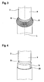
- Fig. 3 is one compared to Fig. 1 alternative embodiment of the upper portion 4 of the bearing shaft 3 shown.
- the knurling section 9 no longer extends parallel to the longitudinal central axis L of the bearing shaft 3, but tapers conically in the direction of the upper free end of the bearing shaft 3.
- collar 13 are omitted.
- the passage opening 8 in the bearing plate 5 has to be shaped congruent, ie with a tapering cross section.
- a further alternative embodiment of a bearing shaft 3 is shown. It can be seen that this has a polygonal section 19 for rotationally fixed fixing of the bearing plate 5. Immediately below the polygonal section 19, the bearing shaft 3 has a diameter step 20, on which the bearing plate 5 can rest in the mounted state.
- Fig. 5 is the bearing shaft 3 according to Fig. 1 without bearing plate 5 shown.
- Fig. 5 is the bearing shaft 3 according to Fig. 1 without bearing plate 5 shown.
- Fig. 6 is the bearing shaft 3 according to Fig. 5 shown in isolation without bearing housing, wherein the knurl section extends parallel to the longitudinal center axis L of the bearing shaft 3.
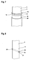
- a bearing shaft 3 is shown in the upper portion 4, a circumferential groove 15 is introduced, in which a securing ring 16 of the securing means 14 is held.
- a polygonal section 19 with two parallel flattening is provided for supporting the bearing plate 5, not shown.
- securing means 14 are shown by way of example which comprise a bolt 21 which passes through the bearing shaft 3, more precisely the upper portion 4 of the bearing shaft 3, in the transverse direction.
- the bolt 21 lies with its underside on the bearing plate. Break points 22 in the outer end portions of the bolt 21 break when a maximum allowable axial force is exceeded, whereupon the upper portion 4 of the bearing shaft 3 can move into the bearing housing, not shown.
Landscapes
- Engineering & Computer Science (AREA)
- Mechanical Engineering (AREA)
- Mounting Of Bearings Or Others (AREA)
- Shafts, Cranks, Connecting Bars, And Related Bearings (AREA)
Claims (9)
- Palier d'essuie-glace comprenant un arbre de palier (3) reçu en partie dans un boîtier de palier (2), dont la portion supérieure (4) présentant une région de fixation (7) pour la fixation d'un bras d'essuie-glace fait saillie hors du boîtier de palier (2), une plaque de palier (5), formant conjointement avec l'arbre de palier (3) une manivelle d'entraînement, étant connectée de manière solidaire en rotation à la portion supérieure (4) de l'arbre de palier (3), la portion supérieure (4) de l'arbre de palier (3) étant fixée avec des moyens de fixation (14) à l'encontre d'un mouvement relatif axial par rapport à la plaque de palier (5) dans la direction du boîtier de palier (2), les moyens de fixation (14) étant réalisés et/ou disposés de telle sorte que lors d'un dépassement d'une force axiale prédéfinie maximale agissant sur l'arbre de palier (3), ceux-ci permettent un mouvement axial relatif de la portion supérieure (4) de l'arbre de palier (3) dans la direction du boîtier de palier (2), une portion inférieure (11) de l'arbre de palier (3), faisant saillie hors du boîtier de palier (2), étant fixée à l'aide de moyens de fixation supplémentaires (10) à l'encontre d'un mouvement relatif axial dans la direction du boîtier de palier (2),
caractérisé en ce que
l'arbre de palier (3) présente un épaulement de diamètre (20) qui est disposé sur l'arbre de palier (3) de telle sorte que la plaque de palier (5) repose sur l'épaulement de diamètre (20), et en ce que les moyens de fixation (14) présentent un boulon (21) s'étendant de préférence perpendiculairement à l'axe médian longitudinal de l'arbre de palier et/ou un écrou rapide, qui est/sont pourvus d'au moins une zone destinée à la rupture (22). - Palier d'essuie-glace selon la revendication 1, caractérisé en ce que les moyens de fixation (14) sont disposés dans une région axialement entre la région de fixation (7) pour la fixation du bras d'essuie-glace et la plaque de palier (5), de préférence de telle sorte qu'ils reposent sur la plaque de palier (5).
- Palier d'essuie-glace selon l'une quelconque des revendications précédentes, caractérisé en ce que la plaque de palier (5) est connectée au moyen, de préférence exclusivement, d'une connexion par engagement par correspondance de formes, de manière solidaire en rotation à la portion supérieure (4) de l'arbre de palier (3).
- Palier d'essuie-glace selon la revendication 3, caractérisé en ce que la connexion par engagement par correspondance de formes est réalisée de telle sorte qu'elle ne provoque au moins approximativement aucune force de retenue agissant à l'encontre d'un déplacement de réglage axial de la portion supérieure (4) de l'arbre de palier (3) dans la direction du boîtier de palier (2).
- Palier d'essuie-glace selon la revendication 3 ou 4, caractérisé en ce que la connexion par engagement par correspondance de formes comprend une portion polygonale (19) ou une portion moletée (9) de la portion supérieure (4) de l'arbre de palier (3), qui coopère par transmission de couple avec une ouverture de passage de la plaque de palier (5) ayant un contour de forme adaptée (8).
- Palier d'essuie-glace selon la revendication 5, caractérisé en ce que la portion polygonale (19) ou la portion moletée (9), au moins dans une portion axiale, sont réalisées en se rétrécissant dans la direction de l'extrémité supérieure de l'arbre de palier (3).
- Procédé de montage pour le montage d'un palier d'essuie-glace (1) selon l'une quelconque des revendications précédentes, dans lequel la portion supérieure (4) de l'arbre de palier (3) est fixée avec des moyens de fixation (14) à l'encontre d'un mouvement relatif axial par rapport à la plaque de palier (5) dans la direction du boîtier de palier (2), les moyens de fixation (14) étant réalisés et/ou disposés de telle sorte que lors du dépassement d'une force axiale prédéfinie maximale agissant sur l'arbre de palier (3), ils permettent un mouvement axial relatif de la portion supérieure (4) de l'arbre de palier (3) dans la direction du boîtier de palier (2), une portion inférieure (11) de l'arbre de palier (3), faisant saillie hors du boîtier de palier (2), étant fixée à l'aide de moyens de fixation supplémentaires (10) à l'encontre d'un mouvement relatif axial dans la direction du boîtier de palier (2),
caractérisé en ce
qu'un épaulement de diamètre (20) est prévu sur l'arbre de palier (3), sur lequel la plaque de palier (5) repose dans l'état monté, et en ce que les moyens de fixation (14) présentent un boulon (21) s'étendant de préférence perpendiculairement à l'axe médian longitudinal de l'arbre de palier et/ou un écrou rapide, qui est/sont pourvus d'au moins une zone destinée à la rupture (22). - Procédé de montage selon la revendication 7, caractérisé en ce que la plaque de palier (5) est connectée de manière solidaire en rotation à la portion supérieure (4) de l'arbre de palier (3) de telle sorte que la connexion solidaire en rotation ne provoque au moins approximativement aucune force de retenue agissant à l'encontre d'un déplacement de réglage axial de la portion supérieure (4) de l'arbre de palier (3) dans la direction du boîtier de palier (2).
- Procédé de montage selon la revendication 8, caractérisé en ce que la plaque de palier (5) est d'abord pressée sur la portion supérieure (4) de l'arbre de palier (3), est à nouveau desserrée et est ensuite à nouveau montée.
Applications Claiming Priority (1)
| Application Number | Priority Date | Filing Date | Title |
|---|---|---|---|
| DE200710061102 DE102007061102A1 (de) | 2007-12-19 | 2007-12-19 | Wischerlager |
Publications (3)
| Publication Number | Publication Date |
|---|---|
| EP2072358A2 EP2072358A2 (fr) | 2009-06-24 |
| EP2072358A3 EP2072358A3 (fr) | 2010-10-20 |
| EP2072358B1 true EP2072358B1 (fr) | 2015-02-25 |
Family
ID=40510440
Family Applications (1)
| Application Number | Title | Priority Date | Filing Date |
|---|---|---|---|
| EP20080105631 Ceased EP2072358B1 (fr) | 2007-12-19 | 2008-10-22 | Palier d'essuie-glace |
Country Status (2)
| Country | Link |
|---|---|
| EP (1) | EP2072358B1 (fr) |
| DE (1) | DE102007061102A1 (fr) |
Families Citing this family (4)
| Publication number | Priority date | Publication date | Assignee | Title |
|---|---|---|---|---|
| DE102008042585A1 (de) | 2008-10-02 | 2010-04-08 | Robert Bosch Gmbh | Scheibenwischervorrichtung |
| DE102009046203A1 (de) * | 2009-10-30 | 2011-05-12 | Robert Bosch Gmbh | Antriebseinrichtung in einer Scheibenwischvorrichtung eines Fahrzeugs |
| FR3063315B1 (fr) * | 2017-02-27 | 2021-05-14 | Valeo Systemes Dessuyage | Carter d'un groupe motoreducteur associe a un arbre de sortie apte a mouvoir un systeme d'essuyage pour une surface vitree d'un vehicule automobile |
| FR3069507B1 (fr) * | 2017-07-28 | 2019-10-11 | Valeo Systemes D'essuyage | Ensemble maneton-manivelle d'un mecanisme de transmission de mouvement d'un systeme d'essuie-glace |
Family Cites Families (6)
| Publication number | Priority date | Publication date | Assignee | Title |
|---|---|---|---|---|
| JPH11139256A (ja) * | 1997-11-11 | 1999-05-25 | Jidosha Denki Kogyo Co Ltd | 自動車用ワイパー |
| FR2774340B1 (fr) * | 1998-01-30 | 2000-03-10 | Valeo Systemes Dessuyage | Mecanisme d'essuie-glace de vehicule automobile |
| US6845540B1 (en) * | 2002-04-30 | 2005-01-25 | Valeo Electrical Systems, Inc. | Wiper pivot housing with spring release pivot shaft |
| US7191487B2 (en) * | 2002-12-30 | 2007-03-20 | Valeo Electrical Systems, Inc. | Vehicle wiper apparatus with energy absorption collapsible pivot shaft |
| DE102004005065A1 (de) * | 2003-09-30 | 2005-04-14 | Robert Bosch Gmbh | Scheibenwischvorrichtung, insbesondere für ein Kraftfahrzeug |
| DE102006027345B4 (de) * | 2006-06-13 | 2018-03-22 | Valeo Wischersysteme Gmbh | Wischanlage für Fahrzeugscheiben |
-
2007
- 2007-12-19 DE DE200710061102 patent/DE102007061102A1/de not_active Ceased
-
2008
- 2008-10-22 EP EP20080105631 patent/EP2072358B1/fr not_active Ceased
Also Published As
| Publication number | Publication date |
|---|---|
| DE102007061102A1 (de) | 2009-06-25 |
| EP2072358A3 (fr) | 2010-10-20 |
| EP2072358A2 (fr) | 2009-06-24 |
Similar Documents
| Publication | Publication Date | Title |
|---|---|---|
| EP2229300B1 (fr) | Entrainement d'essuie-glace | |
| WO2005028217A1 (fr) | Ensemble moyeu de roue/joint tournant | |
| EP3434934B1 (fr) | Dispositif d'entraînement de broche | |
| EP3565976B1 (fr) | Dispositif de limitation de couple comportant trois brides | |
| EP1926641A1 (fr) | Dispositif essuie-glace, en particulier pour un véhicule à moteur | |
| DE19755899C2 (de) | Antriebseinheit für Verstelleinrichtungen | |
| EP2072358B1 (fr) | Palier d'essuie-glace | |
| DE102020205968A1 (de) | Spindeltriebeinheit für einen elektromechanischen Bremsdruckerzeuger, elektromechanischer Bremsdruckerzeuger | |
| EP0798181A1 (fr) | Palier d'entraînement d'un essuie-glace | |
| DE10011821B4 (de) | Fahrzeug-Scheibenwischvorrichtung und Verfahren zum Anbau derselben | |
| EP1721084B1 (fr) | Systeme bielle-manivelle et piece usinee pour un systeme bielle-manivelle | |
| EP2123523B1 (fr) | Manivelle pour un entraînement d'essuie-glace et entraînement d'essuie-glace | |
| DE10109660B4 (de) | Sicherungsring und Befestigungsvorrichtung für eine Welle-Nabe-Verbindung | |
| EP2059694B1 (fr) | Systeme de transmission avec maintien axial | |
| EP1716026B1 (fr) | Dispositif essuie-glace | |
| DE102018129285A1 (de) | Radlager für ein Kraftfahrzeug | |
| EP1763460B1 (fr) | Dispositf de fixation d'un essuie-glace sur un vehicle automobile | |
| EP1567396A1 (fr) | Dispositif d'essuie-glace notamment pour vehicule automobile | |
| EP2276653A1 (fr) | Dispositif essuie-glace | |
| DE102008040695A1 (de) | Abtriebswelle-Wischerarm-Verbindung sowie Scheibenwischerantrieb | |
| DE19639593B4 (de) | Wischervorrichtung | |
| EP1913272B1 (fr) | Ensemble constitue d'un joint homocinetique et d'un moyeu de roue | |
| EP2102038A1 (fr) | Ensemble boîtier d'un système essuie-glace à assemblage vissé | |
| EP2512880B1 (fr) | Dispositif d'essuie-glace | |
| DE102020005565A1 (de) | Wischeinrichtung für eine Scheibe für einen Kraftwagen |
Legal Events
| Date | Code | Title | Description |
|---|---|---|---|
| PUAI | Public reference made under article 153(3) epc to a published international application that has entered the european phase |
Free format text: ORIGINAL CODE: 0009012 |
|
| AK | Designated contracting states |
Kind code of ref document: A2 Designated state(s): AT BE BG CH CY CZ DE DK EE ES FI FR GB GR HR HU IE IS IT LI LT LU LV MC MT NL NO PL PT RO SE SI SK TR |
|
| AX | Request for extension of the european patent |
Extension state: AL BA MK RS |
|
| PUAL | Search report despatched |
Free format text: ORIGINAL CODE: 0009013 |
|
| AK | Designated contracting states |
Kind code of ref document: A3 Designated state(s): AT BE BG CH CY CZ DE DK EE ES FI FR GB GR HR HU IE IS IT LI LT LU LV MC MT NL NO PL PT RO SE SI SK TR |
|
| AX | Request for extension of the european patent |
Extension state: AL BA MK RS |
|
| 17P | Request for examination filed |
Effective date: 20110420 |
|
| AKX | Designation fees paid |
Designated state(s): DE ES GB HU |
|
| 17Q | First examination report despatched |
Effective date: 20111122 |
|
| GRAP | Despatch of communication of intention to grant a patent |
Free format text: ORIGINAL CODE: EPIDOSNIGR1 |
|
| INTG | Intention to grant announced |
Effective date: 20140526 |
|
| GRAS | Grant fee paid |
Free format text: ORIGINAL CODE: EPIDOSNIGR3 |
|
| GRAA | (expected) grant |
Free format text: ORIGINAL CODE: 0009210 |
|
| AK | Designated contracting states |
Kind code of ref document: B1 Designated state(s): DE ES GB HU |
|
| REG | Reference to a national code |
Ref country code: GB Ref legal event code: FG4D Free format text: NOT ENGLISH |
|
| REG | Reference to a national code |
Ref country code: DE Ref legal event code: R096 Ref document number: 502008012692 Country of ref document: DE Effective date: 20150409 |
|
| PG25 | Lapsed in a contracting state [announced via postgrant information from national office to epo] |
Ref country code: ES Free format text: LAPSE BECAUSE OF FAILURE TO SUBMIT A TRANSLATION OF THE DESCRIPTION OR TO PAY THE FEE WITHIN THE PRESCRIBED TIME-LIMIT Effective date: 20150225 |
|
| REG | Reference to a national code |
Ref country code: DE Ref legal event code: R097 Ref document number: 502008012692 Country of ref document: DE |
|
| PLBE | No opposition filed within time limit |
Free format text: ORIGINAL CODE: 0009261 |
|
| STAA | Information on the status of an ep patent application or granted ep patent |
Free format text: STATUS: NO OPPOSITION FILED WITHIN TIME LIMIT |
|
| 26N | No opposition filed |
Effective date: 20151126 |
|
| GBPC | Gb: european patent ceased through non-payment of renewal fee |
Effective date: 20151022 |
|
| PG25 | Lapsed in a contracting state [announced via postgrant information from national office to epo] |
Ref country code: GB Free format text: LAPSE BECAUSE OF NON-PAYMENT OF DUE FEES Effective date: 20151022 |
|
| PG25 | Lapsed in a contracting state [announced via postgrant information from national office to epo] |
Ref country code: HU Free format text: LAPSE BECAUSE OF FAILURE TO SUBMIT A TRANSLATION OF THE DESCRIPTION OR TO PAY THE FEE WITHIN THE PRESCRIBED TIME-LIMIT; INVALID AB INITIO Effective date: 20081022 |
|
| PGFP | Annual fee paid to national office [announced via postgrant information from national office to epo] |
Ref country code: DE Payment date: 20231218 Year of fee payment: 16 |
|
| REG | Reference to a national code |
Ref country code: DE Ref legal event code: R119 Ref document number: 502008012692 Country of ref document: DE |
|
| PG25 | Lapsed in a contracting state [announced via postgrant information from national office to epo] |
Ref country code: DE Free format text: LAPSE BECAUSE OF NON-PAYMENT OF DUE FEES Effective date: 20250501 |