EP2072385B1 - Roboter - Google Patents
Roboter Download PDFInfo
- Publication number
- EP2072385B1 EP2072385B1 EP08253958A EP08253958A EP2072385B1 EP 2072385 B1 EP2072385 B1 EP 2072385B1 EP 08253958 A EP08253958 A EP 08253958A EP 08253958 A EP08253958 A EP 08253958A EP 2072385 B1 EP2072385 B1 EP 2072385B1
- Authority
- EP
- European Patent Office
- Prior art keywords
- robot
- posture
- joint mechanism
- requirement
- designated area
- Prior art date
- Legal status (The legal status is an assumption and is not a legal conclusion. Google has not performed a legal analysis and makes no representation as to the accuracy of the status listed.)
- Not-in-force
Links
- 230000007246 mechanism Effects 0.000 claims abstract description 133
- 210000001503 joint Anatomy 0.000 claims abstract description 72
- 230000003993 interaction Effects 0.000 claims abstract description 4
- 238000012937 correction Methods 0.000 claims description 34
- 238000009434 installation Methods 0.000 claims description 24
- 230000008859 change Effects 0.000 claims description 4
- 210000002414 leg Anatomy 0.000 abstract description 76
- 210000000629 knee joint Anatomy 0.000 abstract description 7
- 210000004394 hip joint Anatomy 0.000 abstract description 5
- 230000036544 posture Effects 0.000 description 104
- 210000003811 finger Anatomy 0.000 description 15
- 210000001624 hip Anatomy 0.000 description 14
- 238000010276 construction Methods 0.000 description 11
- 238000000034 method Methods 0.000 description 9
- 230000009471 action Effects 0.000 description 6
- 210000004247 hand Anatomy 0.000 description 5
- 210000003108 foot joint Anatomy 0.000 description 4
- 230000006870 function Effects 0.000 description 4
- 230000005540 biological transmission Effects 0.000 description 3
- 210000004932 little finger Anatomy 0.000 description 3
- 238000005259 measurement Methods 0.000 description 3
- 210000003813 thumb Anatomy 0.000 description 3
- 230000001133 acceleration Effects 0.000 description 2
- 239000013013 elastic material Substances 0.000 description 2
- 210000002310 elbow joint Anatomy 0.000 description 2
- 239000011159 matrix material Substances 0.000 description 2
- 210000000236 metacarpal bone Anatomy 0.000 description 2
- 210000000811 metacarpophalangeal joint Anatomy 0.000 description 2
- 238000012545 processing Methods 0.000 description 2
- 210000000323 shoulder joint Anatomy 0.000 description 2
- 238000013519 translation Methods 0.000 description 2
- 238000013459 approach Methods 0.000 description 1
- 210000003797 carpal joint Anatomy 0.000 description 1
- 238000010586 diagram Methods 0.000 description 1
- 210000005224 forefinger Anatomy 0.000 description 1
- 238000003384 imaging method Methods 0.000 description 1
- 230000009467 reduction Effects 0.000 description 1
Images






Classifications
-
- B—PERFORMING OPERATIONS; TRANSPORTING
- B25—HAND TOOLS; PORTABLE POWER-DRIVEN TOOLS; MANIPULATORS
- B25J—MANIPULATORS; CHAMBERS PROVIDED WITH MANIPULATION DEVICES
- B25J19/00—Accessories fitted to manipulators, e.g. for monitoring, for viewing; Safety devices combined with or specially adapted for use in connection with manipulators
- B25J19/005—Accessories fitted to manipulators, e.g. for monitoring, for viewing; Safety devices combined with or specially adapted for use in connection with manipulators using batteries, e.g. as a back-up power source
-
- B—PERFORMING OPERATIONS; TRANSPORTING
- B62—LAND VEHICLES FOR TRAVELLING OTHERWISE THAN ON RAILS
- B62D—MOTOR VEHICLES; TRAILERS
- B62D57/00—Vehicles characterised by having other propulsion or other ground- engaging means than wheels or endless track, alone or in addition to wheels or endless track
- B62D57/02—Vehicles characterised by having other propulsion or other ground- engaging means than wheels or endless track, alone or in addition to wheels or endless track with ground-engaging propulsion means, e.g. walking members
- B62D57/032—Vehicles characterised by having other propulsion or other ground- engaging means than wheels or endless track, alone or in addition to wheels or endless track with ground-engaging propulsion means, e.g. walking members with alternately or sequentially lifted supporting base and legs; with alternately or sequentially lifted feet or skid
Definitions
- the present invention relates to a robot which is capable of autonomously moving by the operation of a plurality of legs extending from a body.
- a method of connecting the first connector and the second connector in addition to the method in which the robot is moved relative to the charging installation, it may be possible to contemplate a method of driving the second connector by a drive provided for the charging installation so as to be brought close to the first connector in a state where the robot has been stopped.
- the position or the like of the first connector may become inappropriate from a viewpoint of connection with the second connector because of the fact that the position, posture, or position and posture (hereinafter properly referred to as "position or the like") of the second connector undesirably deviates from its inherent or original position and the like, or for the reason that there are inconvenient factors, such as inclination of a floor, or existence of irregularities in a floor on which the robot is positioned even though the robot stops with a designated posture in a designated position (or the robot per se recognizes that it stops with a designated posture in a designated position).
- the position or the like of the first connector may still remain unsuitable from a viewpoint of connection with the second connector. Additionally, when this moving distance becomes long, it is not preferable from a viewpoint of saving of consumption in energy of the robot.
- an object of at least preferred embodiments of the invention is to provide a robot capable of suitably adjusting the position or the like of its body on the current spot from a viewpoint of executing a designated task accompanied by the interaction with a target object.
- the present invention is concerned with a robot which includes a body, a plurality of legs connected to the body via a first leg joint mechanism, respectively, and having a second leg joint mechanism, respectively, and a controller, the robot being autonomously movable with repetition of causing the plurality of legs thereof to leave from and arrive at a floor (it will be hereinafter referred to as "floor-leaving and "floor-arriving" throughout the present application) as the movement of a leg joint mechanism group including the first leg joint mechanism and the second leg joint mechanism is controlled by the controller.
- a robot is disclosed in EP-A-1825966 .
- a robot in accordance with a first aspect of the present invention is characterised in that the controller comprises a first control element which determines whether or not a second position/posture requirement is satisfied that the position and posture of the body fall within a second target position range and a second target posture range, respectively, which are defined from a viewpoint that the robot is urged to execute a designated task, in a state where the robot is in standstill in a second designated area which is an execution area of the designated task accompanied by an interaction thereof with a target object, and which, if the determination is that the second position/posture requirement is not satisfied, further determines whether or not a correction requirement is satisfied that the second position/posture requirement is satisfied by executing a correction such that the position and posture of the body may not exceed a variable position range and a variable posture range, respectively, which are defined from a viewpoint such that the robot is permitted to stably stand, depending on the movement of the leg joint mechanism group while the robot permits the plurality of legs to be kept arrived at a floor, and a second control element
- the position or the like of the body is adjusted by controlling the movement of the leg joint mechanism group which comprises the first leg joint mechanism and the second leg joint mechanism, on a current spot of the robot, under a requirement that the "second position/posture requirement" is not satisfied. Accordingly, in a case where the position or the like of the body is inappropriate from a viewpoint of executing the designated task notwithstanding that the robot stops in the second designated area in order to execute the designated task, the robot can execute the designated task after the position or the like of the body has been corrected on the current spot in the second designated area.
- the "movement" of respective of the joint mechanism technically means movements which are defined by a part of or all of translational movements in the directions of three axes and rotations about the three axes in a rectangular coordinate system.
- the “robot stops” technically means a state where the movements of all of the leg joint mechanisms which belong to the leg joint mechanism group are stopped.
- the position or the like of the body is corrected by controlling the movement of the leg joint mechanism group on the current spot of the robot while the robot allows each foot to remain arrived at the floor, under a requirement such that it has been determined that the "correction requirement" is satisfied. Accordingly, the position or the like of the body can be appropriately corrected from the viewpoint of executing the designated task in the second designated area with each foot being kept arrived at the floor, while avoiding such a situation that the robot becomes unstable during standing thereof.
- a robot in accordance with certain embodiments of the present invention is further characterized in that there is further provided a plurality of feet as floor-arriving portions of the plurality of legs, which are respectively connected to ends of the plurality of legs via a third leg joint mechanism, and the second control element controls the movement of the leg joint mechanism group including the third leg joint mechanism in addition to the first leg joint mechanism and the second leg joint mechanism.
- the position as well as the variable range of a posture of the body can be flexibly extended by moving the third leg joint mechanism in addition to the first leg joint mechanism and the second leg joint mechanism.
- the second control element controls the movement of the leg joint mechanism group so as to be stopped again in the second designated area, after the robot has executed the floor-leaving and the floor-arriving of a part or all of the plurality of legs in the second designated area from a state where the robot keeps standstill thereof in the second designated area, under a requirement that the first control element determines that the second position/posture requirement and the correction element are not satisfied.
- the robot moves so as to perform stepping on the current spot thereof.
- the number of times of the floor-leaving and floor-arriving of the respective legs may be single time or multiple times, and may differ for respective legs.
- the position or the like of the body in the second designated area can be changed, so that the correction requirement may be satisfied.
- the position or the like of the body can be corrected In the second designated area with each foot being kept arrived at the floor to be appropriate from the viewpoint of executing the designated task, and avoiding a situation where the robot during standing thereof becomes unstable.
- the second control element controls the movement of the leg Joint mechanism group so that, after the robot has moved from the second designated area to another area, the robot is then moved to the second designated area to come to a standstill again there, under a requirement that the first control element has determined that the second position/posture requirement and the correction element are not still satisfied.
- the robot in a case where the "correction requirement" is not satisfied, the robot once moves from the second designated area to another area, and then moves back again to the second designated area, and comes to standstill there.
- the position or the like of the body in the second designated area can be changed so that the correction requirement may be satisfied.
- the position or the like of the body can be corrected in the second designated area with each foot being kept arrived at the floor to be appropriate from the viewpoint of executing the designated task, while avoiding a situation where the robot during standing thereof becomes unstable as mentioned above.
- the first control element determines whether or not a first position/posture requirement is satisfied that the position and posture of the body fall within a first target position range and a first target posture range, respectively, which are defined from a viewpoint such that the position and posture of the body are adjusted in advance in a first designated area so that an amount of correction of the position, posture, or the position and posture of the body in the second designated area may be reduced, in a state where the robot is in standstill in the first designated area different from the second designated area, and the second control element controls a movement of the leg Joint mechanism group so that the robot comes to standstill after the robot has moved from the first designated area to the second designated area, under a requirement such that the first control element has determined that the first position/posture requirement is satisfied.
- the robot has moved to the second designated area from the first designated area, and then comes to stop there, under the requirement that the "first position/posture requirement" is satisfied. Accordingly, the position or the like of the body in the first designated area can be appropriately corrected in advance from the viewpoint that the robot reduces the amount of correction, such as the position of the body in the second designated area, and smoothly executes the designated task.
- a robot in accordance with such embodiments may be further characterized in that the second control element controls the movement of the leg joint mechanism group so that, after the robot has executed the floor-leaving and floor-arriving of a part or all of the plurality of legs in the first designated area from a state where the robot is in standstill in the first designated area, under a requirement such that the first control element has determined that the first position/posture requirement is not still satisfied.
- the robot in cases where it has been determined that the "first position/posture requirement" is not satisfied, the robot operates so as to perform stepping on the current spot.
- the number of times of the floor-leaving and floor-arriving of the leg may be a single time or multiple times, and may differ for every leg.
- the robot can change the position or the like of the body in the first designated area so that the first position/posture requirement may be satisfied. Accordingly, when the robot has moved to the second designated area from the first designated area, the position or the like of the body in the first designated area can be appropriately corrected in advance from the viewpoint that the robot reduces the amount of correction, such as the position of the body in the first designated area, and smoothly executes the designated task.
- a battery and a first connector there are further provided a battery and a first connector, and a task of connecting a second connector behaving as the target object and driven by a drive source provided for a charging installation, to the first connector, and of charging the battery by the charging installation, is executed as the designated task.
- the designated task by which the second connector is connected to the first connector and the battery is charged by the charging installation can be executed after the robot corrected the position or the like of the body thereof on the current spot in the second designated area.
- a task of driving the second connector by the drive source of the charging installation in a state where the first and second connectors are connected together, thereby removing the second connector from the first connector, is executed as the designated task.
- the robot in a case where the position or the like of the body is inappropriate notwithstanding that the robot stops in the second designated area, there is such an unfavorable possibility that the second connector is not removed from the first connector, the position or the like of the body of the robot changes with the movement of the second connector, and the standing state of the robot becomes unstable.
- the robot can correct the position or the like of the body on the current spot in the second designated area as mentioned above. Accordingly, it is able to execute a designated task in which the second connector is surely removed from the first connector while avoiding an unfavorable situation such that the standing state of the robot becomes unstable because of the movement of the second connector.
- a task of handing the target object gripped by the hand to a human being or another robot is executed as the designated task.
- a robot 1 shown in FIG. 1 is a legged type mobile robot, and like a human being, includes a body 10, a head 11 arranged above the body 10, right and left arms 12 provided at an upper portion of the body 10 to extend from both upper sides, hands 13 provided respectively at the tips of the right and left arms 12, and right and left legs 14 provided to extend downward from a lower portion of the body 10.
- the robot 1 has a controller 100 which controls the operation thereof, and a battery 1100.
- the body 10 is constituted by an upper portion and a lower portion which are mutually interconnected up and down so as to relatively rotate about a yaw axis.
- the head 11 can be moved to conduct a rotation about the yaw axis and so on with respect to the body 10.
- the head 11 is loaded with a pair of right and left head cameras C 1 which can sense light in various frequency bands, such as a CCD camera or an infrared camera which has the front of the robot 1 as an imaging range.
- a lower portion of the body 10 is loaded with a waist camera (active sensor) C 2 for detecting reflected light of a near-infrared laser beam from an article when the laser beam is emitted towards the lower front of the robot 1, to measure the position, orientation and the like of the article.
- Each arm 12 includes a first arm link 122 and a second arm link 124.
- the body 10 and the first arm link 121 are movably connected together via a shoulder joint mechanism (a first arm joint mechanism) 121
- the first arm link 122 and the second arm link 124 are movably connected to one another via an elbow joint mechanism (a second arm joint mechanism) 123
- the second arm link 124 and the hand 13 are movably connected together via a carpal joint mechanism (a third arm joint mechanism) 125.
- the shoulder joint mechanism 121 has rotational degrees of freedom about roll, pitch, and yaw axes
- the elbow joint mechanism 123 has a rotational degree of freedom about the pitch axis
- the carpus joint mechanism 125 has rotational degrees of freedom about the roll, pitch, and yaw axes.
- the hand 13 includes five finger mechanisms 131 to 135 which extend from a palm, and correspond to the thumb, forefinger, middle finger, ring finger, and a little finger, respectively, of a human being's hand.
- the first finger mechanism 131 and the four finger mechanisms 132 to 135 which are laterally arrayed are disposed to oppose to one another.
- the first finger mechanism 131 includes three link members respectively corresponding to a first metacarpal bone, and a proximal phalanx and a distal phalanx of the thumb in the human being's hand, and an elastic cover which covers the three link members.
- the three link members are connected together via joints respectively corresponding to a joint on the side of a base part of the first metacarpal bone and a metacarpophalangeal joint and an interphalangeal joint of the thumb, in the human being's hand sequentially from the palm.
- the first finger mechanism 131 can be bent in each joint according to a force transmitted from a motor housed in the palm via a power transmission mechanism constituted by a speed reduction mechanism, etc.
- the power transmitted to the first finger mechanism 131 from the motor is controlled by a controller 100.
- the finger mechanisms 132 to 135 are adapted to have an identical construction to the finger mechanisms disclosed, for example, in Japanese Patent Application Laid-Open No. 2003-181787 , and are adapted to have almost the same construction as each other.
- the fifth finger mechanism 135 includes three link members respectively corresponding to a proximal phalanx, a middle phalanx and a distal phalanx of the little finger of the human being's hand, and an elastic cover which covers the three link members.
- the three link members are connected together via joints respectively corresponding to a metacarpophalangeal joint, a proximal interphalangeal joint, and a distal interphalangeal joint of the little finger of the human being's hand sequentially from the palm.
- the fifth finger mechanism 135 can be bent inward in each joint according to the power transmitted from a motor (not shown) serving as a power source via a power transmission mechanism.
- the power transmitted to the fifth finger mechanism 135 from the motor is controlled by a controller 100 similarly to the first finger mechanism 131.
- the power transmission mechanism may be constituted by a wire, a pulley and so on, as disclosed in the above-mentioned Japanese Patent Application Laid-Open No. 2003-181787 , and all constructions that can transmit the power of a motor so as to bend and stretch each finger mechanism may be adopted.
- Each leg 14 includes a first leg link 142, a second leg link 144, and a foot 15.
- the body 10 and the first leg link 142 are connected together via a hip joint mechanism (a first leg joint mechanism) 141
- the first leg link 142 and the second leg link 144 are connected together via a knee joint mechanism (a second leg joint mechanism) 143
- the second leg link 144 and the foot 15 are moveably connected together via a foot joint mechanism (a third leg joint mechanism) 145.
- the hip joint mechanism 141 has rotational degrees of freedom about roll, pitch, and roll axes
- the knee joint mechanism 143 has rotational degrees of freedom about the pitch axis
- the foot joint mechanism 145 has rotational degrees of freedom about roll and pitch axes.
- the hip joint mechanism 141, the knee joint mechanism 143, and the foot joint mechanism 145 constitute a "leg joint mechanism group.”
- translational and rotational degrees of freedom of each joint mechanism included in the leg joint mechanism group may be changed suitably.
- the leg joint mechanism group may be constructed by combinations of the two remaining joint mechanisms.
- the leg joint mechanism group may be constructed so as to include the second leg joint mechanism.
- the sole of the foot 15 is provided with an elastic material 152 as disclosed in Japanese Patent Application Laid-Open No. 2001-129774 .
- a first connector 1200 for charging the battery 1100 is provided on the back side of the body 10.
- first charging terminals 1220, terminals 1240 for a first signal, and tubes 1260 are provided in parallel in the first connector 1200.
- a side wall of each tube 1260 is partially cut out, thereby forming guides 1270.
- the robot 1 executes tasks, such as charging the battery 1100 by a charging installation 2 shown in FIG. 2 .
- the charging installation 2 includes a power source 2100 for charging, a charge controller 200 which controls the operation of the charging installation 2, a second connector 2200, and a connector drive mechanism 2300. Additionally, the charging installation 2 includes a first sensor 211 which detects a first mark M 1 provided at a heel of the robot 1, using light, such as infrared light, and a second sensor 212 which detects a second mark M 2 provided at the back of the body 10 of the robot 1, using light, such as infrared light.
- second charging terminals 2220, terminals 2240 for a first signal, and rods 2260 are provided in parallel in the second connector 2200 so as to protrude in a horizontal direction.
- a pair of pins 2270 is provided so as to protrude from side walls of each rod 2260.
- the rod 2260 is attached to the second connector 2200 in a state wherein its radial movement or wobbling is possible by a compliance mechanism.
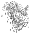
- the connector drive mechanism 2300 is a cylinder-type drive mechanism. As shown in FIG. 5 , the connector drive mechanism 2300 includes a foundation 230, a slider 2310 which has the second connector 2200 attached to a distal end thereof, a cylinder rod 2320 which makes the slider 2310 slide and reciprocate on the foundation 230, a compliance mechanism 2340 which holds the cylinder rod 2320 in a state where its radial movement or wobbling is possible, and a rod rotation driving mechanism 2360 which rotates the rod 2260 about an axis. The position of the second connector 2200 is measured on the basis of the amount of driving of the slider 2310 by the cylinder rod 2320. In addition, the second connector 2200 may be driven to advance or retreat in all the directions that the force of a horizontal component acts on the robot 1 at the time of retreat driving in addition to the horizontal direction.
- the first charging terminals 1220 and the second charging terminals 2220 are connected, the terminals 1240 for a first signal and the terminals 2240 for a second signal are connected, and the rods 2260 are inserted into tubes 1260, and the pins 2270 are engaged with terminal ends of the guides 1270.
- the first charging terminals 1220 and the second charging terminals 2220 are separated from each other, the terminals 1240 for a first signal and the terminals 2240 for a second signal are separated from each other, the pins 2270 are released from the engagement with the terminal ends of the guides 1270, and the rods 2260 are pulled out of the tubes 1260; respectively.
- the controller 100 shown in FIG. 6 is constituted by a CPU, a ROM, a RAM, an I/O, etc., and controls the operation of an actuator 1000 according to an action plan stored in a memory unit, on the basis of an output signal from each of sensors which constitute a sensor group 102, thereby controlling the action of the robot 1.
- the "action plan” is defined by a "target posture orbit” etc. showing a time-series changing mode of the target position of the robot 1, and a “target position track” showing a time-series changing mode of the target posture of the robot 1.
- an inclination angle sensor which outputs a signal according to the inclination angle or posture of the body 10 with respect to a horizontal plane
- a yaw rate sensor which outputs a signal according to the angular velocity the robot 1 about the yaw axis
- an acceleration sensor which outputs a signal according to the acceleration of the robot 1 in the directions of the roll axis, the pitch axis, etc.
- a rotary encoder which outputs a signal according to the angle of each joint, etc.
- a translation matrix or quaternion showing translation to the position in the fixed coordinate system is measured as the position of the body 10 on the basis of the output of the sensors which constitute the sensor group 102.
- the azimuth angle and elevation angle of a robot coordinate system in the fixed coordinate system in an +Z R direction, or a rotation matrix or quaternion showing the rotation by the azimuth angle and elevation angle in the fixed coordinate system are measured as the posture of the body 10.
- the controller 100 includes a first control element 110 which determines whether or not requirements to be described later are satisfied, and a second control element 120 which controls the operation of the robot 1 as described above according to the determined result by the first control element 110.
- the controller 100 may be a distributed controller constituted by a main control unit or a plurality of subcontrol units which are connected through an internal network of the robot 1.
- the robot 1 moves toward a first designated area ahead of the charging installation 2. Further, as shown in FIG. 9B , the robot 1 turns its back to the charging installation 2 and stops in the first designated area. Moreover, as shown in FIG. 9C , the robot 1 stops in a second designated area after having moved backward from the first designated area. Then, the robot 1 stops in the second designated area, and executes a "first designated task” and a "second designated task” in order.
- the "first designated task” is a task of charging the battery 1100 by the charging installation 2 after the second connector 2200 has been connected to the first connector 1200.
- the "second designated task” is a task of removing the second connector 2200 from the first connector 1200.
- the first control element 110 determines whether or not a "first position/posture requirement" is satisfied, in a state where the robot 1 has stopped in the first designated area ( FIG. 7 /S104).
- the "first position/posture requirement” is a requirement that the position and posture of the body 10 fall within a "first target position range” and a “first target posture range,” respectively.
- the "first target position range” and the “first target posture range” are defined from a viewpoint that the position and posture of the body 10 are adjusted in advance in the first designated area so that the amount of correction of the position or the like of the body 10 in the second designated area may be reduced, and are stored in the memory unit.
- the position and posture of the body 1 relative to the first floor mark FM 1 are measured as the position and posture of the body 1.
- the position and posture of the body 1 relative to the first floor mark FM 1 can be measured on the basis of such a measurement result that is obtained by firstly measuring the position and posture of the first floor mark FM 1 with respect to the waist camera C 2 through the waist camera C 2 , and the position, posture, etc. of the waist camera C 2 (or light-receiving element of the waist camera C 2 ) in the robot coordinate system that were stored in advance in the memory unit.
- the position and posture of the body 10 may be measured on the basis of an output signal from the rotary encoder showing the angle of each joint mechanism, and the output from other sensors, such as a value measured according to an inverse-dynamic or geometric computation model on the basis of the length or the like of each link stored in advance in the memory unit. Additionally, whether or not the first position/posture requirement is satisfied may be determined according to whether or not the position and posture of the first floor mark FM 1 which are measured through the waist camera C 2 in a state where the robot 1 has stopped in the first area coincide with the target position and target posture, respectively, of the first floor mark FM 1 stored in the memory unit, or are in a predetermined error range.
- the movement of the leg joint mechanism group is controlled so as to be stopped again in the first designated area, after the robot 1 performs floor-leaving and floor-arriving of a part or all of the plurality of legs 14 in the first designated area ( FIG. 7 /S108). Hence, the position or the like of the body can be corrected while the robot 1 performs stepping on the spot.
- the second processing element 120 controls the movement or the like of the leg joint mechanism group so that the robot 1 may move backward to the second designated area from the first designated area as shown to FIG. 9C , and stop in the second designated area ( FIG. 7 /S106).
- the first control element 110 determines whether or not a "second position/posture requirement" is satisfied, in a state where the robot 1 keeps stopping in the second designated area ( FIG. 7 /YES in S110).
- the "second position/posture requirement” is a requirement that the position and posture of the body 10 fall within a "second target position range” and a “second target posture range,” respectively.
- the "second target position range” and the “second target posture range” are defined from a viewpoint that the robot 1 is made to reliably execute a designated task. At this time, the position and posture of the body 10 relative to the second floor mark FM 2 are measured as the position and posture of the body 10.
- the position and posture of the body 10 relative to the second floor mark FM 2 can be measured on the basis of such a measurement result that is obtained by firstly measuring the position and posture of the second floor mark FM 2 with respect to the waist camera C 2 through the waist camera C 2 , and the position, posture, etc. of the waist camera C 2 in the robot coordinate system that were stored in advance in the memory unit.
- the position and posture of the body 10 may be measured on the basis of an output signal from the rotary encoder showing the angle of each joint mechanism, and the output from other sensors, such as a value measured according to an inverse-dynamic or geometric computation model on the basis of the length or the like of each link stored in advance in the memory unit.
- whether or not the second position/posture requirement is satisfied may be determined according to whether or not the position and posture of the first floor mark FM 1 which are measured through the waist camera C 2 in a state where the robot 1 has stopped in the first area coincide with the target position and target posture, respectively, of the second floor mark FM 2 stored in the memory unit, or are in a predetermined error range.
- the first control element 110 determines whether or not a "correction requirement" is satisfied 110 ( FIG. 7 /S114).
- the "correction requirement” is a requirement that the second position/posture requirement is satisfied by adjusting the movement of the leg joint mechanism group on the spot while the robot 1 allows the plurality of legs 14 or feet 15 to arrive at a floor, thereby performing correction so that the position and posture of the body 10 may not exceed a "variable position range” and a “variable posture range,” respectively.
- the “variable position range” and the “variable posture range” are defined from a viewpoint that the robot 1 stably maintains its standing state, such that the position of ZMP falls within an allowable range so as not to deviate therefrom.
- the second control element 120 controls the movement of the leg joint mechanism group so that, while the robot 1 allows the plurality of feet 15 to arrive at a floor, the position or the like of the body 10 may be changed on the spot ( FIG. 7 /S116).
- an action plan including a target joint angle orbit showing a time-series changing mode of a target joint angle about each axis of each joint mechanism is generated, and the movement of each joint mechanism is controlled so that a joint angle orbit may follow this target angle orbit.
- the position of the body 10 can be shifted as indicated by arrows in a direction of an X R axis (roll axis), in a direction of a Y R axis (pitch axis), and in a direction of a Z R axis (yaw axis) in a state the foot 15 arrives at the floor.
- the posture of the body 10 can be corrected by the rotations as indicated by arrows around the directions of the roll axis, the pitch axis, and the yaw axis in a state the foot 15 is brought to arriving at the floor.
- the second control element 120 controls the movement or the like of the leg joint mechanism group so that the robot 1 may move to the first designated area where the position or the like thereof is suitably corrected, then move to the second designated area, and then stop again in the second designated area (refer to FIG. 7 /S102, S106, S108, etc.).
- the movement or the like of the leg joint mechanism group may be controlled so that the robot may return to and then stop in the second designated area.
- the second control element 120 determines whether or not execution of a designated task is completed ( FIG. 7 /S112). If it has been determined that the execution of the designated task is not completed ( FIG. 7 /NO in S112), the controller 100 controls the operation of the robot 1 so that the execution of the designated task may be started or continued ( FIG. 7 /S118). The first control element 110 determines whether or not the "second position/posture requirement" is satisfied, even during the execution of the designated task by the robot 1 ( FIG. 7 /S120).
- the robot 1 while the robot 1 is executing the designated task, whether or not a requirement that the posture of the body 10 falls within the second target posture range or a requirement that the position of the body 10 falls within the second target position range is satisfied instead of the second position/posture requirement may be determined. Then, if the first control element 110 determines that the second position/posture requirement is not satisfied ( FIG. 7 /NO in S120), the position or the like of the body 10 etc. is corrected as the second control element 120 controls the movement of the leg joint mechanism group while the robot 1 has allowed the foot 15 to arrive at a floor ( FIG. 7 /S122). Then, the second control element 120 determines whether or not the execution of a designated task is completed ( FIG. 7 /S112).
- the second control element 110 determines that the second position/posture requirement is satisfied ( FIG. 7 /YES in S120)
- the second control element 120 determines whether or not the execution of the designated task is completed ( FIG. 7 /S112). If it has been determined that the execution of the designated task is completed ( FIG. 7 /YES in S112), a series of processing mentioned above is completed.
- connector locking is executed ( FIG. 8 /S210).
- the distal ends of the rods 2260 are inserted into the tubes 1260, and the pins 2270 are guided to the distal ends of the guides 1270.
- the connector locking is executed as the rods 2260 are rotationally driven in a given direction about an axis by the rod rotation driving mechanism 2360. At this time, the second connector 2200 is driven forward so as to assist in realization of the connector locking.
- the rods 2260 are gradually inserted into the tubes 1260, and the pins 2270 are engaged with the terminal ends of the guides 1270, thereby realising the connector locking.
- the second connector 2200 and the first connector 1200 are brought into a connected state by the realization of the connector locking. That is, the second charging terminals 2220 and the first charging terminals 1220 are connected together, and the terminals 2240 for a second signal and the terminals 1240 for a first signal are connected together.
- the forward driving of the second connector 2200 is stopped ( FIG. 8 /S214).
- the charge controller 200 communicates with the controller 100 via the terminals 1240 for a first signal and the terminals 2240 for a second signal, thereby supplying a charging current to the battery 1100 via the first charging terminals 1220 and the second charging terminals 2220 from the power source 2100 for charging, recognizing the residual capacity or the like of the battery 1100 ( FIG. 8 /S216).
- the charge controller 200 determines on the basis of an output signal from the controller 100 that the charging of the battery 1100 has been completed ( FIG. 8 /YES in S218), the supply of an electric current to the battery 1100 from the power source 2100 for charging is stopped ( FIG. 8 /S220).
- the robot 1 executes the "first designated task" that the battery 1100 is charged by the charging installation 2 after having connected the second connector 2200 to the first connector 1200.
- connector unlocking is executed ( FIG. 8 /S222).
- the rods 2260 are rotationally driven about an axis in a direction opposite to a direction at the time of connector locking driving by the rod rotation driving mechanism 2360.
- the second connector 2200 may be driven backward so as to assist in realization of the connector unlocking.
- the pins 2270 provided so as to protrude from the side walls of the rods 2260 are guided by the guides 1270 of the tubes 1260, the rods 2260 are pulled out of the tubes 1260, thereby realizing the connector unlocking.
- the first charging terminals 1220 and the second charging terminals 2220 are separated from each other, and the terminals 1240 for a first signal and the terminals 2240 for a second signal are separated from each other, whereby the second connector 2200 is removed from the first connector 1200.
- the second connector 2200 is driven backward by the connector drive mechanism 2300 ( FIG. 8 /S226). Then, under a requirement that it have been determined that the second connector 2200 has returned to its initial position ( FIG. 8 /YES in S228), the backward driving of the second connector 2200 is stopped ( FIG. 8 /S230). In this step, the robot 1 executes the "second designated task" that the second connector 2200 is removed from the first connector 1200.
- the robot 1 which exhibits the above functions, while the robot 1 had allowed each foot 15 to arrive at a floor, the movement of the leg joint mechanism group is controlled on the spot under a requirement the "second position/posture requirement" is satisfied in a state where the robot has stopped in the second designated area. Thereby, the position or the like of the body 10 can be adjusted (refer to FIG. 7 /YES in S110, 116, FIG. 10 , and FIG. 11 ).
- the robot 1 can execute the designated tasks after the position or the like of the body 10 is suitably executed on the spot in the second designated area (refer to FIG. 7 /S118).
- factors that the second position/posture requirement is no longer satisfied when the robot has stopped in the second designated area include some asymmetry properties of operating characteristics of the robot 1, such as the inclination angle or existence of irregularities, of a floor where the robot 1 is standing, the inclination angle of a floor while the robot 1 is moving to the second designated area from the first designated area, the variation of a coefficient of friction, and the elastic property of the elastic material 152 of the right and left feet 15 of the robot 1.
- the position or the like of the body 10 can be suitably corrected in the second designated area by controlling the movement of the leg joint mechanism group in a state where the robot allowed each foot 15 to arrive at a floor so that the second position/posture requirement may be satisfied even while the robot 1 executes the designated task (refer to FIG. 7 /S120, and S122). Accordingly, the position or the like of the body 10 can be corrected and a designated task can be continued and executed, as mentioned above, even in a case where the second position/posture requirement is no longer satisfied due to any disturbance generated after the start of execution of the designated task.
- the robot 1 can modify the position or the like of the body 10 by moving some or all of the leg joint mechanism group delicately while the robot allowed each foot 15 to arrive at a floor in the second designated area (refer to FIGS. 10 and 11 ). Also, the first designated task that the second connector 2200 is connected to the first connector 1200 and the battery 1100 is charged by the charging installation 2 can be executed.
- FIG. 12B a situation where the robot 1 is pulled backward toward the second connector 2200 and its posture is collapsed a little is considered for the reasons that the rods 2260 are caught on the tubes 1260 although the connector locking has succeeded while the robot 1 executes the second designated task.
- the robot 1 can modify the position or the like of the body 10 by moving some or all of the leg joint mechanism group delicately while the robot allowed each foot 15 to arrive at a floor in the second designated area (refer to FIGS. 10 and 11 ).
- the second designated task that the second connector 2200 is removed from the first connector 1200 can be executed by making the charging installation 2 drive the second connector 2200.
- the position or the like of the body 10 is corrected by controlling the movement of the leg joint mechanism group on the spot while the robot 1 allowed each foot to arrive at a floor, under a requirement that it has been determined that the "correction requirement" is satisfied in addition to the second position/posture requirement (refer to FIG. 7 /YES in S114, and S116). Accordingly, the position or the like of the body 10 can be appropriately corrected from the viewpoint of execution of a designated task in the second designated area with each foot 15 arriving at the floor while avoiding a situation where a standing state of the robot 1 becomes unstable.
- the robot 1 in a case where it has been determined that the "correction requirement" is not satisfied, that is, in a case where a state where the robot 1 is standing may become unstable if the position or the like of the body 10 is corrected on the spot while the robot 1 allowed each foot 15 to arrive at a floor, the robot 1 once moves to the first designated area (other areas) from the second designated area, and corrects the position or the like of the body 10. Then, the robot 1 moves to the second designated area again, and stops there (refer to FIG. 7 /NO in S114, S104, S106, S108, and FIG. 9B and 9C ). As a result, the position or the like of the body 10 in the second designated area can be changed so that the correction requirement may be satisfied.
- the position or the like of the body 10 can be suitably corrected from the viewpoint of execution of a designated task in the second designated area, avoiding a situation where a state where the robot is standing becomes unstable, while the robot 1 allowed each foot 15 to arrive at a floor (refer to FIG. 7 /YES in S114, and S116).
- the operation of the robot 1 may be controlled so that the robot may perform stepping in the second designated area. Even in this case, the position or the like of the body 10 in the second designated area can be changed so that the correction requirement may be satisfied.
- the robot 1 has moved to the second designated area from the first designated area, and then stops there, under a requirement that the "first position/posture requirement" is satisfied ( FIG. 7 /YES in S104, and S106). Accordingly, the position or the like of the body 10 in the first designated area can be suitably corrected in advance from a viewpoint that the robot 1 reduces the amount of correction, such as the position of the body 10 in the second designated area, and smoothly executes a designated task.
- the robot 1 operates so as to perform stepping on the spot (refer to FIG. 7 /NO in S104, and S108).
- the robot 1 can change the position or the like of the body 10 in the first designated area so that the first position/posture requirement may be satisfied. Accordingly, when the robot 1 has moved to the second designated area from the first designated area, the position or the like of the body 10 in the first designated area can be suitably corrected in advance from a viewpoint that the robot reduces the amount of correction, such as the position of the body 10 in the first designated area, and smoothly executes a designated task.
- the robot 1 may execute various designated tasks different from the first designated task and the second designated task.
- the robot 1 can execute the designated task after the position or the like of the body 10 is suitably modified, while the robot allowed each foot 15 to arrive at a floor in the second designated area.
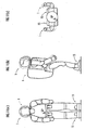
- the robot 1 may execute a designated task of gripping a tray (target object) W 1 with the hands 13.
- the robot 1 determines whether or not the second position/posture requirement is satisfied according to whether or not the position and posture of the tray W 1 coincide with a reference position and a reference posture stored in the memory unit, after the robot has recognized the position and posture of the tray W 1 on the basis of an image of the tray W 1 obtained through the head camera C 1 . Additionally, as shown in FIG.
- the robot 1 may execute a designated task of gripping a handle (target object) H or the like of a carriage W 2 .
- the robot 1 determines whether or not the second position/posture requirement is satisfied according to whether or not the position and posture of the carriage W 2 coincide with a reference position and a reference posture stored in the memory unit, after the robot has recognized the position and posture of the carriage W 2 on the basis of an image given to the lower side of the carriage W 2 obtained through the waist camera C 2 .
- the robot 1 may execute a designated task of handing a target object, such as the tray W 1 gripped by the hands 13, to a human being or the other robot 1.
- the robot 1 determines whether or not the second position/posture requirement is satisfied according to whether or not the position and posture of the tray W 1 coincide with a reference position and a reference posture stored in the memory unit, after the robot has recognized the position and posture of the floor mark FM on the basis of an image of the floor mark FM obtained through the waist camera C 2 .
Landscapes
- Engineering & Computer Science (AREA)
- Mechanical Engineering (AREA)
- Robotics (AREA)
- Chemical & Material Sciences (AREA)
- Combustion & Propulsion (AREA)
- Transportation (AREA)
- Manipulator (AREA)
- Container, Conveyance, Adherence, Positioning, Of Wafer (AREA)
Claims (10)
- Roboter, umfassend
einen Körper (10),
eine Mehrzahl von Beinen (14), die mit dem Körper jeweils mittels eines ersten Beingeienkmechanismus (141) verbunden sind und jeweils einen zweiten Beingelenkmechanismus (143) aufweisen, und
eine Regel-/Steuereinrichtung (100),
wobei der Roboter autonom beweglich ist, indem er wiederholt bewirkt, dass die Mehrzahl von Beinen (14) davon, ein Boden-Verlassen und ein Boden-Ankommen ausführt, wenn eine Bewegung einer Beingelenkmechanismus-Gruppe, welche den ersten Beingelenkmechanismus (141) und den zweiten Beingelenkmechanismus (143) umfasst, durch die Regel-/Steuereinrichtung (100) geregelt/gesteuert ist,
dadurch gekennzeichnet,
dass die Regel-/Steuereinrichtung (100) umfasst:ein erstes Regel-/Steuerelement (110), welches bestimmt, ob eine zweite Positions-/Stellungsbedingung, dass eine Position und eine Stellung des Körpers (10) innerhalb eines zweiten Zielpositionsbereiches beziehungsweise eines zweiten Zielstellungsbereiches liegt, erfüllt ist oder nicht, welche unter einem Gesichtspunkt definiert sind, dass der Roboter angetrieben wird, eine bestimmte Aufgabe auszuführen in einem Zustand, in welchem der Roboter in einem Stillstand in einem zweiten bestimmten Bereich ist, welcher ein Ausführungsbereich der durch eine Interaktion mit einem Zielobjekt begleiteten, bestimmten Aufgabe ist, undwelcher, falls die Bestimmung derart ist, dass die zweite Positions-/Stellungsbedingung nicht erfüllt ist, ferner bestimmt, ob eine Korrekturbedingung erfüllt ist oder nicht, dass die zweite Positions-/Stellungsbedingung durch Ausführen einer Korrektur erfüllt ist, derart, dass die Position und die Stellung des Körpers (10) einen variablen Positionsbereich beziehungsweise einen variablen Stellungsbereich nicht überschreiten dürfen, welche unter einem Gesichtspunkt derart definiert sind, dass dem Roboter ermöglicht wird, stabil zu stehen, in Abhängigkeit von der Bewegung der Beingelenkmechanismus-Gruppe, während der Roboter der Mehrzahl von Beinen (14) ermöglicht, an einem Boden angekommen gehalten zu werden; undein zweites Regel-/Steuerelement (120), welches die Bewegung der Beingelenkmechanismus-Gruppe regelt/steuert, um die Position, die Stellung oder die Position und die Stellung des Körpers (10) zu ändern, während die Mehrzahl von Beinen (14) an einem Boden angekommen gehalten werden, unter einer Bedingung, dass das erste Regel-/Steuerelement (110) bestimmt, dass die zweite Positions-/Stellungsbedingung noch nicht erfüllt ist und dass die Korrekturbedingung erfüllt ist. - Roboter nach Anspruch 1, ferner umfassend:eine Mehrzahl von Füßen (15), als Boden-ankommende Abschnitte der Mehrzahl von Beinen (14), welche jeweils mit Enden der Mehrzahl von Beinen mittels eines dritten Beingelenkmechanismus (145) verbunden sind,wobei das zweite Regel-/Steuerelement (120) die Bewegung der Beingelenkmechanismus-Gruppe regelt/steuert, welche zusätzlich zum ersten Beingelenkmechanismus (141) und zweiten Beingelenkmechanismus (143), den dritten Beingelenkmechanismus (145) umfasst.
- Roboter nach Anspruch 1 oder 2,
wobei das zweite Regel-/Steuerelement (120) die Bewegung der Beingelenkmechanismus-Gruppe derart regelt/steuert, dass diese im zweiten bestimmten Bereich erneut gestoppt ist, nachdem der Roboter das Boden-Verlassen und das Boden-Ankommen eines Teils oder allen von der Mehrzahl von Beinen (14) im zweiten bestimmten Bereich aus einem Zustand ausgeführt hat, in welchem der Roboter in dem zweiten bestimmten Bereich in einem Stillstand desselben ist, unter einer Bedingung, dass das erste Regel-/Steuerelement (110) bestimmt, dass die zweite Positions-/Stellungsbedingung und das Korrekturelement nicht erfüllt sind. - Roboter nach Anspruch 1 oder 2,
wobei das zweite Regel-/Steuerelement (120) die Bewegung der Beingelenkmechanismus-Gruppe derart regelt/steuert, dass nachdem der Roboter sich aus dem zweiten bestimmten Bereich zu einem anderen Bereich bewegt hat, der Roboter dann erneut dort zu einem Stillstand bewegt wird, unter einer Bedingung, dass das erste Regel-/Steuerelement (110) bestimmt hat, dass die zweite Positions-/Stellungsbedingung und das Korrekturelement immer noch nicht erfüllt sind. - Roboter nach einem der Ansprüche 1 bis 4,
wobei das erste Regel-/Steuerelement (110) bestimmt, ob eine erste Positions-/Stellungsbedingung erfüllt ist oder nicht, dass die Position und die Stellung des Körpers innerhalb eines ersten Zielpositionsbereiches beziehungsweise eines erstens Zielstellungsbereiches liegt, die unter einem Gesichtspunkt derart definiert sind, dass die Position und die Stellung des Körpers (10) im Voraus in einem ersten bestimmten Bereich angepasst sind, so dass ein Betrag der Korrektur der Position, der Stellung oder der Position und der Stellung des Körpers (10) im zweiten bestimmten Bereich reduziert werden kann, in einem Zustand, in welchem der Roboter im Stillstand im ersten bestimmten Bereich ist, welcher sich von dem zweiten bestimmten Bereich unterscheidet, und
das zweite Regel-/Steuerelement (120) eine Bewegung der Beingelenkmechanismus-Gruppe derart regelt-/steuert, dass der Roboter zum Stillstand kommt; nachdem der Roboter sich vom ersten bestimmten Bereich zum zweiten bestimmten Bereich bewegt hat, unter einer Bedingung, dass das erste Regel-/Steuerelement (110) bestimmt hat, dass die erste Positions-/Stellungsbedingung erfüllt ist. - Roboter nach Anspruch 5,
wobei das zweite Regel-/Steuerelement (120) die Bewegung der Beingelenkmechanismus-Gruppe derart regelt-/steuert, dass nachdem der Roboter das Boden-Verlassen und das Boden-Ankommen eines Teils oder von allen der Mehrzahl von Beinen (14) im ersten bestimmten Bereich aus einem Zustand, in welchem der Roboter im ersten bestimmten Bereich im Stillstand ist, ausgeführt hat, der Roboter erneut im ersten bestimmten Bereich anhält, unter einer Bedingung, derart dass das erste Regel-/Steuerelement bestimmt hat, dass die erste Positions-/Stellungsbedingung immer noch nicht erfüllt ist. - Roboter nach einem der Ansprüche 1 bis 6,
ferner umfassend eine Batterie (1100) und einen ersten Anschluss (1200), wobei eine Aufgabe des Verbindens eines zweiten Anschlusses (2200), der sich als das Zielobjekt verhält und durch eine für eine Aufladeinstallation (2) bereitgestellte Antriebsquelle angetrieben ist, mit dem ersten Anschluss (1200), und des Ladens der Batterie (1100) durch die Aufladeinstallation (2), als die bestimmte Aufgabe ausgeführt wird. - Roboter nach Anspruch 7,
wobei eine Aufgabe des Antreibens des zweiten Anschlusses (2200) durch die Antriebsquelle der Aufladeinstallation (2) in einem Zustand, in welchem der erste (1200) und der zweite (2200) Anschluss miteinander verbunden sind, wobei dabei der zweite Anschluss (2200) vom ersten Anschluss (1200) entfernt wird, als die bestimmte Aufgabe ausgeführt wird. - Roboter nach einem der Ansprüche 1 bis 8, ferner umfassend einen Arm (12), welcher mit dem Körper (10) mittels eines ersten Armgelenkmechanismus (121) gelenkig verbunden ist, und imstande ist, durch einen zweiten Armgelenkmechanismus (123) gebeugt und gestreckt zu werden, und
eine Hand (13), welche mit einem Ende des Arms (12) mittels eines dritten Armgelenks (125) gelenkig verbunden ist,
wobei der Roboter eine Aufgabe des Greifens des Zielobjektes mittels der Hand, als die bestimmte Aufgabe ausführt. - Roboter nach Anspruch 9,
wobei eine Aufgabe des Reichens des von der Hand ergriffenen Zielobjektes an einen menschlichen Wesen oder an einen anderen Roboter, als die bestimmte Aufgabe ausgeführt wird.
Applications Claiming Priority (1)
| Application Number | Priority Date | Filing Date | Title |
|---|---|---|---|
| JP2007318988A JP4552037B2 (ja) | 2007-12-10 | 2007-12-10 | ロボット |
Publications (2)
| Publication Number | Publication Date |
|---|---|
| EP2072385A1 EP2072385A1 (de) | 2009-06-24 |
| EP2072385B1 true EP2072385B1 (de) | 2010-09-15 |
Family
ID=40429955
Family Applications (1)
| Application Number | Title | Priority Date | Filing Date |
|---|---|---|---|
| EP08253958A Not-in-force EP2072385B1 (de) | 2007-12-10 | 2008-12-10 | Roboter |
Country Status (5)
| Country | Link |
|---|---|
| US (1) | US20090149993A1 (de) |
| EP (1) | EP2072385B1 (de) |
| JP (1) | JP4552037B2 (de) |
| AT (1) | ATE481299T1 (de) |
| DE (1) | DE602008002536D1 (de) |
Families Citing this family (22)
| Publication number | Priority date | Publication date | Assignee | Title |
|---|---|---|---|---|
| JP5213023B2 (ja) * | 2008-01-15 | 2013-06-19 | 本田技研工業株式会社 | ロボット |
| JP5948932B2 (ja) * | 2012-02-16 | 2016-07-06 | セイコーエプソン株式会社 | ロボット制御装置、ロボット制御方法およびロボット制御プログラムならびにロボットシステム |
| JP5898002B2 (ja) | 2012-06-28 | 2016-04-06 | 本田技研工業株式会社 | 移動ロボットの制御装置 |
| JP6111562B2 (ja) * | 2012-08-31 | 2017-04-12 | セイコーエプソン株式会社 | ロボット |
| JP6332900B2 (ja) | 2012-08-31 | 2018-05-30 | セイコーエプソン株式会社 | ロボットシステム及びロボット制御装置 |
| JP2014205197A (ja) | 2013-04-10 | 2014-10-30 | セイコーエプソン株式会社 | ロボット、ロボット制御装置およびロボットシステム |
| JP6155780B2 (ja) * | 2013-04-10 | 2017-07-05 | セイコーエプソン株式会社 | ロボット、ロボット制御装置およびロボットシステム |
| JP2014205199A (ja) | 2013-04-10 | 2014-10-30 | セイコーエプソン株式会社 | ロボット、ロボット制御装置およびロボットシステム |
| JP2014205198A (ja) | 2013-04-10 | 2014-10-30 | セイコーエプソン株式会社 | ロボット、ロボット制御装置およびロボットシステム |
| JP6354122B2 (ja) | 2013-06-05 | 2018-07-11 | セイコーエプソン株式会社 | ロボット |
| US9868209B2 (en) * | 2013-12-02 | 2018-01-16 | Seiko Epson Corporation | Robot |
| JP6524631B2 (ja) * | 2014-09-30 | 2019-06-05 | セイコーエプソン株式会社 | ロボット、制御装置およびロボットシステム |
| US10821614B2 (en) | 2016-11-11 | 2020-11-03 | Sarcos Corp. | Clutched joint modules having a quasi-passive elastic actuator for a robotic assembly |
| US11833676B2 (en) | 2020-12-07 | 2023-12-05 | Sarcos Corp. | Combining sensor output data to prevent unsafe operation of an exoskeleton |
| JP7478848B2 (ja) * | 2020-12-21 | 2024-05-07 | ファナック株式会社 | 教師データ生成装置、機械学習装置、及びロボット関節角度推定装置 |
| US11826907B1 (en) | 2022-08-17 | 2023-11-28 | Sarcos Corp. | Robotic joint system with length adapter |
| US11717956B1 (en) | 2022-08-29 | 2023-08-08 | Sarcos Corp. | Robotic joint system with integrated safety |
| WO2024098070A1 (en) | 2022-11-04 | 2024-05-10 | Sarcos Corp. | Robotic end-effector having dynamic stiffening elements with resilient spacers for conforming object interaction |
| US11897132B1 (en) | 2022-11-17 | 2024-02-13 | Sarcos Corp. | Systems and methods for redundant network communication in a robot |
| US11924023B1 (en) | 2022-11-17 | 2024-03-05 | Sarcos Corp. | Systems and methods for redundant network communication in a robot |
| US12290940B1 (en) | 2022-11-18 | 2025-05-06 | Agility Robotics, Inc. | Torso protrusion for robotic manipulation of objects and related technology |
| JP7672462B2 (ja) * | 2023-09-27 | 2025-05-07 | 本田技研工業株式会社 | 制御システム、制御方法、およびプログラム |
Family Cites Families (10)
| Publication number | Priority date | Publication date | Assignee | Title |
|---|---|---|---|---|
| JP2001088080A (ja) * | 1999-09-16 | 2001-04-03 | Denso Corp | 移動ロボットシステム |
| JP4279425B2 (ja) | 1999-11-05 | 2009-06-17 | 本田技研工業株式会社 | 脚式歩行ロボットの足部構造 |
| JP3914045B2 (ja) | 2001-12-17 | 2007-05-16 | 本田技研工業株式会社 | 多指ハンド装置 |
| JP4587738B2 (ja) * | 2003-08-25 | 2010-11-24 | ソニー株式会社 | ロボット装置及びロボットの姿勢制御方法 |
| JP4516344B2 (ja) * | 2004-04-12 | 2010-08-04 | 本田技研工業株式会社 | 脚式移動ロボット |
| CN100540237C (zh) * | 2004-08-02 | 2009-09-16 | 本田技研工业株式会社 | 腿式移动机器人的控制方法 |
| JP4531520B2 (ja) * | 2004-10-15 | 2010-08-25 | 本田技研工業株式会社 | 脚式移動ロボットの制御装置 |
| JP2006123854A (ja) * | 2004-11-01 | 2006-05-18 | Matsushita Electric Ind Co Ltd | 荷物運搬ロボット |
| JP4456560B2 (ja) * | 2005-12-12 | 2010-04-28 | 本田技研工業株式会社 | 脚式移動ロボット制御装置および脚式移動ロボット、並びに、脚式移動ロボット制御方法 |
| JP2007245332A (ja) * | 2006-02-14 | 2007-09-27 | Honda Motor Co Ltd | 脚式移動ロボットの充電システム |
-
2007
- 2007-12-10 JP JP2007318988A patent/JP4552037B2/ja not_active Expired - Fee Related
-
2008
- 2008-12-05 US US12/329,113 patent/US20090149993A1/en not_active Abandoned
- 2008-12-10 EP EP08253958A patent/EP2072385B1/de not_active Not-in-force
- 2008-12-10 AT AT08253958T patent/ATE481299T1/de not_active IP Right Cessation
- 2008-12-10 DE DE602008002536T patent/DE602008002536D1/de active Active
Also Published As
| Publication number | Publication date |
|---|---|
| ATE481299T1 (de) | 2010-10-15 |
| DE602008002536D1 (de) | 2010-10-28 |
| EP2072385A1 (de) | 2009-06-24 |
| US20090149993A1 (en) | 2009-06-11 |
| JP2009136997A (ja) | 2009-06-25 |
| JP4552037B2 (ja) | 2010-09-29 |
Similar Documents
| Publication | Publication Date | Title |
|---|---|---|
| EP2072385B1 (de) | Roboter | |
| JP5213023B2 (ja) | ロボット | |
| US20080133058A1 (en) | Robot, control method therefor and control program therefor | |
| KR101743926B1 (ko) | 로봇 및 그 제어방법 | |
| US7289884B1 (en) | Hand control system, method, program, hand, and robot | |
| EP2042275A2 (de) | Roboter, Steuerverfahren für den Roboter und Steuerprogramm für den Roboter | |
| Kofman et al. | Teleoperation of a robot manipulator using a vision-based human-robot interface | |
| JP5448326B2 (ja) | 把持装置および把持装置制御方法 | |
| JP4480843B2 (ja) | 脚式移動ロボット及びその制御方法、並びに、脚式移動ロボット用相対移動測定センサ | |
| KR20210102407A (ko) | 배측으로 지지되는 액츄에이션 메커니즘을 구비하는 로봇 엔드 이펙터 | |
| CN101646532B (zh) | 腿式移动机器人的控制方法以及腿式移动机器人 | |
| KR20120031595A (ko) | 로봇 및 그 제어방법 | |
| CN104589354A (zh) | 机器人控制装置、机器人系统以及机器人 | |
| KR20120074887A (ko) | 로봇 및 그 제어 방법 | |
| WO2022014133A1 (ja) | モバイルマニピュレータ及びその制御方法及びプログラム | |
| JP4033050B2 (ja) | ロボットハンドの把持制御装置 | |
| JP4485887B2 (ja) | 脚式移動ロボットの力センサ異常検知装置 | |
| WO2010001107A2 (en) | Method of controlling a robotic arm | |
| JP2002307340A (ja) | 脚式移動ロボット及びその制御方法 | |
| US10144130B2 (en) | Autonomous mobile system | |
| JP2016093853A (ja) | 移動ロボットの制御装置 | |
| JP7706893B2 (ja) | ロボットシステム、ロボットシステムの制御方法、ロボットシステムを用いた物品の製造方法、ロボットハンド、ロボットハンドの制御方法、制御プログラムおよび記録媒体 | |
| CN119635621A (zh) | 人形机器人控制方法、装置、系统、电子设备及存储介质 | |
| JP2004017178A (ja) | 二脚歩行式人型ロボット及びその手先収納機構 | |
| JP2023015567A (ja) | ロボットピッキングシステムおよびロボットによるピッキング方法 |
Legal Events
| Date | Code | Title | Description |
|---|---|---|---|
| PUAI | Public reference made under article 153(3) epc to a published international application that has entered the european phase |
Free format text: ORIGINAL CODE: 0009012 |
|
| 17P | Request for examination filed |
Effective date: 20081230 |
|
| AK | Designated contracting states |
Kind code of ref document: A1 Designated state(s): AT BE BG CH CY CZ DE DK EE ES FI FR GB GR HR HU IE IS IT LI LT LU LV MC MT NL NO PL PT RO SE SI SK TR |
|
| AX | Request for extension of the european patent |
Extension state: AL BA MK RS |
|
| 17Q | First examination report despatched |
Effective date: 20090703 |
|
| AKX | Designation fees paid |
Designated state(s): AT BE BG CH CY CZ DE DK EE ES FI FR GB GR HR HU IE IS IT LI LT LU LV MC MT NL NO PL PT RO SE SI SK TR |
|
| GRAP | Despatch of communication of intention to grant a patent |
Free format text: ORIGINAL CODE: EPIDOSNIGR1 |
|
| GRAS | Grant fee paid |
Free format text: ORIGINAL CODE: EPIDOSNIGR3 |
|
| GRAA | (expected) grant |
Free format text: ORIGINAL CODE: 0009210 |
|
| AK | Designated contracting states |
Kind code of ref document: B1 Designated state(s): AT BE BG CH CY CZ DE DK EE ES FI FR GB GR HR HU IE IS IT LI LT LU LV MC MT NL NO PL PT RO SE SI SK TR |
|
| REG | Reference to a national code |
Ref country code: GB Ref legal event code: FG4D Ref country code: CH Ref legal event code: EP |
|
| REG | Reference to a national code |
Ref country code: IE Ref legal event code: FG4D |
|
| REF | Corresponds to: |
Ref document number: 602008002536 Country of ref document: DE Date of ref document: 20101028 Kind code of ref document: P |
|
| REG | Reference to a national code |
Ref country code: NL Ref legal event code: VDEP Effective date: 20100915 |
|
| PG25 | Lapsed in a contracting state [announced via postgrant information from national office to epo] |
Ref country code: LT Free format text: LAPSE BECAUSE OF FAILURE TO SUBMIT A TRANSLATION OF THE DESCRIPTION OR TO PAY THE FEE WITHIN THE PRESCRIBED TIME-LIMIT Effective date: 20100915 Ref country code: FI Free format text: LAPSE BECAUSE OF FAILURE TO SUBMIT A TRANSLATION OF THE DESCRIPTION OR TO PAY THE FEE WITHIN THE PRESCRIBED TIME-LIMIT Effective date: 20100915 Ref country code: NO Free format text: LAPSE BECAUSE OF FAILURE TO SUBMIT A TRANSLATION OF THE DESCRIPTION OR TO PAY THE FEE WITHIN THE PRESCRIBED TIME-LIMIT Effective date: 20101215 Ref country code: AT Free format text: LAPSE BECAUSE OF FAILURE TO SUBMIT A TRANSLATION OF THE DESCRIPTION OR TO PAY THE FEE WITHIN THE PRESCRIBED TIME-LIMIT Effective date: 20100915 |
|
| LTIE | Lt: invalidation of european patent or patent extension |
Effective date: 20100915 |
|
| PG25 | Lapsed in a contracting state [announced via postgrant information from national office to epo] |
Ref country code: CY Free format text: LAPSE BECAUSE OF FAILURE TO SUBMIT A TRANSLATION OF THE DESCRIPTION OR TO PAY THE FEE WITHIN THE PRESCRIBED TIME-LIMIT Effective date: 20100915 Ref country code: SI Free format text: LAPSE BECAUSE OF FAILURE TO SUBMIT A TRANSLATION OF THE DESCRIPTION OR TO PAY THE FEE WITHIN THE PRESCRIBED TIME-LIMIT Effective date: 20100915 Ref country code: HR Free format text: LAPSE BECAUSE OF FAILURE TO SUBMIT A TRANSLATION OF THE DESCRIPTION OR TO PAY THE FEE WITHIN THE PRESCRIBED TIME-LIMIT Effective date: 20100915 Ref country code: PL Free format text: LAPSE BECAUSE OF FAILURE TO SUBMIT A TRANSLATION OF THE DESCRIPTION OR TO PAY THE FEE WITHIN THE PRESCRIBED TIME-LIMIT Effective date: 20100915 |
|
| PG25 | Lapsed in a contracting state [announced via postgrant information from national office to epo] |
Ref country code: GR Free format text: LAPSE BECAUSE OF FAILURE TO SUBMIT A TRANSLATION OF THE DESCRIPTION OR TO PAY THE FEE WITHIN THE PRESCRIBED TIME-LIMIT Effective date: 20101216 Ref country code: SE Free format text: LAPSE BECAUSE OF FAILURE TO SUBMIT A TRANSLATION OF THE DESCRIPTION OR TO PAY THE FEE WITHIN THE PRESCRIBED TIME-LIMIT Effective date: 20100915 Ref country code: LV Free format text: LAPSE BECAUSE OF FAILURE TO SUBMIT A TRANSLATION OF THE DESCRIPTION OR TO PAY THE FEE WITHIN THE PRESCRIBED TIME-LIMIT Effective date: 20100915 |
|
| PG25 | Lapsed in a contracting state [announced via postgrant information from national office to epo] |
Ref country code: EE Free format text: LAPSE BECAUSE OF FAILURE TO SUBMIT A TRANSLATION OF THE DESCRIPTION OR TO PAY THE FEE WITHIN THE PRESCRIBED TIME-LIMIT Effective date: 20100915 Ref country code: PT Free format text: LAPSE BECAUSE OF FAILURE TO SUBMIT A TRANSLATION OF THE DESCRIPTION OR TO PAY THE FEE WITHIN THE PRESCRIBED TIME-LIMIT Effective date: 20110117 Ref country code: RO Free format text: LAPSE BECAUSE OF FAILURE TO SUBMIT A TRANSLATION OF THE DESCRIPTION OR TO PAY THE FEE WITHIN THE PRESCRIBED TIME-LIMIT Effective date: 20100915 Ref country code: IT Free format text: LAPSE BECAUSE OF FAILURE TO SUBMIT A TRANSLATION OF THE DESCRIPTION OR TO PAY THE FEE WITHIN THE PRESCRIBED TIME-LIMIT Effective date: 20100915 Ref country code: SK Free format text: LAPSE BECAUSE OF FAILURE TO SUBMIT A TRANSLATION OF THE DESCRIPTION OR TO PAY THE FEE WITHIN THE PRESCRIBED TIME-LIMIT Effective date: 20100915 Ref country code: NL Free format text: LAPSE BECAUSE OF FAILURE TO SUBMIT A TRANSLATION OF THE DESCRIPTION OR TO PAY THE FEE WITHIN THE PRESCRIBED TIME-LIMIT Effective date: 20100915 Ref country code: CZ Free format text: LAPSE BECAUSE OF FAILURE TO SUBMIT A TRANSLATION OF THE DESCRIPTION OR TO PAY THE FEE WITHIN THE PRESCRIBED TIME-LIMIT Effective date: 20100915 Ref country code: IS Free format text: LAPSE BECAUSE OF FAILURE TO SUBMIT A TRANSLATION OF THE DESCRIPTION OR TO PAY THE FEE WITHIN THE PRESCRIBED TIME-LIMIT Effective date: 20110115 |
|
| PGFP | Annual fee paid to national office [announced via postgrant information from national office to epo] |
Ref country code: DE Payment date: 20101208 Year of fee payment: 3 |
|
| PG25 | Lapsed in a contracting state [announced via postgrant information from national office to epo] |
Ref country code: BE Free format text: LAPSE BECAUSE OF FAILURE TO SUBMIT A TRANSLATION OF THE DESCRIPTION OR TO PAY THE FEE WITHIN THE PRESCRIBED TIME-LIMIT Effective date: 20100915 Ref country code: ES Free format text: LAPSE BECAUSE OF FAILURE TO SUBMIT A TRANSLATION OF THE DESCRIPTION OR TO PAY THE FEE WITHIN THE PRESCRIBED TIME-LIMIT Effective date: 20101226 |
|
| PLBE | No opposition filed within time limit |
Free format text: ORIGINAL CODE: 0009261 |
|
| STAA | Information on the status of an ep patent application or granted ep patent |
Free format text: STATUS: NO OPPOSITION FILED WITHIN TIME LIMIT |
|
| PG25 | Lapsed in a contracting state [announced via postgrant information from national office to epo] |
Ref country code: MC Free format text: LAPSE BECAUSE OF NON-PAYMENT OF DUE FEES Effective date: 20101231 |
|
| 26N | No opposition filed |
Effective date: 20110616 |
|
| PG25 | Lapsed in a contracting state [announced via postgrant information from national office to epo] |
Ref country code: DK Free format text: LAPSE BECAUSE OF FAILURE TO SUBMIT A TRANSLATION OF THE DESCRIPTION OR TO PAY THE FEE WITHIN THE PRESCRIBED TIME-LIMIT Effective date: 20100915 |
|
| REG | Reference to a national code |
Ref country code: FR Ref legal event code: ST Effective date: 20110831 |
|
| REG | Reference to a national code |
Ref country code: DE Ref legal event code: R097 Ref document number: 602008002536 Country of ref document: DE Effective date: 20110616 |
|
| PG25 | Lapsed in a contracting state [announced via postgrant information from national office to epo] |
Ref country code: IE Free format text: LAPSE BECAUSE OF NON-PAYMENT OF DUE FEES Effective date: 20101210 Ref country code: FR Free format text: LAPSE BECAUSE OF NON-PAYMENT OF DUE FEES Effective date: 20110103 |
|
| PG25 | Lapsed in a contracting state [announced via postgrant information from national office to epo] |
Ref country code: MT Free format text: LAPSE BECAUSE OF FAILURE TO SUBMIT A TRANSLATION OF THE DESCRIPTION OR TO PAY THE FEE WITHIN THE PRESCRIBED TIME-LIMIT Effective date: 20100915 |
|
| PG25 | Lapsed in a contracting state [announced via postgrant information from national office to epo] |
Ref country code: HU Free format text: LAPSE BECAUSE OF FAILURE TO SUBMIT A TRANSLATION OF THE DESCRIPTION OR TO PAY THE FEE WITHIN THE PRESCRIBED TIME-LIMIT Effective date: 20110316 Ref country code: BG Free format text: LAPSE BECAUSE OF FAILURE TO SUBMIT A TRANSLATION OF THE DESCRIPTION OR TO PAY THE FEE WITHIN THE PRESCRIBED TIME-LIMIT Effective date: 20100915 Ref country code: LU Free format text: LAPSE BECAUSE OF NON-PAYMENT OF DUE FEES Effective date: 20101210 |
|
| REG | Reference to a national code |
Ref country code: DE Ref legal event code: R119 Ref document number: 602008002536 Country of ref document: DE Effective date: 20120703 |
|
| PG25 | Lapsed in a contracting state [announced via postgrant information from national office to epo] |
Ref country code: DE Free format text: LAPSE BECAUSE OF NON-PAYMENT OF DUE FEES Effective date: 20120703 Ref country code: TR Free format text: LAPSE BECAUSE OF FAILURE TO SUBMIT A TRANSLATION OF THE DESCRIPTION OR TO PAY THE FEE WITHIN THE PRESCRIBED TIME-LIMIT Effective date: 20100915 |
|
| REG | Reference to a national code |
Ref country code: CH Ref legal event code: PL |
|
| GBPC | Gb: european patent ceased through non-payment of renewal fee |
Effective date: 20121210 |
|
| PG25 | Lapsed in a contracting state [announced via postgrant information from national office to epo] |
Ref country code: BG Free format text: LAPSE BECAUSE OF FAILURE TO SUBMIT A TRANSLATION OF THE DESCRIPTION OR TO PAY THE FEE WITHIN THE PRESCRIBED TIME-LIMIT Effective date: 20101215 |
|
| PG25 | Lapsed in a contracting state [announced via postgrant information from national office to epo] |
Ref country code: CH Free format text: LAPSE BECAUSE OF NON-PAYMENT OF DUE FEES Effective date: 20121231 Ref country code: LI Free format text: LAPSE BECAUSE OF NON-PAYMENT OF DUE FEES Effective date: 20121231 |
|
| PG25 | Lapsed in a contracting state [announced via postgrant information from national office to epo] |
Ref country code: GB Free format text: LAPSE BECAUSE OF NON-PAYMENT OF DUE FEES Effective date: 20121210 |