EP2072664B1 - Ironing system - Google Patents
Ironing system Download PDFInfo
- Publication number
- EP2072664B1 EP2072664B1 EP08171841.3A EP08171841A EP2072664B1 EP 2072664 B1 EP2072664 B1 EP 2072664B1 EP 08171841 A EP08171841 A EP 08171841A EP 2072664 B1 EP2072664 B1 EP 2072664B1
- Authority
- EP
- European Patent Office
- Prior art keywords
- chamber
- vapour
- plate
- dispensing
- ironing system
- Prior art date
- Legal status (The legal status is an assumption and is not a legal conclusion. Google has not performed a legal analysis and makes no representation as to the accuracy of the status listed.)
- Not-in-force
Links
- 238000010409 ironing Methods 0.000 title claims description 79
- 238000013021 overheating Methods 0.000 claims description 28
- 238000004891 communication Methods 0.000 claims description 12
- 238000011161 development Methods 0.000 claims description 12
- XLYOFNOQVPJJNP-UHFFFAOYSA-N water Substances O XLYOFNOQVPJJNP-UHFFFAOYSA-N 0.000 claims description 9
- 239000007788 liquid Substances 0.000 claims description 4
- 238000005192 partition Methods 0.000 claims description 3
- 238000004519 manufacturing process Methods 0.000 claims description 2
- 239000004744 fabric Substances 0.000 description 11
- XEEYBQQBJWHFJM-UHFFFAOYSA-N Iron Chemical compound [Fe] XEEYBQQBJWHFJM-UHFFFAOYSA-N 0.000 description 4
- 230000005494 condensation Effects 0.000 description 3
- 238000009833 condensation Methods 0.000 description 3
- 230000008878 coupling Effects 0.000 description 2
- 238000010168 coupling process Methods 0.000 description 2
- 238000005859 coupling reaction Methods 0.000 description 2
- 229910052742 iron Inorganic materials 0.000 description 2
- 238000000034 method Methods 0.000 description 2
- 238000012546 transfer Methods 0.000 description 2
- 229920000742 Cotton Polymers 0.000 description 1
- 230000001154 acute effect Effects 0.000 description 1
- 239000012223 aqueous fraction Substances 0.000 description 1
- 238000009792 diffusion process Methods 0.000 description 1
- 230000008020 evaporation Effects 0.000 description 1
- 238000001704 evaporation Methods 0.000 description 1
- 239000000835 fiber Substances 0.000 description 1
- 230000005484 gravity Effects 0.000 description 1
- 238000010438 heat treatment Methods 0.000 description 1
- 239000011810 insulating material Substances 0.000 description 1
- 230000008018 melting Effects 0.000 description 1
- 238000002844 melting Methods 0.000 description 1
- 238000007493 shaping process Methods 0.000 description 1
- 238000011144 upstream manufacturing Methods 0.000 description 1
Images


Classifications
-
- D—TEXTILES; PAPER
- D06—TREATMENT OF TEXTILES OR THE LIKE; LAUNDERING; FLEXIBLE MATERIALS NOT OTHERWISE PROVIDED FOR
- D06F—LAUNDERING, DRYING, IRONING, PRESSING OR FOLDING TEXTILE ARTICLES
- D06F75/00—Hand irons
- D06F75/08—Hand irons internally heated by electricity
- D06F75/10—Hand irons internally heated by electricity with means for supplying steam to the article being ironed
- D06F75/12—Hand irons internally heated by electricity with means for supplying steam to the article being ironed the steam being produced from water supplied to the iron from an external source
Definitions
- the present invention has as its object an ironing system.
- the present invention has as its object an ironing system intended for a household application (see GB-A-819577 ).
- Ironing systems comprising a boiler necessary for the production of water vapour and, in some cases, a tank for water containment.
- the vapour produced by the boiler is conveyed to a dispensing plate which comprises a special chamber to collect and dispense the same vapour.
- the known ironing systems further comprise a resistor associated to the plate in order to heat it according to a predetermined temperature.
- the dispensing of vapour occurs through a plurality of through-holes obtained through a bottom wall of the plate.
- the holes have a vapour inlet section facing said chamber, and an outlet section obtained on a outer surface of the bottom wall. Such outer surface defines an ironing surface.
- the thus-dispensed vapour is characterized by a high rate and a high temperature, since, before escaping, it is exposed to the high temperatures induced by the resistor.
- the expansion chamber causes the vapour being introduced in the plate to follow a long path such as to allow the vapour to lick the plate hot walls for a time required to overheat the vapour, thereby increasing the pressure and rate thereof, in addition to temperature ( Fig. 4 ).
- the plate is further provided with a thermally insulated handle to allow a user to manoeuvre the same plate during the ironing operations.
- Suitable control members are associated to the plate to allow the user to select, for example, the plate temperature and/or the dispensed amount of vapour.
- control members comprise a thermostat for the adjustment of the plate temperature, and a tap arranged upstream said chamber to adjust the vapour flow.
- boiler and tank are distinct from the plate, and are fixed.
- Systems are further known, in which tank and boiler are integrated to the plate.
- the dispensed vapour is characterized by high temperature, but low humidity. This characteristic reduces the energy being transferred from the plate to the fabric and the ironing effectiveness is also reduced.
- the fabric when the fabric is particularly thick, it requires to be suitably moistened such that the heat can be effectively transferred to the fabric in order to easily stretch the fibers thereof.
- the technical task of the present invention is to propose an ironing system which is free from the cited drawback.
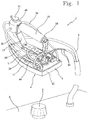
- an ironing system according to the present invention has been generally indicated with 1.
- the ironing system 1 comprises a boiler 2, necessary to produce water vapour, which withdraws the necessary water from a tank (not shown) integrated in the boiler 2 and accessible through a plug 3.
- the ironing system 1 further comprises an ironing plate 4 connected to the boiler 2 to dispense the produced vapour.
- the boiler 2 and the plate 4 are detached and distinct.
- a special hose 5 connects the boiler 2 to the plate 4 to bring the produced vapour to the latter.
- the plate 4 comprises a main body 6 which is manufactured, by way of example, by melting, and a lid 7 that can be placed over the main body 6.
- the plate 4 further comprises a bottom wall 8 having an outer surface 8a which defines an ironing surface 9 of the plate 4.
- the plate 4 bottom wall 8 has a plan essentially isoscele triangular shape with major sides which are rounded and confluent in a vertex 10 arranged at a front portion 4a of the plate 4.
- a minor side is opposed relative to the cited vertex 10 and is arranged at a rear portion 4b of the plate 4.
- the plate 4 comprises two side walls 11 connected to the bottom wall 8 and further convergent at the vertex 10 of the bottom wall 8.
- a rear wall 12 is connected to the side walls 11 and to the bottom wall 8 at the plate 4 rear portion 4b.
- the bottom wall 8, the side walls 11, and the rear wall 12 are formed in the plate 4 main body 6.
- the plate 4 further comprises a resistor 13 arranged inside the plate 4.
- the resistor 13 is symmetrically arranged on the bottom wall 8 relative to a middle plane "P" of the plate 4.
- the resistor 13 extends on the plate 4 bottom wall 8 along an essentially "U"-shaped path.
- Suitable electrical connectors 14 allow the electrical supply of the resistor 13.
- the cited electrical connectors 14 are arranged at the resistor 13 free ends in the rear plate 4 portion 4b.
- the supply is brought to the plate 4 thanks to an electric cable 15 associated to the hose 5.
- the resistor 13 heats the plate 4 in accordance with a predetermined temperature as selected by the user.
- Suitable control means allow selecting and keeping said predetermined temperature.
- the control means comprise a thermostat (not shown).
- the plate 4 is provided with a handle 16 to allow a user to manoeuvre the plate 4, thus allowing the ironing operation.
- the handle 16 is supported to the plate 4 by a bracket 17 rigidly connected to the same plate 4.
- a cover 18 made in thermo-insulating material wraps the handle 16 so as to avoid burns to the user and to increment the safety conditions of the ironing system 1.
- the plate 4 comprises a covering guard which is not illustrated in the annexed Figures.
- the ironing system comprises an overheating chamber 19 connected to the boiler 2 to increase the temperature of the vapour to be dispensed ( Fig. 4 ).
- the overheating chamber 19 is obtained in the plate 4.
- the overheating chamber 19 is obtained in the plate 4 main body 6 and is defined in cooperation with the lid 7.
- the overheating chamber 19 comprises an inlet connector 20 which allows the connection to a supply duct 21 which introduces the vapour coming from the boiler 2 in the same overheating chamber 19.
- the inlet connector 20 is obtained on the plate 4 lid 7.
- the overheating chamber 19 comprises a plurality of partition walls 22 which define a labyrinth-shaped path inside the same overheating chamber 19. In this manner, the vapour introduced in the overheating chamber 19 travels a long path 25 before being dispensed.
- the overheating chamber 19 is obtained in the proximity of the resistor 13.
- the plate 4 bottom wall 8 and the overheating chamber 19 partition walls 22 are heated, and the vapour, by licking very hot surfaces, increases its own temperature, as well as its own pressure and rate, getting overheated.
- the vapour is at a temperature ranging between 200°C and 220 °C.
- the labyrinth path imposed to the vapour by the overheating chamber 19 makes such overheating process quick and efficient.
- the overheating chamber 19 comprises a dispensing end portion 19a. Such end portion 19a is arranged in the proximity of the plate 4 front portion 4a.
- a plurality of dispensing nozzles 23 are obtained through the plate 4 bottom wall 8 to allow the ejection of the overheated vapour.
- the dispensing nozzles 23 are in fluidic communication with the overheating chamber 19.
- the nozzles 23 are in fluidic communication with the overheating chamber 19 end portion 19a.
- the cited dispensing nozzles 23 have a diameter which is constant and ranging between 1,5 and 3 mm. Preferably, the nozzles 23 diameter ranges between 2 and 2,5 mm.
- the dispensing nozzles 23 are arranged on the plate 4 in a "V"-configuration with the vertex facing the plate 4 front portion 4.
- the overheating chamber 19 end portion 19a is as well essentially "V"-shaped.
- the dispensing nozzles 23 are arranged according to different configurations, such as, for example, arched configurations.
- the nozzles 23 have respective development axes which are mutually parallel and orthogonal to the ironing surface 9.
- the dispensing nozzles 23 development axes have such a slope as to define an acute angle with the ironing surface 9.
- the nozzles 23 development axis is oriented so that the overheated vapour escapes being directed towards the plate 4 vertex 10.
- the escaped vapour interacts with a major, surface of the fabric to be ironed, making the ironing operation more efficient.
- the ironing system 1 further comprises an expansion chamber connected to the boiler 2, which is adapted to reduce at least the vapour temperature and pressure before it is dispensed.
- the expansion chamber 24 is arranged in fluidic communication with a dispensing chamber 25 to allow the passage and the dispensing of the cooled vapour in the expansion chamber 24.
- a plurality of through-holes 26 are formed in the plate 4 and arranged in direct fluidic communication with the dispensing chamber 25 to allow the escape of the cooled vapour.
- the holes 26 are obtained in the plate 4 bottom wall 8.
- the holes 26 have an increasing section from the dispensing chamber 25 towards the ironing surface 9. Such holes 26 have an average diameter ranging between 2 and 3,5 mm, preferably between 2,5 and 3 mm.
- expansion chamber 24 and the dispensing chamber 25 are distinct from the described overheating chamber 19. Similarly, the holes 26 are distinct from the dispensing nozzles 23.
- the dispensing chamber 25 is integrally obtained in the plate 4. More precisely, the dispensing chamber 25 is defined by its own defining walls 27 obtained in the plate 4 main body 6 and by the cited lid 7.
- the expansion chamber 24 is arranged outside the plate 4.
- the expansion chamber 24 is arranged above the plate 4.
- the expansion chamber 24 is rested to the plate 4 lid 7 by a plurality of feet 28 adapted to keep the expansion chamber 24 lifted from the lid 7 ( Fig. 5 and 6 ).
- the expansion chamber 24 being arranged outside the plate 4, the temperature thereof is below that of the rest of the plate 4.
- the feet 28 keep the expansion chamber 24 divided from the plate 4 lid 7, concurring to limit the expansion chamber 24 heating.
- the expansion chamber 24 is overlaid to the dispensing chamber 25 so as to allow a quick transfer from the expansion chamber 24 to the dispensing chamber 25 without the occurrence of significant changes in the characteristics of the cooled vapour.
- the expansion chamber 24 is directly connected to the dispensing chamber 25 by a passage port 29.
- the expansion chamber 24 comprises two mutually coupled shells 30.
- the ironing system 1 further comprises a pre-chamber 31 obtained inside the plate 4.
- a pre-chamber 31 is connected to the boiler 2 to receive the vapour from the latter, and is in fluidic communication with the expansion chamber 24 in order to introduce the vapour in the latter.
- the cited pre-chamber 31 advantageously prevents that water in liquid state is introduced into the expansion chamber 24.
- the pre-chamber 31 is obtained at the plate 4 rear portion 4b.
- the pre-chamber 31 is defined by the side walls 11 and the rear wall 12 of the plate 4, as well as by a dividing diaphragm 32 developing essentially parallel to the plate 4 rear wall 12.
- the pre-chamber 31 is arranged in the vicinity of the resistor 13, but is not arranged in direct contact with the latter. In other words, the pre-chamber 31 temperature is lower, relative to that of the zone which directly contacts the resistor 13.
- the pre-chamber 31 comprises an inlet coupling 33 to connect a supply tube 34 of the vapour coming from the boiler 2 and an outlet coupling 35 to connect the same pre-chamber 31 to the expansion chamber 24 via a suitable connection tube 36.
- the vapour coming from the boiler 2 is introduced in the pre-chamber 31.
- the latter being heated at least in part by the resistor 13, allows the vapour to keep a minimum temperature in order to avoid undesired condensations during the transfer of the same vapour from the pre-chamber 31 to the expansion chamber 24.
- the pre-chamber 31 allows intercepting optional water fractions---in liquid state coming from the boiler 2 Such water fractions, remaining inside the pre-chamber 31, can evaporate before being brought into the expansion chamber 24.
- the vapour When the vapour enters the expansion chamber 24, the volume which can be taken up by the same increases, consequently the vapour undergoes an expansion. Furthermore, the expansion chamber 24 being at a relatively low temperature, the vapour is also cooled. This lowers the vapour temperature and pressure. The vapour is then proximate to the condensation condition, due to the high humidity thereof. Typically, the second vapour is at a temperature ranging between 100°C and 110°C.
- a filter 37 occludes the passage port 29 so as to induce a further diffusion of the vapour.
- a gasket 38 is arranged at the filter 37 between the expansion chamber 24 and the dispensing chamber 25.
- the vapour expanded and cooled is ejected from the dispensing chamber 25 through the holes 26.
- the vapour is further expanded during the dispensing thereof.
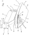
- the ironing system 1 further comprises first and second pluralities of dispensing ducts 39 arranged along two distinct rows on each side wall 11 of the plate 4 ( Fig. 4 and 7 ).
- the dispensing ducts 39 are arranged in the proximity of the plate 4 front portion 4a.
- the dispensing ducts 39 have an outlet section 39a arranged at a higher height than the ironing surface 9.
- the dispensing ducts 39 have respective development axes "A" which are inclined towards the ironing surface 9, so as to dispense the vapour towards the latter ( Fig. 8 ). In such a manner, the vapour dispensed by the dispensing ducts 39 licks the surface of a fabric to be ironed without passing through it.
- Each development axis "A” results to be inclined relative to the ironing surface 9. Such slope can advantageously be of an angle ranging between 25° and 55°, preferably between 35° and 45°.
- the dispensing ducts 39 development axes "A” are arranged preferably mutually parallel. Particularly, the development axes "A” are parallel to a middle plane “P" of the plate 4.
- the vapour flow dispensed by the dispensing ducts 39 is always directed to the direction of the plate 4 vertex 10, avoiding that the vapour flow may hit the user during the ironing operation.
- the plate 4 has recesses 40 respectively obtained on the side walls 11 of the same plate 4 ( Fig. 7 ).
- the dispensing ducts 39 are obtained at said recesses 40.
- the dispensing ducts 39 outlet sections 39a are arranged at the recesses 40.
- each recess 40 has a surface portion 40a, for example, planar or suitably shaped, which the dispensing ducts 39 are facing.
- each recess 40 are arranged essentially parallel to the ironing surface 9, but they could also be arranged inclined.
- the ironing system 1 further comprise a pair of side vapour chambers 41 to collect the vapour produced by the boiler 2 and to dispense it through the described dispensing ducts 39.
- the side vapour chambers 41 are obtained in the plate 4 in the proximity of the side walls 11.
- the side vapour chambers 41 are defined by a respective parting sheet 42 obtained in the plate 4 main body 6.
- Each side vapour chamber 41 comprises a collection portion 41 a in which the vapour coming from the boiler 2 enters, and a dispensing portion 41 b connected to the collection portion 41 a and directly in fluidic communication with the dispensing ducts 39.
- the collection portion 41a can be, for example, an individual one for the two side vapour chambers 41 and arranged at the tip plate, or can be double, and arranged on the plate sides, as in the illustrated example.
- a septum 43 is arranged between each collection portion 41a and the respective dispensing portion 41 b to partially divide the said portions.
- the septum 43 is obtained in the plate 4 main body 6 starting from the bottom wall 8. However, the septum 43 does not reach the plate 4 lid 7, in this manner leaving a passage port that allows the vapour passage from the collection portion 41a to the dispensing portion 41b, while preventing the passage of an optional fraction of liquid water. In fact, it remains entrapped by gravity in the collection portion 41a, until evaporation.
- each side vapour chamber 41 has an essentially linear inner shaping.
- the side vapour chambers 41 are so shaped as to define therein a labyrinth-shaped path to exert a overheating process on the vapour contained therein which is similar to that described in relation to the overheating chamber 19.
- Each side vapour chamber 41 is connected to the boiler through a connection duct 44 connected to respective connectors 45 of the same side vapour chambers 41.
- the ironing system 1 further comprises a deflector adapted to selectively direct the produced vapour coming from the boiler 2 at least to the dispensing ducts 39 and/or to the expansion chamber 24.
- the deflector 46 is adapted to selectively direct the vapour to the dispensing ducts 39 and/or to the expansion chamber 24 and/or to the overheating chamber 19.
- the deflector 46 is associated to the plate 4 at the above-described bracket 17.
- the deflector 46 comprises an inlet duct 47 to which the cited hose 5, coming from the boiler 2 and carrying therewith the vapour produced, is connected.
- the deflector 46 further comprises a first outlet duct 48 to which the supply duct 21 is connected in order to bring vapour to the overheating chamber 19, a second outlet duct 49 to which the supply tube 34 is connected in order to bring the vapour to the pre-chamber 31 and, successively, to the expansion chamber 24, and a third outlet duct 50 to which the connection duct 44 is connected in order to bring the vapour to the side vapour chamber 41.
- the deflector 46 also comprises a control handle 51 to select the vapour dispensing mode.
- the invention achieves the intended object and accomplishes important advantages.
- the vapour produced from the boiler 2 is expanded and cooled. Thereby, the vapour thus obtained and dispensed through the dispensing chamber 25 has a low outlet rate and a markedly higher humidity. In fact, in these conditions, the vapour is proximate to the condition of condensation.
- the vapour being dispensed from the holes 26 is capable of transferring heat to the fabric to be ironed in a much more effective manner.
- This characteristic is particularly applied when fabrics are ironed which are particularly strong and/or difficult to iron.
- the ironing system 1 according to the present invention it is possible to select different dispensing vapour modes. This makes the present ironing system 1 particularly flexible.
Landscapes
- Health & Medical Sciences (AREA)
- Public Health (AREA)
- Engineering & Computer Science (AREA)
- Textile Engineering (AREA)
- Irons (AREA)
Priority Applications (1)
| Application Number | Priority Date | Filing Date | Title |
|---|---|---|---|
| SI200831658A SI2072664T1 (sl) | 2007-12-19 | 2008-12-16 | Likalni sistem |
Applications Claiming Priority (1)
| Application Number | Priority Date | Filing Date | Title |
|---|---|---|---|
| ITBS20070201 ITBS20070201A1 (it) | 2007-12-19 | 2007-12-19 | Sistema stirante |
Publications (2)
| Publication Number | Publication Date |
|---|---|
| EP2072664A1 EP2072664A1 (en) | 2009-06-24 |
| EP2072664B1 true EP2072664B1 (en) | 2016-05-18 |
Family
ID=40315419
Family Applications (1)
| Application Number | Title | Priority Date | Filing Date |
|---|---|---|---|
| EP08171841.3A Not-in-force EP2072664B1 (en) | 2007-12-19 | 2008-12-16 | Ironing system |
Country Status (5)
| Country | Link |
|---|---|
| EP (1) | EP2072664B1 (it) |
| ES (1) | ES2587009T3 (it) |
| IT (1) | ITBS20070201A1 (it) |
| PT (1) | PT2072664T (it) |
| SI (1) | SI2072664T1 (it) |
Family Cites Families (3)
| Publication number | Priority date | Publication date | Assignee | Title |
|---|---|---|---|---|
| BE542441A (it) * | 1955-11-15 | |||
| IT8423859V0 (it) * | 1984-11-22 | 1984-11-22 | Macchi Ercole | Struttura di gruppo valvolare per ferri da stiro a vapore. |
| JP3048520B2 (ja) * | 1996-04-05 | 2000-06-05 | 直本工業株式会社 | 業務用アイロン |
-
2007
- 2007-12-19 IT ITBS20070201 patent/ITBS20070201A1/it unknown
-
2008
- 2008-12-16 EP EP08171841.3A patent/EP2072664B1/en not_active Not-in-force
- 2008-12-16 SI SI200831658A patent/SI2072664T1/sl unknown
- 2008-12-16 PT PT81718413T patent/PT2072664T/pt unknown
- 2008-12-16 ES ES08171841.3T patent/ES2587009T3/es active Active
Also Published As
| Publication number | Publication date |
|---|---|
| ES2587009T3 (es) | 2016-10-20 |
| PT2072664T (pt) | 2016-08-08 |
| ITBS20070201A1 (it) | 2009-06-20 |
| SI2072664T1 (sl) | 2016-09-30 |
| EP2072664A1 (en) | 2009-06-24 |
Similar Documents
| Publication | Publication Date | Title |
|---|---|---|
| CN107429475B (zh) | 具有水垢收集室的手持式蒸汽挂烫机 | |
| EP2941502B1 (en) | A garment steaming device | |
| CN208151736U (zh) | 蒸汽熨烫设备 | |
| RU2646184C2 (ru) | Паровой гладильный аппарат, содержащий утюг | |
| US20040025382A1 (en) | Iron with surge steam function | |
| CN106923653A (zh) | 蒸汽烹饪装置 | |
| US12173448B2 (en) | Hybrid steamer iron assembly | |
| CN102995375B (zh) | 包括蒸汽分配回路的熨烫设备 | |
| EP2072662B1 (en) | Ironing system | |
| CN107587337B (zh) | 包括与熨烫板热接触的加热体的熨斗 | |
| RU2643972C2 (ru) | Паровой гладильный аппарат | |
| EP2098629B1 (en) | Ironing system | |
| EP2072664B1 (en) | Ironing system | |
| CN207428944U (zh) | 蒸汽烹饪装置 | |
| CN114729498A (zh) | 用于蒸汽熨烫设备的板及相应的制造方法 | |
| KR200425391Y1 (ko) | 오버히트 방지부가 구비된 스팀 발생기 | |
| CN108611834B (zh) | 包括通过导管彼此连接的蒸汽发生基部和熨斗的蒸汽熨烫设备 | |
| CN105484002B (zh) | 蒸汽式熨烫设备 | |
| EP2138628A1 (en) | Steam iron with water preheating device | |
| CN108611833B (zh) | 包括熨烫表面,加热底板和蒸发室的熨斗 | |
| CN210420656U (zh) | 熨烫装置 | |
| CN115478423A (zh) | 包括包围蒸汽导管的手柄的便携式熨烫设备 | |
| EP3118369A1 (en) | Improved iron structure | |
| US12286744B2 (en) | Domestic appliance for ironing and/or steaming comprising at least two vaporization chambers connected to each other by a connecting duct | |
| CN221297361U (zh) | 一种汽烫独立控温的挂烫机 |
Legal Events
| Date | Code | Title | Description |
|---|---|---|---|
| PUAI | Public reference made under article 153(3) epc to a published international application that has entered the european phase |
Free format text: ORIGINAL CODE: 0009012 |
|
| AK | Designated contracting states |
Kind code of ref document: A1 Designated state(s): AT BE BG CH CY CZ DE DK EE ES FI FR GB GR HR HU IE IS IT LI LT LU LV MC MT NL NO PL PT RO SE SI SK TR |
|
| AX | Request for extension of the european patent |
Extension state: AL BA MK RS |
|
| 17P | Request for examination filed |
Effective date: 20090923 |
|
| 17Q | First examination report despatched |
Effective date: 20091022 |
|
| AKX | Designation fees paid |
Designated state(s): AT BE BG CH CY CZ DE DK EE ES FI FR GB GR HR HU IE IS IT LI LT LU LV MC MT NL NO PL PT RO SE SI SK TR |
|
| RAP1 | Party data changed (applicant data changed or rights of an application transferred) |
Owner name: CANDY HOOVER GROUP S.R.L. |
|
| GRAP | Despatch of communication of intention to grant a patent |
Free format text: ORIGINAL CODE: EPIDOSNIGR1 |
|
| INTG | Intention to grant announced |
Effective date: 20160107 |
|
| GRAS | Grant fee paid |
Free format text: ORIGINAL CODE: EPIDOSNIGR3 |
|
| GRAA | (expected) grant |
Free format text: ORIGINAL CODE: 0009210 |
|
| AK | Designated contracting states |
Kind code of ref document: B1 Designated state(s): AT BE BG CH CY CZ DE DK EE ES FI FR GB GR HR HU IE IS IT LI LT LU LV MC MT NL NO PL PT RO SE SI SK TR |
|
| REG | Reference to a national code |
Ref country code: GB Ref legal event code: FG4D |
|
| REG | Reference to a national code |
Ref country code: CH Ref legal event code: EP |
|
| REG | Reference to a national code |
Ref country code: IE Ref legal event code: FG4D Ref country code: AT Ref legal event code: REF Ref document number: 800577 Country of ref document: AT Kind code of ref document: T Effective date: 20160615 |
|
| REG | Reference to a national code |
Ref country code: DE Ref legal event code: R096 Ref document number: 602008044288 Country of ref document: DE |
|
| REG | Reference to a national code |
Ref country code: PT Ref legal event code: SC4A Ref document number: 2072664 Country of ref document: PT Date of ref document: 20160808 Kind code of ref document: T Free format text: AVAILABILITY OF NATIONAL TRANSLATION Effective date: 20160802 |
|
| REG | Reference to a national code |
Ref country code: CH Ref legal event code: NV Representative=s name: JACOBACCI AND PARTNERS SA, CH |
|
| REG | Reference to a national code |
Ref country code: NL Ref legal event code: MP Effective date: 20160518 |
|
| REG | Reference to a national code |
Ref country code: LT Ref legal event code: MG4D |
|
| REG | Reference to a national code |
Ref country code: ES Ref legal event code: FG2A Ref document number: 2587009 Country of ref document: ES Kind code of ref document: T3 Effective date: 20161020 |
|
| PG25 | Lapsed in a contracting state [announced via postgrant information from national office to epo] |
Ref country code: NO Free format text: LAPSE BECAUSE OF FAILURE TO SUBMIT A TRANSLATION OF THE DESCRIPTION OR TO PAY THE FEE WITHIN THE PRESCRIBED TIME-LIMIT Effective date: 20160818 Ref country code: NL Free format text: LAPSE BECAUSE OF FAILURE TO SUBMIT A TRANSLATION OF THE DESCRIPTION OR TO PAY THE FEE WITHIN THE PRESCRIBED TIME-LIMIT Effective date: 20160518 Ref country code: FI Free format text: LAPSE BECAUSE OF FAILURE TO SUBMIT A TRANSLATION OF THE DESCRIPTION OR TO PAY THE FEE WITHIN THE PRESCRIBED TIME-LIMIT Effective date: 20160518 Ref country code: LT Free format text: LAPSE BECAUSE OF FAILURE TO SUBMIT A TRANSLATION OF THE DESCRIPTION OR TO PAY THE FEE WITHIN THE PRESCRIBED TIME-LIMIT Effective date: 20160518 |
|
| PG25 | Lapsed in a contracting state [announced via postgrant information from national office to epo] |
Ref country code: SE Free format text: LAPSE BECAUSE OF FAILURE TO SUBMIT A TRANSLATION OF THE DESCRIPTION OR TO PAY THE FEE WITHIN THE PRESCRIBED TIME-LIMIT Effective date: 20160518 Ref country code: LV Free format text: LAPSE BECAUSE OF FAILURE TO SUBMIT A TRANSLATION OF THE DESCRIPTION OR TO PAY THE FEE WITHIN THE PRESCRIBED TIME-LIMIT Effective date: 20160518 Ref country code: GR Free format text: LAPSE BECAUSE OF FAILURE TO SUBMIT A TRANSLATION OF THE DESCRIPTION OR TO PAY THE FEE WITHIN THE PRESCRIBED TIME-LIMIT Effective date: 20160819 |
|
| REG | Reference to a national code |
Ref country code: FR Ref legal event code: PLFP Year of fee payment: 9 |
|
| PG25 | Lapsed in a contracting state [announced via postgrant information from national office to epo] |
Ref country code: SK Free format text: LAPSE BECAUSE OF FAILURE TO SUBMIT A TRANSLATION OF THE DESCRIPTION OR TO PAY THE FEE WITHIN THE PRESCRIBED TIME-LIMIT Effective date: 20160518 Ref country code: CZ Free format text: LAPSE BECAUSE OF FAILURE TO SUBMIT A TRANSLATION OF THE DESCRIPTION OR TO PAY THE FEE WITHIN THE PRESCRIBED TIME-LIMIT Effective date: 20160518 Ref country code: DK Free format text: LAPSE BECAUSE OF FAILURE TO SUBMIT A TRANSLATION OF THE DESCRIPTION OR TO PAY THE FEE WITHIN THE PRESCRIBED TIME-LIMIT Effective date: 20160518 Ref country code: EE Free format text: LAPSE BECAUSE OF FAILURE TO SUBMIT A TRANSLATION OF THE DESCRIPTION OR TO PAY THE FEE WITHIN THE PRESCRIBED TIME-LIMIT Effective date: 20160518 Ref country code: RO Free format text: LAPSE BECAUSE OF FAILURE TO SUBMIT A TRANSLATION OF THE DESCRIPTION OR TO PAY THE FEE WITHIN THE PRESCRIBED TIME-LIMIT Effective date: 20160518 |
|
| PGFP | Annual fee paid to national office [announced via postgrant information from national office to epo] |
Ref country code: GB Payment date: 20161222 Year of fee payment: 9 |
|
| REG | Reference to a national code |
Ref country code: DE Ref legal event code: R097 Ref document number: 602008044288 Country of ref document: DE |
|
| PG25 | Lapsed in a contracting state [announced via postgrant information from national office to epo] |
Ref country code: PL Free format text: LAPSE BECAUSE OF FAILURE TO SUBMIT A TRANSLATION OF THE DESCRIPTION OR TO PAY THE FEE WITHIN THE PRESCRIBED TIME-LIMIT Effective date: 20160518 |
|
| PGFP | Annual fee paid to national office [announced via postgrant information from national office to epo] |
Ref country code: FR Payment date: 20161229 Year of fee payment: 9 Ref country code: IT Payment date: 20161206 Year of fee payment: 9 |
|
| PLBE | No opposition filed within time limit |
Free format text: ORIGINAL CODE: 0009261 |
|
| STAA | Information on the status of an ep patent application or granted ep patent |
Free format text: STATUS: NO OPPOSITION FILED WITHIN TIME LIMIT |
|
| 26N | No opposition filed |
Effective date: 20170221 |
|
| PGFP | Annual fee paid to national office [announced via postgrant information from national office to epo] |
Ref country code: DE Payment date: 20170228 Year of fee payment: 9 |
|
| PG25 | Lapsed in a contracting state [announced via postgrant information from national office to epo] |
Ref country code: BE Free format text: LAPSE BECAUSE OF NON-PAYMENT OF DUE FEES Effective date: 20161231 |
|
| PG25 | Lapsed in a contracting state [announced via postgrant information from national office to epo] |
Ref country code: MC Free format text: LAPSE BECAUSE OF FAILURE TO SUBMIT A TRANSLATION OF THE DESCRIPTION OR TO PAY THE FEE WITHIN THE PRESCRIBED TIME-LIMIT Effective date: 20160518 |
|
| REG | Reference to a national code |
Ref country code: CH Ref legal event code: PL |
|
| REG | Reference to a national code |
Ref country code: SI Ref legal event code: KO00 Effective date: 20170818 |
|
| REG | Reference to a national code |
Ref country code: IE Ref legal event code: MM4A |
|
| PG25 | Lapsed in a contracting state [announced via postgrant information from national office to epo] |
Ref country code: LU Free format text: LAPSE BECAUSE OF NON-PAYMENT OF DUE FEES Effective date: 20161216 Ref country code: CH Free format text: LAPSE BECAUSE OF NON-PAYMENT OF DUE FEES Effective date: 20161231 Ref country code: LI Free format text: LAPSE BECAUSE OF NON-PAYMENT OF DUE FEES Effective date: 20161231 |
|
| PG25 | Lapsed in a contracting state [announced via postgrant information from national office to epo] |
Ref country code: PT Free format text: LAPSE BECAUSE OF NON-PAYMENT OF DUE FEES Effective date: 20170918 Ref country code: IE Free format text: LAPSE BECAUSE OF NON-PAYMENT OF DUE FEES Effective date: 20161216 Ref country code: SI Free format text: LAPSE BECAUSE OF NON-PAYMENT OF DUE FEES Effective date: 20161217 |
|
| REG | Reference to a national code |
Ref country code: BE Ref legal event code: FP Effective date: 20160812 Ref country code: BE Ref legal event code: MM Effective date: 20161231 |
|
| REG | Reference to a national code |
Ref country code: AT Ref legal event code: MM01 Ref document number: 800577 Country of ref document: AT Kind code of ref document: T Effective date: 20161216 |
|
| PG25 | Lapsed in a contracting state [announced via postgrant information from national office to epo] |
Ref country code: HU Free format text: LAPSE BECAUSE OF FAILURE TO SUBMIT A TRANSLATION OF THE DESCRIPTION OR TO PAY THE FEE WITHIN THE PRESCRIBED TIME-LIMIT; INVALID AB INITIO Effective date: 20081216 Ref country code: CY Free format text: LAPSE BECAUSE OF FAILURE TO SUBMIT A TRANSLATION OF THE DESCRIPTION OR TO PAY THE FEE WITHIN THE PRESCRIBED TIME-LIMIT Effective date: 20160518 Ref country code: ES Free format text: LAPSE BECAUSE OF NON-PAYMENT OF DUE FEES Effective date: 20171217 Ref country code: AT Free format text: LAPSE BECAUSE OF NON-PAYMENT OF DUE FEES Effective date: 20161216 |
|
| REG | Reference to a national code |
Ref country code: ES Ref legal event code: FD2A Effective date: 20180622 |
|
| PG25 | Lapsed in a contracting state [announced via postgrant information from national office to epo] |
Ref country code: TR Free format text: LAPSE BECAUSE OF FAILURE TO SUBMIT A TRANSLATION OF THE DESCRIPTION OR TO PAY THE FEE WITHIN THE PRESCRIBED TIME-LIMIT Effective date: 20160518 Ref country code: HR Free format text: LAPSE BECAUSE OF FAILURE TO SUBMIT A TRANSLATION OF THE DESCRIPTION OR TO PAY THE FEE WITHIN THE PRESCRIBED TIME-LIMIT Effective date: 20160518 Ref country code: IS Free format text: LAPSE BECAUSE OF FAILURE TO SUBMIT A TRANSLATION OF THE DESCRIPTION OR TO PAY THE FEE WITHIN THE PRESCRIBED TIME-LIMIT Effective date: 20160518 |
|
| REG | Reference to a national code |
Ref country code: DE Ref legal event code: R119 Ref document number: 602008044288 Country of ref document: DE |
|
| PG25 | Lapsed in a contracting state [announced via postgrant information from national office to epo] |
Ref country code: ES Free format text: LAPSE BECAUSE OF NON-PAYMENT OF DUE FEES Effective date: 20161217 Ref country code: BG Free format text: LAPSE BECAUSE OF FAILURE TO SUBMIT A TRANSLATION OF THE DESCRIPTION OR TO PAY THE FEE WITHIN THE PRESCRIBED TIME-LIMIT Effective date: 20160518 |
|
| GBPC | Gb: european patent ceased through non-payment of renewal fee |
Effective date: 20171216 |
|
| PG25 | Lapsed in a contracting state [announced via postgrant information from national office to epo] |
Ref country code: MT Free format text: LAPSE BECAUSE OF NON-PAYMENT OF DUE FEES Effective date: 20161216 |
|
| REG | Reference to a national code |
Ref country code: FR Ref legal event code: ST Effective date: 20180831 |
|
| PG25 | Lapsed in a contracting state [announced via postgrant information from national office to epo] |
Ref country code: IT Free format text: LAPSE BECAUSE OF NON-PAYMENT OF DUE FEES Effective date: 20171216 Ref country code: FR Free format text: LAPSE BECAUSE OF NON-PAYMENT OF DUE FEES Effective date: 20180102 Ref country code: DE Free format text: LAPSE BECAUSE OF NON-PAYMENT OF DUE FEES Effective date: 20180703 |
|
| PG25 | Lapsed in a contracting state [announced via postgrant information from national office to epo] |
Ref country code: GB Free format text: LAPSE BECAUSE OF NON-PAYMENT OF DUE FEES Effective date: 20171216 |
|
| REG | Reference to a national code |
Ref country code: AT Ref legal event code: UEP Ref document number: 800577 Country of ref document: AT Kind code of ref document: T Effective date: 20160518 |