EP2072689A2 - Unterirdische Kammern - Google Patents
Unterirdische Kammern Download PDFInfo
- Publication number
- EP2072689A2 EP2072689A2 EP08254051A EP08254051A EP2072689A2 EP 2072689 A2 EP2072689 A2 EP 2072689A2 EP 08254051 A EP08254051 A EP 08254051A EP 08254051 A EP08254051 A EP 08254051A EP 2072689 A2 EP2072689 A2 EP 2072689A2
- Authority
- EP
- European Patent Office
- Prior art keywords
- chamber
- chamber element
- elements
- adjacent
- abutment face
- Prior art date
- Legal status (The legal status is an assumption and is not a legal conclusion. Google has not performed a legal analysis and makes no representation as to the accuracy of the status listed.)
- Withdrawn
Links
- 230000015572 biosynthetic process Effects 0.000 claims abstract description 16
- 238000007373 indentation Methods 0.000 claims description 12
- 230000000295 complement effect Effects 0.000 claims description 6
- 239000000945 filler Substances 0.000 claims description 5
- 239000003365 glass fiber Substances 0.000 claims description 5
- 229920001187 thermosetting polymer Polymers 0.000 claims description 5
- 230000000284 resting effect Effects 0.000 claims description 4
- 239000000835 fiber Substances 0.000 claims description 3
- 230000002787 reinforcement Effects 0.000 claims description 3
- 229920005989 resin Polymers 0.000 claims description 3
- 239000011347 resin Substances 0.000 claims description 3
- 239000011208 reinforced composite material Substances 0.000 claims description 2
- 238000005755 formation reaction Methods 0.000 description 9
- 239000000463 material Substances 0.000 description 9
- 238000009434 installation Methods 0.000 description 3
- 239000004570 mortar (masonry) Substances 0.000 description 3
- 239000000654 additive Substances 0.000 description 2
- 238000010276 construction Methods 0.000 description 2
- 239000011474 engineering brick Substances 0.000 description 2
- 239000000203 mixture Substances 0.000 description 2
- 229920001225 polyester resin Polymers 0.000 description 2
- 239000004645 polyester resin Substances 0.000 description 2
- 229910000831 Steel Inorganic materials 0.000 description 1
- 239000011449 brick Substances 0.000 description 1
- 239000003795 chemical substances by application Substances 0.000 description 1
- 150000001875 compounds Chemical class 0.000 description 1
- 239000004567 concrete Substances 0.000 description 1
- 238000009472 formulation Methods 0.000 description 1
- 238000011065 in-situ storage Methods 0.000 description 1
- 239000004615 ingredient Substances 0.000 description 1
- 239000003999 initiator Substances 0.000 description 1
- 239000002184 metal Substances 0.000 description 1
- 238000000034 method Methods 0.000 description 1
- 238000012986 modification Methods 0.000 description 1
- 230000004048 modification Effects 0.000 description 1
- 238000000465 moulding Methods 0.000 description 1
- 239000000049 pigment Substances 0.000 description 1
- 239000002574 poison Substances 0.000 description 1
- 231100000614 poison Toxicity 0.000 description 1
- 239000002994 raw material Substances 0.000 description 1
- 239000003381 stabilizer Substances 0.000 description 1
- 239000010959 steel Substances 0.000 description 1
- 239000002562 thickening agent Substances 0.000 description 1
- XLYOFNOQVPJJNP-UHFFFAOYSA-N water Substances O XLYOFNOQVPJJNP-UHFFFAOYSA-N 0.000 description 1
Images
Classifications
-
- E—FIXED CONSTRUCTIONS
- E02—HYDRAULIC ENGINEERING; FOUNDATIONS; SOIL SHIFTING
- E02D—FOUNDATIONS; EXCAVATIONS; EMBANKMENTS; UNDERGROUND OR UNDERWATER STRUCTURES
- E02D29/00—Independent underground or underwater structures; Retaining walls
- E02D29/12—Manhole shafts; Other inspection or access chambers; Accessories therefor
-
- E—FIXED CONSTRUCTIONS
- E02—HYDRAULIC ENGINEERING; FOUNDATIONS; SOIL SHIFTING
- E02D—FOUNDATIONS; EXCAVATIONS; EMBANKMENTS; UNDERGROUND OR UNDERWATER STRUCTURES
- E02D29/00—Independent underground or underwater structures; Retaining walls
- E02D29/12—Manhole shafts; Other inspection or access chambers; Accessories therefor
- E02D29/121—Manhole shafts; Other inspection or access chambers; Accessories therefor characterised by the connection between shaft elements, e.g. of rings forming said shaft
-
- E—FIXED CONSTRUCTIONS
- E02—HYDRAULIC ENGINEERING; FOUNDATIONS; SOIL SHIFTING
- E02D—FOUNDATIONS; EXCAVATIONS; EMBANKMENTS; UNDERGROUND OR UNDERWATER STRUCTURES
- E02D29/00—Independent underground or underwater structures; Retaining walls
- E02D29/12—Manhole shafts; Other inspection or access chambers; Accessories therefor
- E02D29/14—Covers for manholes or the like; Frames for covers
-
- E—FIXED CONSTRUCTIONS
- E02—HYDRAULIC ENGINEERING; FOUNDATIONS; SOIL SHIFTING
- E02D—FOUNDATIONS; EXCAVATIONS; EMBANKMENTS; UNDERGROUND OR UNDERWATER STRUCTURES
- E02D29/00—Independent underground or underwater structures; Retaining walls
- E02D29/12—Manhole shafts; Other inspection or access chambers; Accessories therefor
- E02D29/14—Covers for manholes or the like; Frames for covers
- E02D29/1427—Locking devices
-
- E—FIXED CONSTRUCTIONS
- E02—HYDRAULIC ENGINEERING; FOUNDATIONS; SOIL SHIFTING
- E02D—FOUNDATIONS; EXCAVATIONS; EMBANKMENTS; UNDERGROUND OR UNDERWATER STRUCTURES
- E02D29/00—Independent underground or underwater structures; Retaining walls
- E02D29/12—Manhole shafts; Other inspection or access chambers; Accessories therefor
- E02D29/14—Covers for manholes or the like; Frames for covers
- E02D29/1454—Non-circular covers, e.g. hexagonal, elliptic
-
- E—FIXED CONSTRUCTIONS
- E02—HYDRAULIC ENGINEERING; FOUNDATIONS; SOIL SHIFTING
- E02D—FOUNDATIONS; EXCAVATIONS; EMBANKMENTS; UNDERGROUND OR UNDERWATER STRUCTURES
- E02D29/00—Independent underground or underwater structures; Retaining walls
- E02D29/16—Arrangement or construction of joints in foundation structures
-
- E—FIXED CONSTRUCTIONS
- E03—WATER SUPPLY; SEWERAGE
- E03F—SEWERS; CESSPOOLS
- E03F5/00—Sewerage structures
- E03F5/02—Manhole shafts or other inspection chambers; Snow-filling openings; accessories
-
- E—FIXED CONSTRUCTIONS
- E03—WATER SUPPLY; SEWERAGE
- E03F—SEWERS; CESSPOOLS
- E03F5/00—Sewerage structures
- E03F5/02—Manhole shafts or other inspection chambers; Snow-filling openings; accessories
- E03F5/022—Partitioned to allow more than one medium to flow through
-
- H—ELECTRICITY
- H02—GENERATION; CONVERSION OR DISTRIBUTION OF ELECTRIC POWER
- H02G—INSTALLATION OF ELECTRIC CABLES OR LINES, OR OF COMBINED OPTICAL AND ELECTRIC CABLES OR LINES
- H02G9/00—Installations of electric cables or lines in or on the ground or water
- H02G9/10—Installations of electric cables or lines in or on the ground or water in cable chambers, e.g. in manhole or in handhole
Definitions
- This invention relates to underground chambers, and to champer elements for use in constructing underground chambers.
- Underground chambers are used to house installations such as various diameter pipes, fittings and accessories, conduits, ducting, all types of cabling, meter/junction boxes, valves and associated fixtures and fittings.
- Such chambers are typically constructed from engineering bricks.
- Engineering bricks are not particularly strong and, because the mortar is mixed by hand and the bricks are laid manually, the construction is time-consuming and expensive and the quality of the installation can be inconsistent. It is also known to use preformed concrete sections for underground chambers but these are unwieldy and difficult to handle, as well as being relatively brittle.
- a chamber element for use in constructing an underground chamber, the element comprising an elongate body having an abutment face at an end thereof, for abutting against a face of an adjacent chamber element to make up the chamber or a part of the chamber, the abutment face being angled at about 45° to the length of the chamber element such that when two cooperating chamber elements are placed with their respective abutment faces adjacent to and in contact with one another, the chamber elements lie at 90° to one another, an inner step being provided on the chamber element spaced below the top thereof, the step being configured to be able to receive in respective configurations either one of a formation on a similar chamber element mounted on top of the chamber element, or an edge of a cover member.
- An engagement formation may be provided on the underside of the chamber element which formation is engageable with the inner step of a chamber element located therebeneath.
- the engagement formation may be configured such that when engaging with the inner step of a chamber element located therebeneath, the underside of the top chamber element sits substantially flat on top of the lower chamber element.
- the chamber element preferably includes a locking formation for receiving a locking member, which locking member is selectively engageable with a cover member to retain same on the chamber element.
- the locking formation preferably includes a recess which can receive part of a locking member. The recess may be located adjacent the abutment face.
- the recess may be configured such that a locking member can extend between recesses in two cooperating chamber elements across the angle between the two cooperating chamber elements.
- the recess may be configured such that a locking member can extend therefrom substantially perpendicular to the adjacent abutment face.
- the abutment face of the chamber element made include means for resisting sliding movement relative to the adjacent abutment face of a cooperating chamber element, the means including a projection and/or an indentation for engaging a complementary indentation and/or projection on the face of the adjacent chamber element.
- the face includes a projection and an indentation, for engaging a complementary indentation and projection on the adjacent face.
- the projection may be in the form of an elongate rib, which may be generally triangular in section, with the indentation being of complementary shape.
- the abutment face is generally planar, apart from the projection/indentation.
- the chamber element is generally hollow, having one open elongate side.
- the open side is located on a side of the chamber element which will form an external side of the resulting chamber.
- the chamber element comprises a top wall and a side wall substantially perpendicular to the top wall.
- the abutment face is preferably perpendicular to the top wall and may be angled, preferably at 135°, to the side wall.
- the chamber element includes a plurality of ribs which extend from the top and side wall, preferably perpendicular to the top and side wall.
- the ribs may span substantially an entire width of the top wall.
- the chamber element is shaped such that four abutting chamber elements may form four or more sides of a generally rectangular chamber layer.
- the chamber element is shaped such that a plurality of chamber layers may be stacked one on top of another.
- the chamber element comprises a fibre reinforced composite material, preferably consisting primarily of a thermosetting resin, a glass fibre reinforcement and a filler.
- the material may include between 15 and 50% glass fibre, with fibre lengths being between 12 mm and 50 mm.
- the material may include between 15 and 30 weight % of thermosetting polyester resin, between 15 and 50 weight % filler and 3 and 10 weight % of other materials.
- the material of the chamber element has a tensile strength of between 65 and 80 MPa and a tensile modulus of between 8.5 and 12.5 GPa.
- kit of parts for use in constructing an underground chamber including a plurality of chamber elements according to any of the preceding definitions.
- the kit may further include a plurality of junction elements for joining adjacent chamber elements end-to-end, such that the chamber elements are aligned.
- the kit may include a cover member, which cover member is locatable resting on the inner step of the chamber elements.
- the cover member may be configured such that when resting on the inner step of the chamber elements, the top of the cover member is substantially flush with the top of the chamber elements.
- the kit may include a locking member locatable in recesses in the chamber elements, the locking member being selectively engageable with the cover member to lock same in a closed position.
- Two locking members may be provided.
- an underground chamber comprising a plurality of chamber elements according to any of the preceding definitions, the chamber elements being assembled with their abutment faces adjacent to and abutting one another.
- the chamber may include a cover member as defined above.
- a locking member as defined above may be provided located in respective recesses in the chamber element to selectively lock the cover member in a closed position. Two locking members may be provided.
- the underground chamber may comprise a plurality of chamber layers one on top of another, each chamber layer comprising at least four chamber elements in abutment with one another and arranged to form a rectangle.
- the or each locking member may be provided in the top chamber layer only.
- the locking member may be in the form of a strip of material with a hole therethrough to receive a member extending from the cover member.
- the locking member may be made of metal.
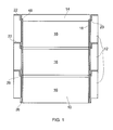
- Fig. 1 shows an underground chamber 10 for installation underground to house utilities such as gas and water meters, valves or stopcocks etc.
- the chamber 10 is formed from a number of chamber elements 12 which together define a hollow arrangement within which the underground utility can be located.
- a cover 14 closes the top of the chamber 10.
- the chamber 10 is formed of three square chamber layers 16, each formed from four identical chamber elements 12. Typically the elements could have a length of between 0.5m and 1.5m.
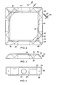
- Each element 12 has an inner wall 18 with an outward step 20 towards the top thereof leading to a top wall 22.
- each element 12 ends with an inclined end wall 24 at a 45° inclination to the inner wall 18, the end wall 24 defining an abutment face.
- the end walls 24 are both inclined outwardly from the inner wall 18.
- the lower end of the inner wall 18 is turned outwardly to define a flange 26, of a size to locate on the step 20.
- a pair of vertically extending ribs 28 are provided extending outwardly from the inner wall 18 and connected to the top wall 22.
- the ribs 28 and outer parts of the end walls 24 terminate above the flange 26 for a distance corresponding substantially to the distance between the step 20 and top wall 22.
- Fixing holes 30 are provided through each of the inclined end walls 24.
- An opening 32 is provided through the inner wall 18 between the ribs 28.
- the recesses 34 on adjacent chamber elements 12 as shown in Fig. 2 define a rectangular recess 38 facing into the chamber 10 at each corner, extending at 45° to the inner walls 18.
- two of the opposite rectangular recesses 38 in the top most layer 16 locate a locking member 40 in the form of a steel strip with a central hole 42 therein.
- Each end wall 24 includes formations to prevent sliding movement adjacent chamber elements 12.
- the formations include a V-shaped projection 44 and corresponding slot 46 on each end wall 24, located opposite corresponding projections 44 and slots 46 on the end wall 24 of an adjacent chamber element 12.
- the cover 14 is of a size to substantially close the top of the chamber 10, and has an inner step 48 which locates against the step 20 on the top layer 16, such that the top of the cover 14 is substantially flush with the top wall 22 of the top most layer 16.
- Locking means are provided (not shown) in the form of elongate members which extend below the cover 14 and are slectively lockably engageable with the holes 42 to lock the cover 14 on the chamber elements 12.
- the locking means may be rotatable by an appropriate tool in a conventional manner, and this feature is not therefore further described.
- the four chamber elements 12 are formed into each layer 16.
- a bolt 50 with a nut 52 and washers 54 is provided at each corner extending through the respective fixing holes 30 to retain the chamber elements 12 together.
- Each layer 16 is located on a layer below, with the flanges 26 engaging on the steps 20.
- the locking members 40 are only provided on this layer 26, and permit the cover 14 to be selectively locked in position.
- the cover 14 fits with the cover step 48 located on the respective steps 20.
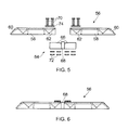
- Figs. 5 and 6 show an alternative arrangement where longer chamber elements 56 can be formed.
- the chamber elements 56 include two end parts 58.
- Each end part 58 has one end wall 60 which is similar to the end wall 24.
- a channel 62 is provided which can locate a joining member 64.
- the joining member 64 has two end parts 66 which are slidably locatable in respective channels on two end parts 58, and a central part 68 of a similar cross sectional size to the chamber elements 12.
- the end parts 66 can be mounted in the channels 62 by bolts 70 engaging with nuts 72 and washers 74. With such an arrangement chamber elements of any required size can be produced with appropriate length components.
- the chamber elements and/or cover may be made from SMC (sheet moulded compound) which consists primarily of a thermosetting resin, glass fibre reinforcements and filler. Additional ingredients may also include low profile additives to modify any potential component distortion or shrinkage, cure initiators, thickeners, process additives and mould release agents to enhance processing/moulding of the material together with pigment stabilisers to affect appearance and weatherability.
- SMC sheet moulded compound
- a typical composition for the material is as follows: Raw Material % Weight % Volume Thermosetting Polyester resin 15-30 30-45 Glass Fibre 15-50 10-40 Filler 15-50 10-40 All other 3-10 5-15
- the properties of the material are preferably as follows: SMC Material Formulation ⁇ 25% GF Mechanical Properties Tensile Strength 65-80 Mpa Tensile Modulus 8.5-12.5 Gpa Tensile Failure Strain 1.30% Flexural Strength 155-200 Mpa Flex Modulus 8.5-14 Mpa Compressive Strength 183 Mpa Compressive Modulus 11.7 Gpa Poisons Ration 0.25 Coefficient of Thermal Expansion 14-18 x 10E-6/K SG 1.85-2.00
- the construction of the chamber elements means that no separate frame is required to mount the cover, and accordingly only a small number of different components are required, thereby providing cost savings.
- the chamber elements can be embedded in mortar, which mortar would engage on the outside of the chamber elements to provide strong keying thereof.
Landscapes
- Engineering & Computer Science (AREA)
- Life Sciences & Earth Sciences (AREA)
- Structural Engineering (AREA)
- General Life Sciences & Earth Sciences (AREA)
- Mining & Mineral Resources (AREA)
- Paleontology (AREA)
- Civil Engineering (AREA)
- General Engineering & Computer Science (AREA)
- Environmental & Geological Engineering (AREA)
- Health & Medical Sciences (AREA)
- Hydrology & Water Resources (AREA)
- Public Health (AREA)
- Water Supply & Treatment (AREA)
- Buildings Adapted To Withstand Abnormal External Influences (AREA)
- Sewage (AREA)
- Piles And Underground Anchors (AREA)
- Underground Structures, Protecting, Testing And Restoring Foundations (AREA)
Applications Claiming Priority (1)
| Application Number | Priority Date | Filing Date | Title |
|---|---|---|---|
| GB0725016.0A GB2455788B (en) | 2007-12-21 | 2007-12-21 | Underground chambers |
Publications (2)
| Publication Number | Publication Date |
|---|---|
| EP2072689A2 true EP2072689A2 (de) | 2009-06-24 |
| EP2072689A3 EP2072689A3 (de) | 2013-08-21 |
Family
ID=39048584
Family Applications (1)
| Application Number | Title | Priority Date | Filing Date |
|---|---|---|---|
| EP08254051.9A Withdrawn EP2072689A3 (de) | 2007-12-21 | 2008-12-18 | Unterirdische Kammern |
Country Status (2)
| Country | Link |
|---|---|
| EP (1) | EP2072689A3 (de) |
| GB (1) | GB2455788B (de) |
Cited By (2)
| Publication number | Priority date | Publication date | Assignee | Title |
|---|---|---|---|---|
| EP3406803A1 (de) | 2017-05-22 | 2018-11-28 | Plastic Products Holding S.A. | Vorgefertigte all-in-one-einheit eines faltkastens |
| EP3514287A1 (de) * | 2018-01-19 | 2019-07-24 | Langmatz GmbH | Rahmen für einen kabelschacht |
Families Citing this family (4)
| Publication number | Priority date | Publication date | Assignee | Title |
|---|---|---|---|---|
| GB2483863A (en) * | 2010-09-21 | 2012-03-28 | Tom Body | Interlocking modular manhole system |
| DE102018120623A1 (de) * | 2018-08-23 | 2020-02-27 | ACO Severin Ahlmann GmbH & Co Kommanditgesellschaft | Rahmensystem und Schachtabdeckung |
| CN112922026A (zh) * | 2021-01-29 | 2021-06-08 | 江西省八达电杆制造有限公司 | 一种新型组装式预制电缆检查井及其安装方法 |
| GB202203810D0 (en) * | 2022-03-18 | 2022-05-04 | Plura Composites Ltd | Modular access chamber and method of assembly |
Family Cites Families (9)
| Publication number | Priority date | Publication date | Assignee | Title |
|---|---|---|---|---|
| GB789542A (en) * | 1954-11-15 | 1958-01-22 | Ronald Lethieullier Gilbert | Improvements in or relating to frames and associated cover plates or gratings for use in roads or paved surfaces |
| DE2431181A1 (de) * | 1974-06-28 | 1976-01-08 | Esser Kg Klaus | Schacht- und kanalabdeckung |
| US4145857A (en) * | 1977-10-28 | 1979-03-27 | Concast, Inc. | Base for mounting electrical equipment |
| GB9300530D0 (en) * | 1993-01-13 | 1993-03-03 | Kourgli Mokhtar | Underground chamber |
| EP0674056A1 (de) * | 1994-03-22 | 1995-09-27 | Poly-Bauelemente AG | Vorrichtung zum Verriegeln einer Rinnenabdeckung auf einer Entwässerungsrinne |
| US5791098A (en) * | 1996-09-24 | 1998-08-11 | Cott Manufacturing Co. | Reinforced structure for below-grade housing of equipment |
| US6688806B2 (en) * | 2001-08-21 | 2004-02-10 | Huan-Chang Kuan | Jump-proof manhole-handhole |
| GB2394968B8 (en) * | 2002-11-06 | 2006-05-22 | Rdt Chamber Solutions Ltd | Underground chambers |
| EP1479829A1 (de) * | 2003-05-13 | 2004-11-24 | Staffordshire University | Anpassbarer Strassendeckel |
-
2007
- 2007-12-21 GB GB0725016.0A patent/GB2455788B/en active Active
-
2008
- 2008-12-18 EP EP08254051.9A patent/EP2072689A3/de not_active Withdrawn
Non-Patent Citations (1)
| Title |
|---|
| None * |
Cited By (2)
| Publication number | Priority date | Publication date | Assignee | Title |
|---|---|---|---|---|
| EP3406803A1 (de) | 2017-05-22 | 2018-11-28 | Plastic Products Holding S.A. | Vorgefertigte all-in-one-einheit eines faltkastens |
| EP3514287A1 (de) * | 2018-01-19 | 2019-07-24 | Langmatz GmbH | Rahmen für einen kabelschacht |
Also Published As
| Publication number | Publication date |
|---|---|
| GB2455788B (en) | 2012-05-16 |
| GB0725016D0 (en) | 2008-01-30 |
| EP2072689A3 (de) | 2013-08-21 |
| GB2455788A (en) | 2009-06-24 |
Similar Documents
| Publication | Publication Date | Title |
|---|---|---|
| EP2072689A2 (de) | Unterirdische Kammern | |
| US6235367B1 (en) | Composite material for construction and method of making same | |
| US7841147B2 (en) | Mortarless facade system | |
| US8640410B2 (en) | Load bearing wall system | |
| US20180044914A1 (en) | Block-Interlocking Module-based (BIM-based) System to build architectural structures | |
| US9133619B1 (en) | Architectural building block | |
| US20100018141A1 (en) | Modular wall system | |
| KR20020095198A (ko) | 단열 벽 구조물 | |
| US20060051035A1 (en) | Protective device | |
| CN216380107U (zh) | 连锁式复合建筑砌块 | |
| WO2017074425A1 (en) | Wall panel with rain screen | |
| KR100988051B1 (ko) | 유리섬유 보강 폴리머 콘크리트 맨홀 | |
| GB2394968A (en) | Elements for constructing underground chambers | |
| DE102017011331A1 (de) | Formstein zur Errichtung von Mauern und Gebäuden | |
| EP3088617B1 (de) | Wand mit einem durchgang und verfahren zu dessen herstellung | |
| US9033302B2 (en) | Taper-ended form tie | |
| KR101846305B1 (ko) | 에어 단열 건축자재 | |
| KR20160140122A (ko) | 지하 건축구조물의 배수로용 관로 트렌치 | |
| EP2992146B1 (de) | Modulares bauelement mit selbsttragenden und nachhaltigen eigenschaften | |
| WO2023059286A1 (en) | Composite and metal profile lock system | |
| JP4400376B2 (ja) | ガラスブロックパネル、ガラスブロック壁及びガラスブロック壁の施工方法 | |
| KR102853601B1 (ko) | 이동형 조립식 주택 | |
| EP2085529A2 (de) | Vorrichtung zur Bereitstellung einer Hydraulikdichtung und -verbindung, insbesondere für zwei zusammenhängende Konstruktionssegmente eines Gebäudes | |
| EP2639372B1 (de) | Wandkonstruktion und Herstellungsmethode | |
| KR100850404B1 (ko) | 콘크리트구조물 보수.보강용 그라우팅판넬 |
Legal Events
| Date | Code | Title | Description |
|---|---|---|---|
| PUAI | Public reference made under article 153(3) epc to a published international application that has entered the european phase |
Free format text: ORIGINAL CODE: 0009012 |
|
| AK | Designated contracting states |
Kind code of ref document: A2 Designated state(s): AT BE BG CH CY CZ DE DK EE ES FI FR GB GR HR HU IE IS IT LI LT LU LV MC MT NL NO PL PT RO SE SI SK TR |
|
| AX | Request for extension of the european patent |
Extension state: AL BA MK RS |
|
| PUAL | Search report despatched |
Free format text: ORIGINAL CODE: 0009013 |
|
| AK | Designated contracting states |
Kind code of ref document: A3 Designated state(s): AT BE BG CH CY CZ DE DK EE ES FI FR GB GR HR HU IE IS IT LI LT LU LV MC MT NL NO PL PT RO SE SI SK TR |
|
| AX | Request for extension of the european patent |
Extension state: AL BA MK RS |
|
| RIC1 | Information provided on ipc code assigned before grant |
Ipc: E02D 29/14 20060101ALI20130712BHEP Ipc: E03F 5/02 20060101ALI20130712BHEP Ipc: H02G 9/10 20060101ALI20130712BHEP Ipc: E02D 29/12 20060101AFI20130712BHEP |
|
| 17P | Request for examination filed |
Effective date: 20131218 |
|
| RBV | Designated contracting states (corrected) |
Designated state(s): AT BE BG CH CY CZ DE DK EE ES FI FR GB GR HR HU IE IS IT LI LT LU LV MC MT NL NO PL PT RO SE SI SK TR |
|
| AKX | Designation fees paid |
Designated state(s): AT BE BG CH CY CZ DE DK EE ES FI FR GB GR HR HU IE IS IT LI LT LU LV MC MT NL NO PL PT RO SE SI SK TR |
|
| 17Q | First examination report despatched |
Effective date: 20160411 |
|
| GRAP | Despatch of communication of intention to grant a patent |
Free format text: ORIGINAL CODE: EPIDOSNIGR1 |
|
| INTG | Intention to grant announced |
Effective date: 20181106 |
|
| STAA | Information on the status of an ep patent application or granted ep patent |
Free format text: STATUS: THE APPLICATION IS DEEMED TO BE WITHDRAWN |
|
| 18D | Application deemed to be withdrawn |
Effective date: 20190319 |