EP2072739A2 - Coffre-fort - Google Patents
Coffre-fort Download PDFInfo
- Publication number
- EP2072739A2 EP2072739A2 EP08022025A EP08022025A EP2072739A2 EP 2072739 A2 EP2072739 A2 EP 2072739A2 EP 08022025 A EP08022025 A EP 08022025A EP 08022025 A EP08022025 A EP 08022025A EP 2072739 A2 EP2072739 A2 EP 2072739A2
- Authority
- EP
- European Patent Office
- Prior art keywords
- light
- wall
- safe
- lamp
- cover
- Prior art date
- Legal status (The legal status is an assumption and is not a legal conclusion. Google has not performed a legal analysis and makes no representation as to the accuracy of the status listed.)
- Withdrawn
Links
Images


Classifications
-
- E—FIXED CONSTRUCTIONS
- E05—LOCKS; KEYS; WINDOW OR DOOR FITTINGS; SAFES
- E05G—SAFES OR STRONG-ROOMS FOR VALUABLES; BANK PROTECTION DEVICES; SAFETY TRANSACTION PARTITIONS
- E05G1/00—Safes or strong-rooms for valuables
- E05G1/02—Details
-
- E—FIXED CONSTRUCTIONS
- E05—LOCKS; KEYS; WINDOW OR DOOR FITTINGS; SAFES
- E05G—SAFES OR STRONG-ROOMS FOR VALUABLES; BANK PROTECTION DEVICES; SAFETY TRANSACTION PARTITIONS
- E05G1/00—Safes or strong-rooms for valuables
- E05G1/02—Details
- E05G1/024—Wall or panel structure
-
- F—MECHANICAL ENGINEERING; LIGHTING; HEATING; WEAPONS; BLASTING
- F21—LIGHTING
- F21V—FUNCTIONAL FEATURES OR DETAILS OF LIGHTING DEVICES OR SYSTEMS THEREOF; STRUCTURAL COMBINATIONS OF LIGHTING DEVICES WITH OTHER ARTICLES, NOT OTHERWISE PROVIDED FOR
- F21V33/00—Structural combinations of lighting devices with other articles, not otherwise provided for
-
- F—MECHANICAL ENGINEERING; LIGHTING; HEATING; WEAPONS; BLASTING
- F21—LIGHTING
- F21V—FUNCTIONAL FEATURES OR DETAILS OF LIGHTING DEVICES OR SYSTEMS THEREOF; STRUCTURAL COMBINATIONS OF LIGHTING DEVICES WITH OTHER ARTICLES, NOT OTHERWISE PROVIDED FOR
- F21V5/00—Refractors for light sources
- F21V5/04—Refractors for light sources of lens shape
- F21V5/043—Refractors for light sources of lens shape the lens having cylindrical faces, e.g. rod lenses, toric lenses
-
- E—FIXED CONSTRUCTIONS
- E05—LOCKS; KEYS; WINDOW OR DOOR FITTINGS; SAFES
- E05Y—INDEXING SCHEME ASSOCIATED WITH SUBCLASSES E05D AND E05F, RELATING TO CONSTRUCTION ELEMENTS, ELECTRIC CONTROL, POWER SUPPLY, POWER SIGNAL OR TRANSMISSION, USER INTERFACES, MOUNTING OR COUPLING, DETAILS, ACCESSORIES, AUXILIARY OPERATIONS NOT OTHERWISE PROVIDED FOR, APPLICATION THEREOF
- E05Y2800/00—Details, accessories and auxiliary operations not otherwise provided for
- E05Y2800/10—Additional functions
- E05Y2800/106—Lighting
-
- F—MECHANICAL ENGINEERING; LIGHTING; HEATING; WEAPONS; BLASTING
- F21—LIGHTING
- F21V—FUNCTIONAL FEATURES OR DETAILS OF LIGHTING DEVICES OR SYSTEMS THEREOF; STRUCTURAL COMBINATIONS OF LIGHTING DEVICES WITH OTHER ARTICLES, NOT OTHERWISE PROVIDED FOR
- F21V17/00—Fastening of component parts of lighting devices, e.g. shades, globes, refractors, reflectors, filters, screens, grids or protective cages
- F21V17/10—Fastening of component parts of lighting devices, e.g. shades, globes, refractors, reflectors, filters, screens, grids or protective cages characterised by specific fastening means or way of fastening
- F21V17/16—Fastening of component parts of lighting devices, e.g. shades, globes, refractors, reflectors, filters, screens, grids or protective cages characterised by specific fastening means or way of fastening by deformation of parts; Snap action mounting
- F21V17/164—Fastening of component parts of lighting devices, e.g. shades, globes, refractors, reflectors, filters, screens, grids or protective cages characterised by specific fastening means or way of fastening by deformation of parts; Snap action mounting the parts being subjected to bending, e.g. snap joints
-
- F—MECHANICAL ENGINEERING; LIGHTING; HEATING; WEAPONS; BLASTING
- F21—LIGHTING
- F21Y—INDEXING SCHEME ASSOCIATED WITH SUBCLASSES F21K, F21L, F21S and F21V, RELATING TO THE FORM OR THE KIND OF THE LIGHT SOURCES OR OF THE COLOUR OF THE LIGHT EMITTED
- F21Y2105/00—Planar light sources
- F21Y2105/10—Planar light sources comprising a two-dimensional [2D] array of point-like light-generating elements
-
- F—MECHANICAL ENGINEERING; LIGHTING; HEATING; WEAPONS; BLASTING
- F21—LIGHTING
- F21Y—INDEXING SCHEME ASSOCIATED WITH SUBCLASSES F21K, F21L, F21S and F21V, RELATING TO THE FORM OR THE KIND OF THE LIGHT SOURCES OR OF THE COLOUR OF THE LIGHT EMITTED
- F21Y2115/00—Light-generating elements of semiconductor light sources
- F21Y2115/10—Light-emitting diodes [LED]
Definitions
- the present invention relates to a safe according to the preamble of claim 1,
- a safe also known as a safe, is used to store important documents and / or valuable items. These include nowadays computers as such, data stored on the computer and / or data stored on other data carriers.
- computers as such
- data stored on the computer and / or data stored on other data carriers.
- luminaires mounted on the ceiling. Because in such Safes are often retracted shelves, the light of the ceiling mounted light often does not reach all areas of the interior, so that parts of the interior of the vault remain shaded.
- a lamp attached to the ceiling dazzles the viewer since the lamp is often mounted at eye level.
- the present invention the object of the invention to provide a safe of the type mentioned, the interior is well lit and pleasant.
- a trained according to this technical teaching vault has the advantage that a better illumination of the interior takes place by the vertical mounting of the lamp, since the radiated light is not switched off a shelf. Rather, the lamp is placed across the floor by the vertical arrangement, so that the lower shelves are illuminated.
- the lamp is embedded near the rear wall in a vertical groove.
- the attachment of the lamp in the groove also has the advantage that the lamp does not protrude into the interior and that the lamp thus shelves, extending tables or the like is not in the way. Much more The extension tables or the shelves can pass the luminaire and reach the rear wall, making optimum use of the available space.
- the luminaire in another advantageous development, it has proved to be advantageous to design the luminaire as a light strip with a number of light sources, wherein in particular a number of light-emitting diodes are used.
- This decentralized arrangement of the light sources achieves good illumination and the power of the individual light source can be reduced to a minimum. Thus, even low-light LEDs can provide sufficient illumination.
- the lamp radiates daylight-like light, because this is perceived by the user as very pleasant.
- the lamp is covered with a cover in which a lens is formed.
- a lens designed primarily as a scattering lens lens scatters the light of the lamp from the side walls near the rear wall in a large part of the interior of the vault, so that here also with a low-power light already a good illumination is achieved. It has proven to be advantageous to form the lens as a semi-cylindrical lens, because this good scattering is achieved,
- the rear wall of the vault is equipped on the inside with a transparent plastic plate.
- the Fig. 1 is shown in explosive representation as inventive vault.
- This vault comprises a base wall 10, a top wall 12, a right side wall 14, a left side wall 16, a rear wall 18 and a lock provided with a door 20.
- a base wall 10 for individual design of such a vault and better use of the interior can now various attachments in Inside of the vault.
- Such an attachment can, for. B. an extending table 22, a shelf 24 or a hanging file not shown here or a réellesafe be.
- each two vertically arranged carrier strips 26 having at regular intervals protruding eyelets 28.
- these carrier strips 26 are in Fig. 1 not shown.
- a hanger 30 can be hung.
- This hanger 30 has at its upper edge two vertically projecting support members 32 and its lower edge two likewise vertically projecting male members 34.
- the holding member 32 is formed longer than the male member 34.
- the hanger is pressed completely against the carrier strip 26 and pushed down so that the male members 34 engage in corresponding eyelets 28 of the carrier strips 26.
- the hanger 30 rests on the eyelets 28. Because now the holding members 32 are formed longer than the male members 34, they remain in the corresponding eyelets 28, so that the hanger 30 is now a total of reliable perform by the carrier 26 is held.
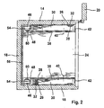
- a cover wall 38 can be attached to the right 14 and the left 16 side wall.
- This cover wall 38 consists of a folded sheet metal and has two standardized perforated strips 40, so that commercial attachments can be attached to it in a simple manner.
- This cover wall 38 has on its narrow side facing the door a folded web 42, so that the lying behind the cover wall 38 fastening device with carrier bar 26 and hanger 30 is optically hidden.
- the cover wall 38 extends from the door 20 to the rear wall 18 and extends over the entire height of the side walls 14, 16, so that the side walls are completely covered. In this case, the cover wall 38 is designed with a visually appealing surface, so that the interior of the vault hereby becomes very attractive.
- a groove 44 is formed, in which a lamp 46 is mounted.
- This lamp 46 is composed of a number of light sources, in particular light-emitting diodes and emits a daylight similar light. In this case, the lamp 46 extends over substantial parts of the respective side wall 14, 16, so that a uniform illumination of the interior of the safe is achieved.
- the lamp 46 is provided with a cover 48, wherein the lamp and the cover 48 are dimensioned together so that nothing projects beyond the groove 44. This ensures that attachments used on the lamp 46 and the cover 48 can be used to the back wall 18 verbei. As a result, an optimal utilization of the existing interior is achieved.
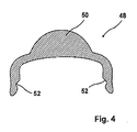
- a lens 50 is formed, which is designed as a semi-cylindrical lens. In this case, this lens 50 scatters the light of the lamp 46 in the interior, so that a uniform illumination of the interior of the vault takes place.
- undercuts 52 are formed on the cover 48, so that this cover 48 can be easily clipped onto the lamp 46 without the need for tedious screws or other fastening means.
- a plastic plate 56 is mounted directly in front of the rear wall 18.
- This plastic plate 56 is made of a transparent material, so that the light emanating from the light 46 illuminates the plastic plate 56, with the result that the rear part of the vault is also illuminated and thus provides a pleasant sight.
- the plastic plate 56 is provided on its side facing the interior of the vault with a rough surface.
- the individual light beams of the luminaire 46 impinge upon this rough surface and are diffusely reflected therefrom in the interior of the vault. This creates a very even and pleasant illumination of the interior.
- These add-on parts may be, for example, a telescopic extension 58, an extension table 22 attached thereto or a shelf 24, or an interior vault or the like, not shown here. It is also possible to attach to the extension table 22 two or more sockets 60 so that in Interior of the safe, for example, a computer or other electrical equipment can be connected.
Landscapes
- Engineering & Computer Science (AREA)
- General Engineering & Computer Science (AREA)
- Arrangement Of Elements, Cooling, Sealing, Or The Like Of Lighting Devices (AREA)
- Finishing Walls (AREA)
Applications Claiming Priority (1)
| Application Number | Priority Date | Filing Date | Title |
|---|---|---|---|
| DE102007061244A DE102007061244A1 (de) | 2007-12-19 | 2007-12-19 | Tresor |
Publications (2)
| Publication Number | Publication Date |
|---|---|
| EP2072739A2 true EP2072739A2 (fr) | 2009-06-24 |
| EP2072739A3 EP2072739A3 (fr) | 2013-01-09 |
Family
ID=40379753
Family Applications (1)
| Application Number | Title | Priority Date | Filing Date |
|---|---|---|---|
| EP08022025A Withdrawn EP2072739A3 (fr) | 2007-12-19 | 2008-12-18 | Coffre-fort |
Country Status (2)
| Country | Link |
|---|---|
| EP (1) | EP2072739A3 (fr) |
| DE (1) | DE102007061244A1 (fr) |
Cited By (1)
| Publication number | Priority date | Publication date | Assignee | Title |
|---|---|---|---|---|
| GB2568904A (en) * | 2017-11-29 | 2019-06-05 | Neptune Europe Ltd | Cabinet with LED |
Families Citing this family (1)
| Publication number | Priority date | Publication date | Assignee | Title |
|---|---|---|---|---|
| CN107125978A (zh) * | 2017-06-25 | 2017-09-05 | 张光裕 | 嵌套保险箱的柜子 |
Family Cites Families (5)
| Publication number | Priority date | Publication date | Assignee | Title |
|---|---|---|---|---|
| DE3505305A1 (de) * | 1985-02-15 | 1986-08-21 | Loukas Athen/Athenai Mitsakis | Sicherheitsschrank fuer zur staendigen handhabung bereitliegende bargeldbestaende oder wertsachen |
| US6044777A (en) * | 1998-02-09 | 2000-04-04 | Walsh; Michael J. | Composite metal safe and method of making |
| DE20210834U1 (de) * | 2002-07-17 | 2002-09-26 | Allegro-Möbel GmbH, 49328 Melle | Möbelbauteil |
| US7367685B2 (en) * | 2005-02-25 | 2008-05-06 | Nexlite | Lighted cabinet assembly |
| DE202006002032U1 (de) * | 2006-02-09 | 2006-06-01 | Maibom, Frank | Solarbetriebene LED-Schrankbeleuchtung mit Bewegungssensor |
-
2007
- 2007-12-19 DE DE102007061244A patent/DE102007061244A1/de not_active Withdrawn
-
2008
- 2008-12-18 EP EP08022025A patent/EP2072739A3/fr not_active Withdrawn
Non-Patent Citations (1)
| Title |
|---|
| None |
Cited By (1)
| Publication number | Priority date | Publication date | Assignee | Title |
|---|---|---|---|---|
| GB2568904A (en) * | 2017-11-29 | 2019-06-05 | Neptune Europe Ltd | Cabinet with LED |
Also Published As
| Publication number | Publication date |
|---|---|
| DE102007061244A1 (de) | 2009-06-25 |
| EP2072739A3 (fr) | 2013-01-09 |
Similar Documents
| Publication | Publication Date | Title |
|---|---|---|
| EP2180109A2 (fr) | Elément en mousse et absorbeur phonique fixé de manière suspendue | |
| AT509687A1 (de) | Trennwand mit integrierter beleuchtung | |
| DE19719184C1 (de) | Leuchte | |
| EP2072739A2 (fr) | Coffre-fort | |
| DE202013105914U1 (de) | Leuchte | |
| DE102007061391B4 (de) | Tresor | |
| DE202010001579U1 (de) | Beleuchtungsvorrichtung für ein bewegliches Möbelelement sowie Möbelelement | |
| DE202022106912U1 (de) | Möbel | |
| DE202009015021U1 (de) | Leuchte, insbesondere für den Ladenbau | |
| DE102012207540A1 (de) | Leuchte | |
| DE102014000558B3 (de) | Stehleuchte mit bifunktionalem Kopf | |
| EP2057915B1 (fr) | Plaque de recouvrement de meuble | |
| DE102008018128B9 (de) | Schrankmöbel | |
| DE102008033743A1 (de) | Leuchtwand | |
| DE102004052926B4 (de) | Mit einem Beleuchtungsmittel ausgestatteter Spiegel | |
| DE10311876A1 (de) | Regalvorsatzleuchte | |
| AT503261B1 (de) | Leuchtenanordnung sowie daraus hergestellter sichtschutz bzw. raumteiler | |
| DE102004006097B4 (de) | Möbelboden | |
| DE60128952T2 (de) | Lampe zur montage von zwei oder mehr leuchtstoffröhren | |
| DE102008019533A1 (de) | Regalanordnung | |
| DE20204458U1 (de) | Vorrichtung zum Beleuchten von Gegenständen und Räumen | |
| DE6608291U (de) | Zimmerhohe anbau-schrankwand. | |
| DE102024104761A1 (de) | Innenbeleuchtetes Kastenmöbel mit Fronttür | |
| DE3404895A1 (de) | Vorhangbeleuchtung | |
| DE19957976C2 (de) | Spiegel mit aufgebauter Leuchte |
Legal Events
| Date | Code | Title | Description |
|---|---|---|---|
| PUAI | Public reference made under article 153(3) epc to a published international application that has entered the european phase |
Free format text: ORIGINAL CODE: 0009012 |
|
| AK | Designated contracting states |
Kind code of ref document: A2 Designated state(s): AT BE BG CH CY CZ DE DK EE ES FI FR GB GR HR HU IE IS IT LI LT LU LV MC MT NL NO PL PT RO SE SI SK TR |
|
| AX | Request for extension of the european patent |
Extension state: AL BA MK RS |
|
| PUAL | Search report despatched |
Free format text: ORIGINAL CODE: 0009013 |
|
| AK | Designated contracting states |
Kind code of ref document: A3 Designated state(s): AT BE BG CH CY CZ DE DK EE ES FI FR GB GR HR HU IE IS IT LI LT LU LV MC MT NL NO PL PT RO SE SI SK TR |
|
| AX | Request for extension of the european patent |
Extension state: AL BA MK RS |
|
| RIC1 | Information provided on ipc code assigned before grant |
Ipc: F21V 33/00 20060101ALI20121204BHEP Ipc: E05G 1/024 20060101ALI20121204BHEP Ipc: E05G 1/02 20060101AFI20121204BHEP |
|
| 17P | Request for examination filed |
Effective date: 20130704 |
|
| RBV | Designated contracting states (corrected) |
Designated state(s): AT BE BG CH CY CZ DE DK EE ES FI FR GB GR HR HU IE IS IT LI LT LU LV MC MT NL NO PL PT RO SE SI SK TR |
|
| AKX | Designation fees paid |
Designated state(s): AT BE BG CH CY LI |
|
| REG | Reference to a national code |
Ref country code: DE Ref legal event code: R108 |
|
| RBV | Designated contracting states (corrected) |
Designated state(s): AT BE BG CH CY CZ LI |
|
| REG | Reference to a national code |
Ref country code: DE Ref legal event code: R108 Effective date: 20130911 |
|
| STAA | Information on the status of an ep patent application or granted ep patent |
Free format text: STATUS: THE APPLICATION IS DEEMED TO BE WITHDRAWN |
|
| 18D | Application deemed to be withdrawn |
Effective date: 20140701 |