EP2072746A2 - Système de module de porte pour une porte d'entrée, vantail et porte - Google Patents
Système de module de porte pour une porte d'entrée, vantail et porte Download PDFInfo
- Publication number
- EP2072746A2 EP2072746A2 EP08172028A EP08172028A EP2072746A2 EP 2072746 A2 EP2072746 A2 EP 2072746A2 EP 08172028 A EP08172028 A EP 08172028A EP 08172028 A EP08172028 A EP 08172028A EP 2072746 A2 EP2072746 A2 EP 2072746A2
- Authority
- EP
- European Patent Office
- Prior art keywords
- door
- receiving
- module system
- unit
- leaf
- Prior art date
- Legal status (The legal status is an assumption and is not a legal conclusion. Google has not performed a legal analysis and makes no representation as to the accuracy of the status listed.)
- Withdrawn
Links
- 238000005192 partition Methods 0.000 claims description 8
- 238000012544 monitoring process Methods 0.000 claims description 3
- 230000001747 exhibiting effect Effects 0.000 abstract 1
- 230000001681 protective effect Effects 0.000 description 3
- 238000011161 development Methods 0.000 description 2
- 230000018109 developmental process Effects 0.000 description 2
- 239000011521 glass Substances 0.000 description 2
- 239000000203 mixture Substances 0.000 description 2
- 241000544076 Whipplea modesta Species 0.000 description 1
- 230000000295 complement effect Effects 0.000 description 1
- 230000001419 dependent effect Effects 0.000 description 1
- 230000000694 effects Effects 0.000 description 1
- 230000002452 interceptive effect Effects 0.000 description 1
- 230000001788 irregular Effects 0.000 description 1
- 238000004519 manufacturing process Methods 0.000 description 1
- 239000000463 material Substances 0.000 description 1
Images





Classifications
-
- E—FIXED CONSTRUCTIONS
- E06—DOORS, WINDOWS, SHUTTERS, OR ROLLER BLINDS IN GENERAL; LADDERS
- E06B—FIXED OR MOVABLE CLOSURES FOR OPENINGS IN BUILDINGS, VEHICLES, FENCES OR LIKE ENCLOSURES IN GENERAL, e.g. DOORS, WINDOWS, BLINDS, GATES
- E06B3/00—Window sashes, door leaves, or like elements for closing wall or like openings; Layout of fixed or moving closures, e.g. windows in wall or like openings; Features of rigidly-mounted outer frames relating to the mounting of wing frames
- E06B3/70—Door leaves
-
- E—FIXED CONSTRUCTIONS
- E06—DOORS, WINDOWS, SHUTTERS, OR ROLLER BLINDS IN GENERAL; LADDERS
- E06B—FIXED OR MOVABLE CLOSURES FOR OPENINGS IN BUILDINGS, VEHICLES, FENCES OR LIKE ENCLOSURES IN GENERAL, e.g. DOORS, WINDOWS, BLINDS, GATES
- E06B3/00—Window sashes, door leaves, or like elements for closing wall or like openings; Layout of fixed or moving closures, e.g. windows in wall or like openings; Features of rigidly-mounted outer frames relating to the mounting of wing frames
- E06B3/70—Door leaves
- E06B2003/7046—Door leaves with provisions for locks, hinges or other fittings
Definitions
- the present invention relates to a door module system for a front door, a door leaf, in particular a front door leaf, with such a door module system and a door, in particular a front door, with such a door module system or such a door leaf.
- a door plate with a dynamically controllable display in particular in the form of an LCD display disclosed.
- An interface allows the input of information, in particular by means of keyboard or Bluetooth receiver.
- an output means for outputting information in font / image representation can be provided.
- the DE 20 2006 019 731 U1 a door system with a door leaf, in which an electronic display is integrated, on which an interactive user interface can be displayed.
- the DE 20 2006 000 931 U1 a door fitting for receiving a door handle with a motion detector, which is activated by a twilight switch in the dark.
- the door fitting has a door handle combined with an illuminated handle.
- the door handle takes on a light-emitting diode, which is turned on in the dark and emits light in the handle.
- the invention has for its object to provide a simple to produce and at the same time flexible door system.
- a door panel equipped with such a door module system as well as a door equipped with such a door panel or such a door module system are objects of the secondary claims.
- One idea of the invention is to provide a multifunctional door module system with a plurality of door function modules, which are optionally distributed on a plurality of receiving places, in particular optionally.
- the user can therefore select which door function module is to be positioned in which location.
- the door function modules can be interchangeable, for example, fixed with a detachable connection, optionally at the receiving stations and / or removed.
- this interchangeability is designed so that the door is sufficiently secure protected against burglary and / or sabotage.
- it is in the door module system is a kind of modular system, where composed of a variety of door function modules according to the customer a desired variation and the selected door function modules can be mounted in the desired position in the receiving locations.
- door module system is understood in particular to be a type of modular system, ie a specific number of module units and one or more types of module units are assembled from a group of several modules. In other words, it is a multifunctional door system, whereby the door can be used for building completion or even inside a building.
- At least two of the receiving stations have the same dimensions and form a first group of seats, wherein at least one of the door function modules is adapted to these dimensions of the first receiving space group, that the door function module can be accommodated in one of the receiving locations of the first receiving space group.
- a plurality of receiving locations each provide a receiving space, each having the same width, the same height and the same depth.
- several door function modules of different types can be provided with the appropriate dimensions, so that the customer can bring the door function modules depending on his needs in the desired seats.
- the door module system may also comprise adapter modules with which, for example, a door function module tuned to the second reception space group can be introduced into the first reception space group.
- the door function module comprises at least one functional unit and a fastening unit, wherein the fastening unit is connectable by means of a detachable or a permanent connection with the receptacle.
- the configuration and the dimensions of the fastening unit are preferably determined by the receiving places.
- the outer surface of the fastening unit may be formed complementary to the receiving space, ie to the space provided by the receiving space.
- the fastening unit connectable by means of a detachable or a permanent connection with the recording.
- flexibility of the door module system is made possible during the entire service life of the door module system or the door.
- the releasable connection may for example comprise a latching connection or consist of such.
- the attachment unit has a latching element, such as a latching head, and the associated receiving space having an associated latching groove. Even with a detachable connection measures can be taken to prevent burglary and / or sabotage.
- a monitoring unit As a functional unit of the door function module, a monitoring unit, an operating unit (eg bell switch), a lighting unit, a display unit (eg display), a communication unit, a microphone unit, a speaker unit, a screen unit, a protective screen unit or a door handle unit can be provided. Furthermore, a camera, a motion detector, a display, an interface, a mechanical safety device, such as a door lock, a biometric safety device (for example a fingerprint sensor), an RFID sensor, a Bluetooth receiver, a keyboard and also a door fitting as a functional unit be used. Furthermore, a door handle can be integrated into one of the functional units, provided separately on the door leaf or the receptacle are shaped accordingly to serve as a handle.
- the receptacle has a receiving housing which can be fixed to a door leaf.
- This receiving housing may be formed one or more parts.
- the receiving housing extends along the height of the door in the installed state.
- at least a portion of the receiving housing may be adapted to be gripped by a hand for operating the door.
- the receiving housing in cross-section may be formed approximately T-shaped.
- the receiving housing may be formed such that for mounting the receptacle on the door fastening means, such as screws, are positioned at a position later, d. H. after assembly, are not accessible from the outside.
- the door module system, the receptacle or a receiving housing of the receptacle can be designed in the form of a door strip which can be fastened to the door leaf and have at least one connection for attachment to the door leaf.
- the connection may be formed as a connection surface extending over the entire strip or in the form of two connection regions in the end regions of the door strip. When forming a connection surface, this can thus be completely attached to a mounting surface of a door leaf.
- the connection surface and thus the door strip can extend over the entire height or width of the door leaf or a corresponding partial area.
- the door strip on a receiving channel, which provides the recording slots.
- the receiving channel can be designed such that the receiving places are flexibly divisible or adjustable along the longitudinal direction of the door strip. So, for example be provided variably positionable partitions to divide the seats flexible along the longitudinal direction of the door bar or to adjust. It can be provided slots in which the partitions can be inserted and removed if necessary. In this way, the position of the individual door function module, but also the size of the receiving space is determined by positioning the partitions. For example, the partitions in different slots can be plugged in and out.
- the slots can be grid-like distributed over the receiving channel in the same or different distances. For example, the customer may, in coordination with the compilation of the door function modules, select a corresponding basic system for a door strip with a receiving channel with a predetermined grid for the slots.
- the door leaf according to the invention in particular in the form of a front door leaf, comprises such a door module system according to the invention and thus makes use of its advantages.
- the door leaf comprises a recess, wherein the receptacle is at least partially received in the recess or the door leaf has an outer side, wherein the receptacle are attached to the outside.
- the receiving housing and / or the door strip can be received in the recess or attached to the outside.
- at least one section for example a fastening section, can be fixed in the recess.
- at least one of the door function modules can be operated or accessed from an inner side and / or an outer side of the door leaf. For example, from the outside of a keyboard or bell and from the inside of a touchscreen screen and / or a door handle can be operated.
- the door according to the invention in particular in the form of a front door, comprises a door module system according to one of claims 1 to 11 or a door leaf according to one of claims 12 to 14.
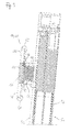
- FIGS. 1 to 5 show a first embodiment of a door module system according to the invention of a door leaf 50 of a front door.
- Fig. 2 shows a cross section through the entire door leaf 50 along the line II-II in Fig. 1 ,
- the door leaf is rotatably mounted about a rotation axis 58 and has an inner side 54 and an outer side 56.
- Fig. 3 shows an enlarged section Fig. 2 and shows the door module system in the form of a door bar 60 which is attached to the outside 56 of the door panel 50.
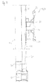
- the show FIGS. 4 and 5 further cross sections through the door leaf 50.
- the door module system includes a plurality of door function modules 10 and a receptacle 20 having a plurality of receiving seats 22, 23, 24, 25 and 26 for mounting the door function modules 10.
- the receiving places 22 to 24 form a first receiving place group 27 and the receiving place 25 a second receiving place group 28.
- the receiving places 22 to 24 can have the same dimensions, i. for example, based on the width, the height and the depth of the receiving space forming free space, with irregular cross-sectional shapes are possible.
- the door function modules 10 are correspondingly adapted to these dimensions in order to be received in the receiving places 22 to 26.
- the door function modules 10 can also be subdivided into different groups, which then have dimensions assigned to the reception space groups. In this way, a kind of modular system is provided, from which the user then depending on his requirements, the desired door function modules 10 and a receptacle 20, for example in the form of a T-shaped receiving housing 30, select and attach to the door rail 60.
- each door function module 10 is equipped with a functional unit 14 to 18 and a fastening unit 12.
- the attachment unit 12 is essentially intended to be a temporary one or to allow permanent attachment of the door function module 10 in a receiving space of the receptacle 20.
- the functional unit may comprise a monitoring unit, an operating unit, a lighting unit, a door handle unit, a screen unit, a display unit, a speaker unit, a communication unit and / or a microphone unit.
- a functional unit can also fulfill several functions. How out Fig.
- a functional unit 14 comprises a code button, as a functional unit 15 a bell button, as a functional unit 16 a light switch, as a functional unit 17 a Fingerscanech and as a functional unit 18, a display unit for displaying street and / or house number.
- the receiving housing 30 of the receptacle 20 comprises a receiving channel 32 which extends along the height of the door leaf 50 and which provides the receiving locations 22 to 26.
- a first terminal 34 of the receiving housing 30 is attached to the door panel 50.
- a second terminal 36 is attached to the door panel 50 in the region of a second end of the bar 60.
- Fig. 4 shows, in the present embodiment for the first terminal 34 and accordingly for the second terminal 36 as fastening means in each case two screws 59 are provided which connect the door bar 60 with the door panel 50.
- a module carrier 40 is provided (see Fig. 3 ).
- the door function modules 10 are introduced with their attachment unit 12 in the desired receiving space 22 to 26 and then fixed to the module carrier 40. It is also possible to fix a plurality of door function modules 10 to a module carrier 40. In an alternative attachment can a latching connection for fixing the door function module 10 and the door function modules 10 are used on the receptacle 20.
- a screen 42 or a protective cover 44 on the receiving housing 30 and / or the door function module 10 or the door function modules 10 are fixed so that the door function modules 10 are protected against unauthorized access.
- a screen 42 for example, a design sheet
- Fig. 5 in an upper region of the door strip 60, a glass element as a screen 42, which in turn is fixed to the module carrier 40.
- a protective screen 44 for example also with a glass pane element, can be provided in the Fig. 1
- the door strip 60 has a total of a T-shape viewed in cross section, wherein a first end 62 and a second end 64 are each formed in the form of a free end.
- This T-shape has the advantage that on the one hand, the receiving channel 32 can be provided with the receiving stations 22 to 26 and also created by the two free ends 62, 64 one or two outer door handles in that the two ends 62, 64 are adapted to be grasped for opening or closing from the outside 56 of a hand.
- FIGS. 6 to 8 show a second embodiment of a door module system according to the invention of a door leaf 70 of a front door.
- the front door further comprises a door frame 100.
- Those reference numerals already to of the first embodiment are provided in an analog form in the second embodiment. For the sake of simplicity, reference is made in this regard to the explanations on the first embodiment.
- FIG. 7 shows a cross section through the door panel 70, which has an inner side 72 and an outer side 74.
- the FIGS. 6 and 7 show a cable guide 90, which can be supplied via the frame 100, for example in the region of an upper and / or lower hinge hinge in the door panel 70.
- the cable guide 90 may include, for example, a power line and / or a data line and provide the function modules 10 to 19 of the door function modules 10 with power and / or data.
- Fig. 8 shows in a similar way as the Figures 2 and 3 a cross section through the door panel 70 in the field of functional units.
- the door module system comprises a plurality of door function modules 10, which are described in greater detail below, and a receptacle 20 having a receptacle housing 30.
- the receptacle housing 30 forms a receptacle 32, which provides a plurality of receptacles 22 to 26 for attaching the door function modules 10.
- the receptacle 20 or the receiving housing 30 is in the form of a door strip 80, which is fastened to the outer side 74 of the door leaf 70.
- the door strip 80 is considered in its entire longitudinal direction over the entire surface on the outside 74 and is fixed there.
- the receiving channel 32 may, for example, be designed such that the receiving places 22 to 26 are flexibly divisible or adjustable along the longitudinal direction of the door strip 80.
- variably positionable partitions can be provided in order to divide or adjust the receiving places 22 to 26 flexibly along the longitudinal direction of the door strip 80 or of the receiving channel 32.
- Next slots can be provided for the partitions.
- the door module system comprises purely by way of example as a functional unit 15 a doorbell and / or a code button, as a functional unit 18, a display unit for displaying street and / or house number and as a functional unit 19, a communication unit, such as an intercom.
- the door strip 80 has a total of a T-shape viewed in cross-section, wherein a first end 82 and a second end 84 are each formed in the form of a free end.
- This T-shape has the advantage that on the one hand, the receiving channel 32 can be provided with the receiving stations 22 to 26 and also created by the two free ends 82, 84 one or two outer door handles in that the two ends 82, 84 are adapted to be grasped for opening or closing from the outside 74 of one hand.
- FIG. 8 shows are for fixing the door strip 80 on the door panel 70, so that the door strip 80 rests on the outside 74 of the door leaf 70, viewed in cross section as fastening means, for example, two screws 79, two nuts 76, two setscrews 77 and two nuts 78 is provided.
- the outer side 74 thus represents a connection surface which can extend over the entire height (or width) of the door leaf 70 or a corresponding partial area.
- a plurality of these fastening means can be provided distributed over the longitudinal direction of the door strip 80.
- the screws 79 e.g., jet nut
- the plate 50 can also be referred to as a panel and optionally serve as a fastening unit 12.
- the described embodiments enable a multifunctional door module system, whereby a diverse combination of different door function modules and their attachment in a simpler manner is possible.
- a desired door module system can be selected and fastened, for example, as a door strip 60, 80 on the outside 56, 74 of the door leaf 50, 70.
- the door strip 60, 80 could also be introduced into a recess of the door leaf 50, 70, for example also such that the outer surface of the door module system is flush with the outer side 54, 74 of the door leaf 50.
- this flexible design allows a change in the composition and optionally a different positioning of the door function modules 10 along the door rail 60, 80, so that over the life of the door leaf 50, 70 and / or the door module system, a change of the door module system and its door function modules 10 is possible.
Landscapes
- Engineering & Computer Science (AREA)
- Civil Engineering (AREA)
- Structural Engineering (AREA)
- Wing Frames And Configurations (AREA)
- Casings For Electric Apparatus (AREA)
Applications Claiming Priority (1)
| Application Number | Priority Date | Filing Date | Title |
|---|---|---|---|
| DE200720017581 DE202007017581U1 (de) | 2007-12-17 | 2007-12-17 | Türmodulsystem für eine Haustür, Türblatt und Tür |
Publications (2)
| Publication Number | Publication Date |
|---|---|
| EP2072746A2 true EP2072746A2 (fr) | 2009-06-24 |
| EP2072746A3 EP2072746A3 (fr) | 2013-04-10 |
Family
ID=40428065
Family Applications (1)
| Application Number | Title | Priority Date | Filing Date |
|---|---|---|---|
| EP08172028.6A Withdrawn EP2072746A3 (fr) | 2007-12-17 | 2008-12-17 | Système de module de porte pour une porte d'entrée, vantail et porte |
Country Status (2)
| Country | Link |
|---|---|
| EP (1) | EP2072746A3 (fr) |
| DE (1) | DE202007017581U1 (fr) |
Cited By (5)
| Publication number | Priority date | Publication date | Assignee | Title |
|---|---|---|---|---|
| CZ306008B6 (cs) * | 2015-03-25 | 2016-06-15 | Václav Ridl | Bezpečnostní zařízení na dveře |
| EP2241715B2 (fr) † | 2009-04-06 | 2018-02-14 | Hörmann KG Eckelhausen | Porte d'habitation avec matière synthétique fibreuse renforcé et procédé de fabrication |
| CN108868492A (zh) * | 2018-07-19 | 2018-11-23 | 南乐千禧人门业有限公司 | 一种双层模块化外门 |
| CN113187356A (zh) * | 2021-04-26 | 2021-07-30 | 泰森日盛集团有限公司 | 一种基于rfid技术的木门及其使用方法 |
| DE102012102514C5 (de) | 2011-03-23 | 2023-12-21 | Zoran Sencar | Türblatt |
Families Citing this family (2)
| Publication number | Priority date | Publication date | Assignee | Title |
|---|---|---|---|---|
| DE202017006423U1 (de) | 2017-12-13 | 2018-04-03 | Herbert Bäumchen | Smart Home Haustür |
| US20190257142A1 (en) * | 2018-02-18 | 2019-08-22 | Russet Labs, Llc | System and method for a modular door structure |
Citations (5)
| Publication number | Priority date | Publication date | Assignee | Title |
|---|---|---|---|---|
| DE1640316B1 (de) * | 1965-04-22 | 1970-12-23 | Tech Unie N V | Leitungsschiene |
| DE2801852A1 (de) * | 1977-02-04 | 1978-08-10 | Bassani Spa | Installationsmittel fuer die anordnung einer tv-kamera fuer den video-wechselsprechverkehr in einem tableau fuer einen elektrischen tueroeffner |
| DE20302302U1 (de) | 2003-02-13 | 2003-04-30 | Deutsch, Alexander Maximilian, 40597 Düsseldorf | Türschild mit dynamisch steuerbarer Anzeige |
| DE202006000931U1 (de) | 2006-01-21 | 2006-03-30 | Kobusch, Klaus, Dipl.-Ing. | Türbeschlag mit integriertem, netzunabhängigem Bewegungsmelder und Beleuchtung |
| DE202006019731U1 (de) | 2006-12-29 | 2007-04-12 | Buchal Thomas | Türanlage |
Family Cites Families (10)
| Publication number | Priority date | Publication date | Assignee | Title |
|---|---|---|---|---|
| CH671803A5 (fr) * | 1986-11-04 | 1989-09-29 | Geilinger Ag | |
| DE29717647U1 (de) * | 1997-10-05 | 1999-02-04 | HEWI Heinrich Wilke GmbH, 34454 Bad Arolsen | Informations- und Kommunikationseinrichtung |
| DE19816390C2 (de) * | 1998-04-11 | 2000-02-24 | Loh Kg Ritto Werk | Aufnahmegehäuse für Moduleinheiten einer Türstation einer Türsprechanlage |
| FR2785324B1 (fr) * | 1998-11-02 | 2001-01-19 | Unitechniques | Dispositif de controle de l'ouverture d'une porte |
| DE19943041A1 (de) * | 1999-09-09 | 2001-03-15 | Geze Gmbh | Gebäudeausgangsvorrichtung |
| DE20014556U1 (de) * | 2000-08-23 | 2001-01-18 | Buchal, Thomas, 58091 Hagen | Türaußengriff |
| DE10043979A1 (de) * | 2000-09-05 | 2002-03-14 | Geze Gmbh | Sicherungs- und/oder Überwachungsvorrichtung |
| EP1229189A1 (fr) * | 2001-02-05 | 2002-08-07 | Schneider + Fichtel GmbH | Poignée de porte |
| DE20312860U1 (de) * | 2003-08-20 | 2003-10-30 | Lebo Türenwerke Johann Lensing GmbH & Co KG, 46395 Bocholt | Tür |
| DE102005001628A1 (de) * | 2005-01-12 | 2006-07-20 | Dorma Gmbh + Co. Kg | Profil |
-
2007
- 2007-12-17 DE DE200720017581 patent/DE202007017581U1/de not_active Expired - Lifetime
-
2008
- 2008-12-17 EP EP08172028.6A patent/EP2072746A3/fr not_active Withdrawn
Patent Citations (5)
| Publication number | Priority date | Publication date | Assignee | Title |
|---|---|---|---|---|
| DE1640316B1 (de) * | 1965-04-22 | 1970-12-23 | Tech Unie N V | Leitungsschiene |
| DE2801852A1 (de) * | 1977-02-04 | 1978-08-10 | Bassani Spa | Installationsmittel fuer die anordnung einer tv-kamera fuer den video-wechselsprechverkehr in einem tableau fuer einen elektrischen tueroeffner |
| DE20302302U1 (de) | 2003-02-13 | 2003-04-30 | Deutsch, Alexander Maximilian, 40597 Düsseldorf | Türschild mit dynamisch steuerbarer Anzeige |
| DE202006000931U1 (de) | 2006-01-21 | 2006-03-30 | Kobusch, Klaus, Dipl.-Ing. | Türbeschlag mit integriertem, netzunabhängigem Bewegungsmelder und Beleuchtung |
| DE202006019731U1 (de) | 2006-12-29 | 2007-04-12 | Buchal Thomas | Türanlage |
Cited By (6)
| Publication number | Priority date | Publication date | Assignee | Title |
|---|---|---|---|---|
| EP2241715B2 (fr) † | 2009-04-06 | 2018-02-14 | Hörmann KG Eckelhausen | Porte d'habitation avec matière synthétique fibreuse renforcé et procédé de fabrication |
| DE102012102514C5 (de) | 2011-03-23 | 2023-12-21 | Zoran Sencar | Türblatt |
| CZ306008B6 (cs) * | 2015-03-25 | 2016-06-15 | Václav Ridl | Bezpečnostní zařízení na dveře |
| CN108868492A (zh) * | 2018-07-19 | 2018-11-23 | 南乐千禧人门业有限公司 | 一种双层模块化外门 |
| CN108868492B (zh) * | 2018-07-19 | 2023-12-29 | 南乐千禧人门业有限公司 | 一种双层模块化外门 |
| CN113187356A (zh) * | 2021-04-26 | 2021-07-30 | 泰森日盛集团有限公司 | 一种基于rfid技术的木门及其使用方法 |
Also Published As
| Publication number | Publication date |
|---|---|
| DE202007017581U1 (de) | 2009-04-30 |
| EP2072746A3 (fr) | 2013-04-10 |
Similar Documents
| Publication | Publication Date | Title |
|---|---|---|
| EP2072746A2 (fr) | Système de module de porte pour une porte d'entrée, vantail et porte | |
| EP0756661B1 (fr) | Systeme de fermeture a serrure interieure variable | |
| EP0972124B1 (fr) | Pene modulaire | |
| DE29507235U1 (de) | Kraftfahrzeugtür | |
| DE3419773C2 (de) | Taxameter | |
| DE102015111560B4 (de) | Adapter für die Kontaktierung eines Leistungsschalters an einem Sammelschienensystem | |
| EP0862252B1 (fr) | Armoire pour composants électriques et électroniques | |
| EP1856355B1 (fr) | Fenetre ou porte | |
| EP1455034A2 (fr) | Gâche à lame | |
| EP1736622A1 (fr) | Barrilet à bouton | |
| DE102007002397B4 (de) | Elektrisches Gerät zur Steuerung eines Haustechniksystems | |
| DE4411290A1 (de) | Sensor | |
| DE102014113637A1 (de) | Fluchtwegsicherungseinrichtung | |
| EP1612362A1 (fr) | Battant dans un cadre dormant avec un entraînement | |
| EP2644063B1 (fr) | Système de montage modulaire | |
| DE19963022A1 (de) | Sicherheitsvorrichtung für mindestens eine Tür, vorzugsweise in Flucht- und Rettungswegen | |
| EP1650512A2 (fr) | Réfrigérateur | |
| EP2930809B1 (fr) | Appareil d'installation électrique/électronique | |
| EP0951117A1 (fr) | Ensemble de fenêtre | |
| EP1449988B1 (fr) | Module de retenue pour ferrure de fenêtre ou de porte | |
| EP3118396B1 (fr) | Pêne dormant comprenant un moteur électrique | |
| EP2998488A1 (fr) | Dispositif de sécurité d'issue de secours | |
| DE29604113U1 (de) | Computergehäuse | |
| DE102013105893B3 (de) | Elektrisches/elektronisches Installationsgerät | |
| EP2437364A2 (fr) | Insert de profil de cadre, installation de battant en étant équipée et procédé de montage correspondant |
Legal Events
| Date | Code | Title | Description |
|---|---|---|---|
| PUAI | Public reference made under article 153(3) epc to a published international application that has entered the european phase |
Free format text: ORIGINAL CODE: 0009012 |
|
| AK | Designated contracting states |
Kind code of ref document: A2 Designated state(s): AT BE BG CH CY CZ DE DK EE ES FI FR GB GR HR HU IE IS IT LI LT LU LV MC MT NL NO PL PT RO SE SI SK TR |
|
| AX | Request for extension of the european patent |
Extension state: AL BA MK RS |
|
| PUAL | Search report despatched |
Free format text: ORIGINAL CODE: 0009013 |
|
| AK | Designated contracting states |
Kind code of ref document: A3 Designated state(s): AT BE BG CH CY CZ DE DK EE ES FI FR GB GR HR HU IE IS IT LI LT LU LV MC MT NL NO PL PT RO SE SI SK TR |
|
| AX | Request for extension of the european patent |
Extension state: AL BA MK RS |
|
| RIC1 | Information provided on ipc code assigned before grant |
Ipc: E06B 3/70 20060101AFI20130305BHEP |
|
| 17P | Request for examination filed |
Effective date: 20131008 |
|
| RBV | Designated contracting states (corrected) |
Designated state(s): AT BE BG CH CY CZ DE DK EE ES FI FR GB GR HR HU IE IS IT LI LT LU LV MC MT NL NO PL PT RO SE SI SK TR |
|
| AKX | Designation fees paid |
Designated state(s): AT CH DE LI |
|
| 17Q | First examination report despatched |
Effective date: 20160831 |
|
| GRAP | Despatch of communication of intention to grant a patent |
Free format text: ORIGINAL CODE: EPIDOSNIGR1 |
|
| INTG | Intention to grant announced |
Effective date: 20170606 |
|
| STAA | Information on the status of an ep patent application or granted ep patent |
Free format text: STATUS: THE APPLICATION IS DEEMED TO BE WITHDRAWN |
|
| 18D | Application deemed to be withdrawn |
Effective date: 20171017 |