EP2072770A2 - Katalysator zur Behandlung von Verbrennungsabgasen - Google Patents
Katalysator zur Behandlung von Verbrennungsabgasen Download PDFInfo
- Publication number
- EP2072770A2 EP2072770A2 EP08105658A EP08105658A EP2072770A2 EP 2072770 A2 EP2072770 A2 EP 2072770A2 EP 08105658 A EP08105658 A EP 08105658A EP 08105658 A EP08105658 A EP 08105658A EP 2072770 A2 EP2072770 A2 EP 2072770A2
- Authority
- EP
- European Patent Office
- Prior art keywords
- electrode
- layer
- catalyst
- catalyst according
- catalytically active
- Prior art date
- Legal status (The legal status is an assumption and is not a legal conclusion. Google has not performed a legal analysis and makes no representation as to the accuracy of the status listed.)
- Withdrawn
Links
Images

Classifications
-
- F—MECHANICAL ENGINEERING; LIGHTING; HEATING; WEAPONS; BLASTING
- F01—MACHINES OR ENGINES IN GENERAL; ENGINE PLANTS IN GENERAL; STEAM ENGINES
- F01N—GAS-FLOW SILENCERS OR EXHAUST APPARATUS FOR MACHINES OR ENGINES IN GENERAL; GAS-FLOW SILENCERS OR EXHAUST APPARATUS FOR INTERNAL-COMBUSTION ENGINES
- F01N3/00—Exhaust or silencing apparatus having means for purifying, rendering innocuous, or otherwise treating exhaust
- F01N3/01—Exhaust or silencing apparatus having means for purifying, rendering innocuous, or otherwise treating exhaust by means of electric or electrostatic separators
-
- B—PERFORMING OPERATIONS; TRANSPORTING
- B01—PHYSICAL OR CHEMICAL PROCESSES OR APPARATUS IN GENERAL
- B01D—SEPARATION
- B01D53/00—Separation of gases or vapours; Recovering vapours of volatile solvents from gases; Chemical or biological purification of waste gases, e.g. engine exhaust gases, smoke, fumes, flue gases, aerosols
- B01D53/32—Separation of gases or vapours; Recovering vapours of volatile solvents from gases; Chemical or biological purification of waste gases, e.g. engine exhaust gases, smoke, fumes, flue gases, aerosols by electrical effects other than those provided for in group B01D61/00
- B01D53/326—Separation of gases or vapours; Recovering vapours of volatile solvents from gases; Chemical or biological purification of waste gases, e.g. engine exhaust gases, smoke, fumes, flue gases, aerosols by electrical effects other than those provided for in group B01D61/00 in electrochemical cells
-
- B—PERFORMING OPERATIONS; TRANSPORTING
- B01—PHYSICAL OR CHEMICAL PROCESSES OR APPARATUS IN GENERAL
- B01D—SEPARATION
- B01D53/00—Separation of gases or vapours; Recovering vapours of volatile solvents from gases; Chemical or biological purification of waste gases, e.g. engine exhaust gases, smoke, fumes, flue gases, aerosols
- B01D53/34—Chemical or biological purification of waste gases
- B01D53/74—General processes for purification of waste gases; Apparatus or devices specially adapted therefor
- B01D53/86—Catalytic processes
- B01D53/8621—Removing nitrogen compounds
- B01D53/8625—Nitrogen oxides
- B01D53/8628—Processes characterised by a specific catalyst
-
- B—PERFORMING OPERATIONS; TRANSPORTING
- B01—PHYSICAL OR CHEMICAL PROCESSES OR APPARATUS IN GENERAL
- B01D—SEPARATION
- B01D53/00—Separation of gases or vapours; Recovering vapours of volatile solvents from gases; Chemical or biological purification of waste gases, e.g. engine exhaust gases, smoke, fumes, flue gases, aerosols
- B01D53/34—Chemical or biological purification of waste gases
- B01D53/92—Chemical or biological purification of waste gases of engine exhaust gases
- B01D53/94—Chemical or biological purification of waste gases of engine exhaust gases by catalytic processes
- B01D53/9445—Simultaneously removing carbon monoxide, hydrocarbons or nitrogen oxides making use of three-way catalysts [TWC] or four-way-catalysts [FWC]
- B01D53/9454—Simultaneously removing carbon monoxide, hydrocarbons or nitrogen oxides making use of three-way catalysts [TWC] or four-way-catalysts [FWC] characterised by a specific device
-
- F—MECHANICAL ENGINEERING; LIGHTING; HEATING; WEAPONS; BLASTING
- F01—MACHINES OR ENGINES IN GENERAL; ENGINE PLANTS IN GENERAL; STEAM ENGINES
- F01N—GAS-FLOW SILENCERS OR EXHAUST APPARATUS FOR MACHINES OR ENGINES IN GENERAL; GAS-FLOW SILENCERS OR EXHAUST APPARATUS FOR INTERNAL-COMBUSTION ENGINES
- F01N3/00—Exhaust or silencing apparatus having means for purifying, rendering innocuous, or otherwise treating exhaust
- F01N3/08—Exhaust or silencing apparatus having means for purifying, rendering innocuous, or otherwise treating exhaust for rendering innocuous
- F01N3/0892—Electric or magnetic treatment, e.g. dissociation of noxious components
-
- F—MECHANICAL ENGINEERING; LIGHTING; HEATING; WEAPONS; BLASTING
- F01—MACHINES OR ENGINES IN GENERAL; ENGINE PLANTS IN GENERAL; STEAM ENGINES
- F01N—GAS-FLOW SILENCERS OR EXHAUST APPARATUS FOR MACHINES OR ENGINES IN GENERAL; GAS-FLOW SILENCERS OR EXHAUST APPARATUS FOR INTERNAL-COMBUSTION ENGINES
- F01N3/00—Exhaust or silencing apparatus having means for purifying, rendering innocuous, or otherwise treating exhaust
- F01N3/08—Exhaust or silencing apparatus having means for purifying, rendering innocuous, or otherwise treating exhaust for rendering innocuous
- F01N3/10—Exhaust or silencing apparatus having means for purifying, rendering innocuous, or otherwise treating exhaust for rendering innocuous by thermal or catalytic conversion of noxious components of exhaust
- F01N3/18—Exhaust or silencing apparatus having means for purifying, rendering innocuous, or otherwise treating exhaust for rendering innocuous by thermal or catalytic conversion of noxious components of exhaust characterised by methods of operation; Control
- F01N3/20—Exhaust or silencing apparatus having means for purifying, rendering innocuous, or otherwise treating exhaust for rendering innocuous by thermal or catalytic conversion of noxious components of exhaust characterised by methods of operation; Control specially adapted for catalytic conversion
- F01N3/2006—Periodically heating or cooling catalytic reactors, e.g. at cold starting or overheating
- F01N3/2013—Periodically heating or cooling catalytic reactors, e.g. at cold starting or overheating using electric or magnetic heating means
-
- F—MECHANICAL ENGINEERING; LIGHTING; HEATING; WEAPONS; BLASTING
- F01—MACHINES OR ENGINES IN GENERAL; ENGINE PLANTS IN GENERAL; STEAM ENGINES
- F01N—GAS-FLOW SILENCERS OR EXHAUST APPARATUS FOR MACHINES OR ENGINES IN GENERAL; GAS-FLOW SILENCERS OR EXHAUST APPARATUS FOR INTERNAL-COMBUSTION ENGINES
- F01N3/00—Exhaust or silencing apparatus having means for purifying, rendering innocuous, or otherwise treating exhaust
- F01N3/08—Exhaust or silencing apparatus having means for purifying, rendering innocuous, or otherwise treating exhaust for rendering innocuous
- F01N3/10—Exhaust or silencing apparatus having means for purifying, rendering innocuous, or otherwise treating exhaust for rendering innocuous by thermal or catalytic conversion of noxious components of exhaust
- F01N3/18—Exhaust or silencing apparatus having means for purifying, rendering innocuous, or otherwise treating exhaust for rendering innocuous by thermal or catalytic conversion of noxious components of exhaust characterised by methods of operation; Control
- F01N3/20—Exhaust or silencing apparatus having means for purifying, rendering innocuous, or otherwise treating exhaust for rendering innocuous by thermal or catalytic conversion of noxious components of exhaust characterised by methods of operation; Control specially adapted for catalytic conversion
- F01N3/2006—Periodically heating or cooling catalytic reactors, e.g. at cold starting or overheating
- F01N3/2013—Periodically heating or cooling catalytic reactors, e.g. at cold starting or overheating using electric or magnetic heating means
- F01N3/2026—Periodically heating or cooling catalytic reactors, e.g. at cold starting or overheating using electric or magnetic heating means directly electrifying the catalyst substrate, i.e. heating the electrically conductive catalyst substrate by joule effect
-
- F—MECHANICAL ENGINEERING; LIGHTING; HEATING; WEAPONS; BLASTING
- F01—MACHINES OR ENGINES IN GENERAL; ENGINE PLANTS IN GENERAL; STEAM ENGINES
- F01N—GAS-FLOW SILENCERS OR EXHAUST APPARATUS FOR MACHINES OR ENGINES IN GENERAL; GAS-FLOW SILENCERS OR EXHAUST APPARATUS FOR INTERNAL-COMBUSTION ENGINES
- F01N3/00—Exhaust or silencing apparatus having means for purifying, rendering innocuous, or otherwise treating exhaust
- F01N3/08—Exhaust or silencing apparatus having means for purifying, rendering innocuous, or otherwise treating exhaust for rendering innocuous
- F01N3/10—Exhaust or silencing apparatus having means for purifying, rendering innocuous, or otherwise treating exhaust for rendering innocuous by thermal or catalytic conversion of noxious components of exhaust
- F01N3/24—Exhaust or silencing apparatus having means for purifying, rendering innocuous, or otherwise treating exhaust for rendering innocuous by thermal or catalytic conversion of noxious components of exhaust characterised by constructional aspects of converting apparatus
- F01N3/28—Construction of catalytic reactors
- F01N3/2803—Construction of catalytic reactors characterised by structure, by material or by manufacturing of catalyst support
- F01N3/2807—Metal other than sintered metal
-
- F—MECHANICAL ENGINEERING; LIGHTING; HEATING; WEAPONS; BLASTING
- F01—MACHINES OR ENGINES IN GENERAL; ENGINE PLANTS IN GENERAL; STEAM ENGINES
- F01N—GAS-FLOW SILENCERS OR EXHAUST APPARATUS FOR MACHINES OR ENGINES IN GENERAL; GAS-FLOW SILENCERS OR EXHAUST APPARATUS FOR INTERNAL-COMBUSTION ENGINES
- F01N3/00—Exhaust or silencing apparatus having means for purifying, rendering innocuous, or otherwise treating exhaust
- F01N3/08—Exhaust or silencing apparatus having means for purifying, rendering innocuous, or otherwise treating exhaust for rendering innocuous
- F01N3/10—Exhaust or silencing apparatus having means for purifying, rendering innocuous, or otherwise treating exhaust for rendering innocuous by thermal or catalytic conversion of noxious components of exhaust
- F01N3/24—Exhaust or silencing apparatus having means for purifying, rendering innocuous, or otherwise treating exhaust for rendering innocuous by thermal or catalytic conversion of noxious components of exhaust characterised by constructional aspects of converting apparatus
- F01N3/28—Construction of catalytic reactors
- F01N3/2803—Construction of catalytic reactors characterised by structure, by material or by manufacturing of catalyst support
- F01N3/2807—Metal other than sintered metal
- F01N3/281—Metallic honeycomb monoliths made of stacked or rolled sheets, foils or plates
- F01N3/2814—Metallic honeycomb monoliths made of stacked or rolled sheets, foils or plates all sheets, plates or foils being corrugated
-
- B—PERFORMING OPERATIONS; TRANSPORTING
- B01—PHYSICAL OR CHEMICAL PROCESSES OR APPARATUS IN GENERAL
- B01D—SEPARATION
- B01D2255/00—Catalysts
- B01D2255/10—Noble metals or compounds thereof
- B01D2255/102—Platinum group metals
-
- B—PERFORMING OPERATIONS; TRANSPORTING
- B01—PHYSICAL OR CHEMICAL PROCESSES OR APPARATUS IN GENERAL
- B01D—SEPARATION
- B01D2255/00—Catalysts
- B01D2255/20—Metals or compounds thereof
- B01D2255/206—Rare earth metals
- B01D2255/2061—Yttrium
-
- B—PERFORMING OPERATIONS; TRANSPORTING
- B01—PHYSICAL OR CHEMICAL PROCESSES OR APPARATUS IN GENERAL
- B01D—SEPARATION
- B01D2255/00—Catalysts
- B01D2255/20—Metals or compounds thereof
- B01D2255/207—Transition metals
- B01D2255/20715—Zirconium
-
- B—PERFORMING OPERATIONS; TRANSPORTING
- B01—PHYSICAL OR CHEMICAL PROCESSES OR APPARATUS IN GENERAL
- B01D—SEPARATION
- B01D2255/00—Catalysts
- B01D2255/40—Mixed oxides
- B01D2255/402—Perovskites
-
- B—PERFORMING OPERATIONS; TRANSPORTING
- B01—PHYSICAL OR CHEMICAL PROCESSES OR APPARATUS IN GENERAL
- B01D—SEPARATION
- B01D2255/00—Catalysts
- B01D2255/40—Mixed oxides
- B01D2255/405—Spinels
-
- B—PERFORMING OPERATIONS; TRANSPORTING
- B01—PHYSICAL OR CHEMICAL PROCESSES OR APPARATUS IN GENERAL
- B01D—SEPARATION
- B01D2255/00—Catalysts
- B01D2255/90—Physical characteristics of catalysts
- B01D2255/902—Multilayered catalyst
- B01D2255/9027—More than three layers
-
- B—PERFORMING OPERATIONS; TRANSPORTING
- B01—PHYSICAL OR CHEMICAL PROCESSES OR APPARATUS IN GENERAL
- B01D—SEPARATION
- B01D2257/00—Components to be removed
- B01D2257/40—Nitrogen compounds
- B01D2257/404—Nitrogen oxides other than dinitrogen oxide
-
- B—PERFORMING OPERATIONS; TRANSPORTING
- B01—PHYSICAL OR CHEMICAL PROCESSES OR APPARATUS IN GENERAL
- B01D—SEPARATION
- B01D53/00—Separation of gases or vapours; Recovering vapours of volatile solvents from gases; Chemical or biological purification of waste gases, e.g. engine exhaust gases, smoke, fumes, flue gases, aerosols
- B01D53/34—Chemical or biological purification of waste gases
- B01D53/92—Chemical or biological purification of waste gases of engine exhaust gases
- B01D53/94—Chemical or biological purification of waste gases of engine exhaust gases by catalytic processes
- B01D53/9404—Removing only nitrogen compounds
- B01D53/9409—Nitrogen oxides
- B01D53/9413—Processes characterised by a specific catalyst
-
- F—MECHANICAL ENGINEERING; LIGHTING; HEATING; WEAPONS; BLASTING
- F01—MACHINES OR ENGINES IN GENERAL; ENGINE PLANTS IN GENERAL; STEAM ENGINES
- F01N—GAS-FLOW SILENCERS OR EXHAUST APPARATUS FOR MACHINES OR ENGINES IN GENERAL; GAS-FLOW SILENCERS OR EXHAUST APPARATUS FOR INTERNAL-COMBUSTION ENGINES
- F01N2330/00—Structure of catalyst support or particle filter
- F01N2330/02—Metallic plates or honeycombs, e.g. superposed or rolled-up corrugated or otherwise deformed sheet metal
-
- F—MECHANICAL ENGINEERING; LIGHTING; HEATING; WEAPONS; BLASTING
- F01—MACHINES OR ENGINES IN GENERAL; ENGINE PLANTS IN GENERAL; STEAM ENGINES
- F01N—GAS-FLOW SILENCERS OR EXHAUST APPARATUS FOR MACHINES OR ENGINES IN GENERAL; GAS-FLOW SILENCERS OR EXHAUST APPARATUS FOR INTERNAL-COMBUSTION ENGINES
- F01N2330/00—Structure of catalyst support or particle filter
- F01N2330/02—Metallic plates or honeycombs, e.g. superposed or rolled-up corrugated or otherwise deformed sheet metal
- F01N2330/04—Methods of manufacturing
-
- Y—GENERAL TAGGING OF NEW TECHNOLOGICAL DEVELOPMENTS; GENERAL TAGGING OF CROSS-SECTIONAL TECHNOLOGIES SPANNING OVER SEVERAL SECTIONS OF THE IPC; TECHNICAL SUBJECTS COVERED BY FORMER USPC CROSS-REFERENCE ART COLLECTIONS [XRACs] AND DIGESTS
- Y02—TECHNOLOGIES OR APPLICATIONS FOR MITIGATION OR ADAPTATION AGAINST CLIMATE CHANGE
- Y02T—CLIMATE CHANGE MITIGATION TECHNOLOGIES RELATED TO TRANSPORTATION
- Y02T10/00—Road transport of goods or passengers
- Y02T10/10—Internal combustion engine [ICE] based vehicles
- Y02T10/12—Improving ICE efficiencies
-
- Y—GENERAL TAGGING OF NEW TECHNOLOGICAL DEVELOPMENTS; GENERAL TAGGING OF CROSS-SECTIONAL TECHNOLOGIES SPANNING OVER SEVERAL SECTIONS OF THE IPC; TECHNICAL SUBJECTS COVERED BY FORMER USPC CROSS-REFERENCE ART COLLECTIONS [XRACs] AND DIGESTS
- Y10—TECHNICAL SUBJECTS COVERED BY FORMER USPC
- Y10T—TECHNICAL SUBJECTS COVERED BY FORMER US CLASSIFICATION
- Y10T29/00—Metal working
- Y10T29/49—Method of mechanical manufacture
- Y10T29/49345—Catalytic device making
Definitions
- the present invention relates to a catalyst for the treatment of combustion exhaust gases, to a method for producing the same and to the use thereof according to the preamble of the independent claims.
- catalysts are used for the aftertreatment of combustion exhaust gases which, for example, in industrial processes or in the motor combustion of z. B. arise fossil fuels. These serve to eliminate gaseous constituents of the combustion exhaust gases.
- nitrogen oxide storage catalysts are used for this purpose, which store nitrogen oxides contained at least temporarily in a combustion exhaust gas and release them again during a subsequent periodic regeneration process.
- SCR technology Selective Catalytic Reduction
- This catalyst comprises a catalytically active layer based on a mixed oxide and an electrochemical cell, which is designed based on zirconium dioxide as a solid electrolyte.
- the object of the present invention is to provide a catalyst for the treatment of combustion exhaust gases, which is capable of efficiently removing nitrogen oxides from combustion exhaust gases.
- the catalyst has a flat first electrode which is positioned in physical contact with a layer consisting of a catalytically active material suitable for reacting gas components of the combustion exhaust gas.
- An electrical pump voltage can be applied to this planar first electrode.
- a further electrode which acts as a counterelectrode to the first electrode, forms an electrochemical cell with the latter and opens it is made porous. In this way, the oxygen released during the decomposition of nitrogen oxides can be removed on the anode side in a simple manner through the open-pore structure of the electrode.
- the catalyst layer containing the catalytically active material has a corrugated structure.
- This can be produced, for example, by a lateral, short-term stretching of a composite of the catalyst layer, the first and second electrodes, and a solid electrolyte present as a ceramic green body.
- the corrugated structure has the advantage of increasing the stability while at the same time increasing the reactive surface area of the catalyst according to the invention which is available for reacting exhaust gas constituents.
- a composite of a solid electrolyte, the first and second electrode and a catalyst layer is rolled up after a short-term lateral expansion parallel to a longitudinal axis of the green body to form a rotationally symmetrical body. In this way, the final three-dimensional shape of the catalyst can be easily generated.
- a plurality of first electrodes and a plurality of second electrodes are provided in the region of the catalyst layer, which together form an interdigital structure.
- This interdigital structure allows a simple joint contacting, in each case for all the first electrodes or for all second electrodes by means of a common electrical supply line, for example on the front side of the generated rotationally symmetrical catalyst body.
- FIG. 1 schematically a catalyst of the invention for the treatment of combustion exhaust gases is shown.
- the catalyst 10 comprises a catalyst layer 12 of a catalytically active material and is preferably covered by a solid electrolyte layer 14.
- a solid electrolyte for example, yttria partially or fully stabilized zirconia, Bi 2 O 3 or Gd-doped CeO 2 is suitable.
- one or more first electrodes 16 are positioned on a further large area of the catalyst layer 12.
- the electrodes 16, 18 made Nickel, silver, platinum or palladium or made of alloys of these elements.
- Suitable catalytically active components of the catalyst layer 12 are, for example, metallic components such as rhodium, palladium, platinum, iridium or nickel or alloys thereof. These metallic components may be present, for example, as a nanoscale dispersion on the surface of zirconia particles. Further suitable as catalytically active components of the catalyst layer 12 are mixed oxides such as in particular spinels of the general formula A 2 BO 4 and perovskites of the general formula ABO 3 , where A is, for example, elements of lanthanides, actinides, alkali metals, alkaline earth metals or yttrium and B for copper, iron, nickel or cobalt.
- metallic components such as rhodium, palladium, platinum, iridium or nickel or alloys thereof. These metallic components may be present, for example, as a nanoscale dispersion on the surface of zirconia particles.
- mixed oxides such as in particular spinels of the general formula A 2 BO 4 and perovskites of the general formula A
- the A or B positions of the compounds mentioned can also be assigned to each other in an unstoichiometric manner by a plurality of the abovementioned elements.
- perovskites in which the A position is occupied by the elements lanthanum or strontium and the B positions by at least one of the elements iron, cobalt or nickel.
- Exemplary representatives of these suitable perovskites are (La 0.9 Sr 0.1 ) (Fe 0.9 Ni 0.1 ) O 3 , (La 0.9 Sr 0.1 ) FeO 3 or La 0.5 Sr 0.5 CoO 3 ; the connection LaNiO 3 is rather unsuitable for technical reasons.
- a film of a ceramic solid electrolyte material is preferably first presented as a green body and printed on a first large area with at least one first electrode 16 and on an opposite further large area with at least one further electrode 18. Subsequently, the large area of the solid electrolyte layer 14 provided with the at least one first electrode 16 is provided with the catalyst layer 12.
- the electrodes 16, 18 are preferably applied in the form of an interdigital structure.
- the electrodes 16, 18 are embodied, for example, in the form of a plurality of, in particular parallel, metallic strips, wherein, for example, the first electrodes 16 are guided into the immediate vicinity of a first end face of the resulting layer composite; thereby have the first electrodes 16 to the opposite end face of the composite layer on a minimum distance of 1 to 4 mm.
- the further electrodes 18 are oriented in opposite directions; they hold the first end face of the composite layer a minimum distance of 1 to 4 mm and border substantially directly to the opposite end face of the composite layer.
- Laminate is subjected to a heat treatment, in particular sintering treatment, forming the in FIG. 1 represented catalyst structure.
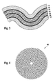
- a so-called stretching process can optionally be carried out, in which the composite body consisting of catalyst layer 12, solid electrolyte layer 14 and electrodes 16, 18 is subjected to, for example, short-term lateral expansion, resulting in a corrugated structure of the composite body. This is maintained in a subsequent heat treatment or sintering process, followed by an enlarged catalytically active surface of the resulting catalyst.
- FIG. 2 A further embodiment of a catalyst according to the present invention is disclosed in FIG. 2 shown.
- the composite consisting of catalyst layer 12, solid electrolyte layer 14 and the electrodes 16, 18 is laminated together before the heat or sintering treatment with another, similar composite body, wherein both composite bodies have common further electrodes 18.
- This composite consisting of two composite structures is then subjected to the heat or sintering treatment. It results in the FIG. 2 illustrated catalyst according to a second embodiment. If the overall structure consisting of two composite arrangements is subjected to a stretching process before the heat treatment or sintering treatment, the result is Sintering a catalyst according to a third embodiment, as in FIG. 3 is shown.
- the catalysts according to the first to third exemplary embodiments can furthermore be rolled up before the final heat treatment or sintering treatment about a rotation axis parallel to a longitudinal axis of the composite arrangement, so that a particularly cylindrical, three-dimensional catalyst body 40 is formed.
- This is provided, for example, after the final heat or sintering treatment with electrode contacts by the resulting, in particular cylindrical catalyst body 40, for example, each end ground and each end face is provided with a network of nickel or silver wire for contacting the first and second electrodes 16, 18.
- the mode of operation of the catalyst 10, 40 is based on the fact that in conventional catalysts according to the prior art, the oxygen released, for example, in the thermal decomposition of nitrogen oxides accumulates on the surface of the catalyst material and thus reduces the catalytic activity.
- a voltage is applied to the electrodes 16, 18 of the catalytic converter 10, 40 during operation, which leads to a pumping voltage of sufficient magnitude that oxygen from the at least one first electrode 16 to the at least one further electrode 18 in the form is transported by oxygen ions. If an exhaust gas atmosphere is present at the large area formed by the catalyst layer 12, the surface of the catalyst layer 12 depletes of gaseous oxygen, which favors the decomposition of oxygen-containing components of a combustion exhaust gas.
- the anode acting as at least one further electrode 18 is open-pored, so that the pumped to this oxygen can escape in a simple manner.
- the above-described catalyst according to the described embodiments is particularly suitable for the conversion of oxygen-containing Gas components of a combustion gas such as nitrogen oxides or sulfur oxides. It can be used both for the exhaust aftertreatment of combustion exhaust gases of internal combustion engines and for the exhaust gas treatment of heating systems or power plant applications.
- a combustion gas such as nitrogen oxides or sulfur oxides.
Landscapes
- Chemical & Material Sciences (AREA)
- Engineering & Computer Science (AREA)
- Chemical Kinetics & Catalysis (AREA)
- Combustion & Propulsion (AREA)
- Health & Medical Sciences (AREA)
- General Engineering & Computer Science (AREA)
- Mechanical Engineering (AREA)
- Toxicology (AREA)
- General Chemical & Material Sciences (AREA)
- Oil, Petroleum & Natural Gas (AREA)
- Environmental & Geological Engineering (AREA)
- Analytical Chemistry (AREA)
- Biomedical Technology (AREA)
- Electrochemistry (AREA)
- Catalysts (AREA)
- Exhaust Gas After Treatment (AREA)
- Physical Or Chemical Processes And Apparatus (AREA)
Abstract
Description
- Die vorliegende Erfindung bezieht sich auf einen Katalysator zur Behandlung von Verbrennungsabgasen, auf ein Verfahren zur Herstellung desselben sowie auf dessen Verwendung nach dem Oberbegriff der unabhängigen Ansprüche.
- Zur Nachbehandlung von Verbrennungsabgasen, welche beispielsweise bei industriellen Prozessen bzw. bei der motorischen Verbrennung von z. B. fossilen Brennstoffen entstehen, werden Katalysatoren eingesetzt. Diese dienen der Eliminierung gasförmiger Bestandteile der Verbrennungsabgase.
- Dabei gewinnt zunehmend die Eliminierung von Stickoxiden aus Abgasen von Verbrennungsmotoren an Bedeutung. Zu diesem Zweck werden unter anderem Stickoxidspeicherkatalysatoren eingesetzt, die zumindest temporär in einem Verbrennungsabgas enthaltene Stickoxide einspeichern und während eines nachfolgenden periodischen Regenerierungsvorgangs wieder freisetzen. Eine weitere Möglichkeit besteht in der Verwendung von Abgasnachbehandlungsvorrichtungen auf Basis der sogenannten SCR-Technologie (Selective Catalytic Reduction), bei der chemische Reduktionsmittel wie beispielsweise Ammoniak mit dem zu reinigenden Abgas vermischt und Stickoxide eliminiert werden können.
- Um die Eliminierungsrate eines derartigen Entstickungskatalysators zu optimieren, ist beispielsweise aus der
JP 07-275714 - Aufgabe der vorliegenden Erfindung ist es, einen Katalysator zur Behandlung von Verbrennungsabgasen zur Verfügung zu stellen, der effizient Stickoxide aus Verbrennungsabgasen zu entfernen vermag.
- Diese Aufgabe wird durch einen Katalysator bzw. durch ein Verfahren zu dessen Herstellung mit den kennzeichnenden Merkmalen der unabhängigen Ansprüche in vorteilhafter Weise gelöst. Dies beruht insbesondere darauf, dass der Katalysator eine flächige erste Elektrode aufweist, die in physischem Kontakt zu einer Schicht positioniert ist, die aus einem zur Umsetzung von Gaskomponenten des Verbrennungsabgases geeigneten katalytisch aktiven Material besteht. An diese flächige erste Elektrode kann eine elektrische Pumpspannung angelegt werden.
- Dies ermöglicht, dass der bei der Zersetzung - beispielsweise von Stickoxid - entstehende Sauerstoff in Form von O2- - Ionen elektrochemisch aus dem Bereich der Schicht, die aus einem zur Umsetzung von Gaskomponenten des Verbrennungsabgases geeigneten katalytisch aktiven Material besteht, entfernt wird. Auf diese Weise wird eine niedrige Sauerstoffkonzentration im Bereich dieser Schicht realisiert und das katalytisch aktive Material wird vor einer sauerstoffbedingten Deaktivierung wirksam geschützt.
- Weitere vorteilhafte Ausführungsformen des vorliegenden Katalysators ergeben sich aus den Unteransprüchen.
- So ist von Vorteil, wenn eine weitere Elektrode, die als Gegenelektrode zu der ersten Elektrode fungiert, mit dieser eine elektrochemische Zelle bildet und offen porös ausgeführt ist. Auf diese Weise kann der bei der Zersetzung von Stickoxiden freigesetzte Sauerstoff anodenseitig auf einfache Weise durch die offenporige Struktur der Elektrode abgeführt werden.
- Weiterhin ist von Vorteil, wenn die das katalytisch aktive Material enthaltende Katalysatorschicht eine gewellte Struktur aufweist. Dies kann beispielsweise durch eine laterale kurzzeitige Streckung eines als keramischer Grünkörper vorliegenden Verbundes aus Katalysatorschicht, der ersten und zweiten Elektrode sowie eines Festelektrolyten erzeugt werden. Die gewellte Struktur hat den Vorteil einer Stabilitätszunahme bei gleichzeitiger Vergrößerung der reaktiven und zur Umsetzung von Abgasbestandteilen zur Verfügung stehenden Oberfläche des erfindungsgemäßen Katalysators.
- Gemäß einer besonders vorteilhaften Ausführungsform der vorliegenden Erfindung wird ein Verbund aus einem Festelektrolyten, der ersten und zweiten Elektrode sowie einer Katalysatorschicht nach einer kurzzeitigen lateralen Dehnung parallel zu einer Längsachse des Grünkörpers unter Ausbildung eines rotationssymmetrischen Körpers aufgerollt. Auf diese Weise kann in einfacher Weise die endgültige dreidimensionale Form des Katalysators erzeugt werden.
- Gemäß einer weiteren vorteilhaften Ausführungsform der vorliegenden Erfindung sind im Bereich der Katalysatorschicht mehrere erste Elektroden und mehrere zweite Elektroden vorgesehen, die zusammen eine Interdigitalstruktur bilden. Diese Interdigitalstruktur ermöglicht eine einfache gemeinsame Kontaktierung, jeweils für alle ersten Elektroden bzw. für alle zweiten Elektroden mittels einer gemeinsamen elektrischen Zuleitung, beispielsweise stirnseitig an dem erzeugten rotationssymmetrischen Katalysatorkörper. Weitere vorteilhafte Ausführungsformen des vorliegenden Katalysators ergeben sich aus den Unteransprüchen.
- Eine Ausführungsform der vorliegenden Erfindung ist in der Zeichnung dargestellt und in der sich anschließenden Beschreibung näher erläutert. Es zeigt
- Figur 1
- eine schematische Schnittdarstellung eines Katalysators zur Behandlung von Verbrennungsabgasen gemäß einer ersten Ausführungsform der vorliegenden Erfindung,
- Figur 2
- eine schematische Schnittdarstellung eines Katalysators zur Behandlung von Verbrennungsabgasen gemäß einer zweiten Ausführungsform der vorliegenden Erfindung
- Figur 3
- eine schematische Schnittdarstellung des in
Figur 2 dargestellten Katalysators, wobei dieser mit einer gewellten Struktur versehen ist und - Figur 4
- eine schematische Schnittdarstellung eines Katalysators gemäß einem der vorgenannten Ausführungsbeispiele als rotationssymmetrischer Katalysatorkörper.
- In
Figur 1 ist schematisch ein der Erfindung zugrundeliegender Katalysator zur Behandlung von Verbrennungsabgasen dargestellt. Dieser dient vorzugsweise der Umsetzung von gasförmigen bzw. festen Schadstoffbestandteilen der Verbrennungsabgase, insbesondere der Umsetzung von sauerstoffhaltigen gasförmigen Komponenten. Dabei umfasst der Katalysator 10 eine Katalysatorschicht 12 eines katalytisch aktiven Materials und ist vorzugsweise von einer Festelektrolytschicht 14 bedeckt. Als Festelektrolyt eignet sich beispielsweise mit Yttriumoxid teil- bzw. vollstabilisiertes Zirkoniumdioxid, Bi2O3 oder Gd-dotiertes CeO2. Darüber hinaus sind beispielsweise auf einer weiteren Großfläche der Katalysatorschicht 12 eine oder mehrere erste Elektroden 16 positioniert. Die mindestens eine erste Elektrode 16 bildet zusammen mit mindestens einer zweiten Elektrode 18, die vorzugsweise auf der der Schicht 12 abgewandten Seite der Festelektrolytschicht 14 positioniert ist, eine elektrochemische Zelle. Dabei sind beispielsweise die Elektroden 16, 18 aus Nickel, Silber, Platin oder Palladium bzw. aus Legierungen dieser Elemente gefertigt. - Als katalytisch aktive Komponenten der Katalysatorschicht 12 eignen sich beispielsweise metallische Komponenten wie Rhodium, Palladium, Platin, Iridium oder Nickel bzw. Legierungen derselben. Diese metallischen Komponenten können beispielsweise als nanoskalige Dispersion auf der Oberfläche von Zirkoniumdioxidpartikeln vorliegen. Des weiteren eignen sich als katalytisch aktive Komponenten der Katalysatorschicht 12 Mischoxide wie insbesondere Spinelle der allgemeinen Formel A2BO4 sowie Perowskite der allgemeinen Formel ABO3, wobei A beispielsweise für Elemente der Lanthaniden, Actiniden, der Alkalimetalle, der Erdalkalimetalle oder für Yttrium steht und B für Kupfer, Eisen, Nickel oder Kobalt. Dabei können die A- bzw. B-Positionen der genannten Verbindungen gegebenenfalls auch unstöchiometrisch jeweils durch mehrere der vorgenannten Elemente belegt sein. Besonders bevorzugt sind Perowskite, bei denen die A-Position mit den Elementen Lanthan oder Strontium belegt sind und die B-Positionen mit mindestens einem der Elemente Eisen, Kobalt oder Nickel. Beispielhafte Vertreter dieser geeigneten Perowskite sind (La0,9Sr0,1)(Fe0,9Ni0,1)O3, (La0,9Sr0,1)FeO3 oder La0,5Sr0,5CoO3; die Verbindung LaNiO3 ist aus technischen Gründen eher ungeeignet.
- Zur Herstellung eines Katalysators gemäß dem in
Figur 1 dargestellten ersten Ausführungsbeispiel wird vorzugsweise zunächst eine Folie eines keramischen Festelektrolytmaterials als Grünkörper vorgelegt und diese auf einer ersten Großfläche mit mindestens einer ersten Elektrode 16 und auf einer gegenüberliegenden weiteren Großfläche mit mindestens einer weiteren Elektrode 18 bedruckt wird. Daran anschließend wird die mit der mindestens einen ersten Elektrode 16 versehene Großfläche der Festelektrolytschicht 14 mit der Katalysatorschicht 12 versehen. - Die Elektroden 16, 18 werden vorzugsweise in Form einer Interdigitalstruktur aufgebracht. Dazu werden die Elektroden 16, 18 beispielsweise in Form mehrerer, insbesondere paralleler, metallischer Streifen ausgeführt, wobei beispielsweise die ersten Elektroden 16 bis in unmittelbare Nähe einer ersten Stirnseite des entstehenden Schichtverbunds geführt werden; dabei weisen die ersten Elektroden 16 zur gegenüberliegenden Stirnseite des Schichtverbundes einen Mindestabstand von 1 bis 4 mm auf. Die weiteren Elektroden 18 sind gegenläufig orientiert; sie halten zur ersten Stirnfläche des Schichtverbundes einen Mindestabstand von 1 bis 4 mm ein und grenzen im Wesentlichen unmittelbar an die gegenüberliegende Stirnfläche des Schichtverbundes. Diese Maßnahme erlaubt eine besonders einfache Kontaktierung der ersten bzw. weiteren Elektroden 16, 18, indem an der ersten Stirnfläche des Schichtverbundes eine ausschließliche Kontaktierung der ersten Elektroden 16 erfolgt und an der gegenüberliegenden Stirnseite eine ausschließliche Kontaktierung der weiteren Elektroden 18. Der auf diese Weise erzeugte Schichtverbund wird einer Wärmebehandlung, insbesondere Sinterbehandlung, unterzogen unter Ausbildung der in
Figur 1 dargestellten Katalysatorstruktur. - Vor der Wärmebehandlung kann jedoch optional ein sogenannter Reckprozess durchgeführt werden, bei dem der aus Katalysatorschicht 12, Festelektrolytschicht 14 sowie Elektroden 16, 18 bestehende Verbundkörper einer beispielsweise kurzzeitigen lateralen Dehnung unterworfen wird, sodass eine gewellte Struktur des Verbundkörpers resultiert. Diese bleibt bei einem nachfolgenden Wärmebehandlungs- bzw. Sinterprozess erhalten, wobei eine vergrößerte katalytisch wirksame Oberfläche des resultierenden Katalysators folgt.
- Eine weitere Ausführungsform eines Katalysators gemäß vorliegender Erfindung ist in
Figur 2 dargestellt. Dabei bezeichnen gleiche Bezugszeichen gleiche Bauteilkomponenten wie in den vorhergehenden Abbildungen. Der aus Katalysatorschicht 12, Festelektrolytschicht 14 und den Elektroden 16, 18 bestehende Verbundkörper wird vor der Wärme- bzw. Sinterbehandlung mit einem weiteren, gleichartigen Verbundkörper zusammenlaminiert, wobei beide Verbundkörper gemeinsame weitere Elektroden 18 aufweisen. Diese aus zwei Verbundanordnungen bestehende Gesamtstruktur wird dann der Wärme- bzw. Sinterbehandlung unterworfen. Es resultiert der inFigur 2 dargestellte Katalysator gemäß einer zweiten Ausführungsform. Wird die aus zwei Verbundanordnungen bestehende Gesamtstruktur vor der Wärme- bzw. Sinterbehandlung einem Reckprozess unterworfen, so resultiert nach dem Sintern ein Katalysator gemäß einer dritten Ausführungsform, wie er inFigur 3 dargestellt ist. - Die Katalysatoren gemäß erstem bis drittem Ausführungsbeispiel können darüber hinaus vor der abschließenden Wärme- bzw. Sinterbehandlung um eine zu einer Längsachse der Verbundanordnung parallele Drehachse aufgerollt werden, sodass ein insbesondere zylindrischer, dreidimensionaler Katalysatorkörper 40 entsteht. Dieser wird beispielsweise nach der abschließenden Wärme- bzw. Sinterbehandlung mit Elektrodenkontaktierungen versehen, indem der resultierende, insbesondere zylindrische Katalysatorkörper 40 beispielsweise stirnseitig jeweils angeschliffen wird und jeweils stirnseitig mit einem Netz eines Nickel- bzw. Silberdrahtes versehen wird zur Kontaktierung der ersten bzw. zweiten Elektroden 16, 18.
- Die Funktionsweise des Katalysators 10, 40 beruht darauf, dass bei üblichen Katalysatoren gemäß Stand der Technik, der beispielsweise bei der thermischen Spaltung von Stickoxiden frei werdende Sauerstoff sich an der Oberfläche des Katalysatormaterials anlagert und so die katalytische Aktivität herabsetzt. Um dies zu verhindern, wird im Betrieb an die Elektroden 16, 18 des Katalysators 10, 40 eine Spannung angelegt, die als Pumpspannung in ausreichender Höhe dazu führt, dass Sauerstoff von der mindestens einen ersten Elektrode 16 zu der mindestens einen weiteren Elektrode 18 in Form von Sauerstoffionen transportiert wird. Liegt an der durch die Katalysatorschicht 12 gebildeten Großfläche eine Abgasatmosphäre an, so verarmt die Oberfläche der Katalysatorschicht 12 an gasförmigem Sauerstoff, wodurch die Zersetzung von sauerstoffhaltigen Komponenten eines Verbrennungsabgases begünstigt wird.
- Weiterhin wird einer Deaktivierung der in der Katalysatorschicht 12 vorgesehenen katalytisch aktiven Komponenten vorgebeugt. Dabei ist von Vorteil, wenn die als Anode fungierende mindestens eine weitere Elektrode 18 offenporig ausgeführt ist, sodass der zu dieser gepumpte Sauerstoff auf einfache Weise entweichen kann.
- Der vorbeschriebene Katalysator gemäß der beschriebenen Ausführungsformen eignet sich insbesondere zur Umsetzung von sauerstoffhaltigen Gaskomponenten eines Verbrennungsgases wie Stickoxiden oder Schwefeloxiden. Er kann sowohl zur Abgasnachbehandlung von Verbrennungsabgasen von Verbrennungsmotoren herangezogen werden als auch zur Abgasbehandlung von Heizanlagen oder Kraftwerksanwendungen.
Claims (12)
- Katalysator zur Behandlung von Verbrennungsabgasen mit einer ersten dem zu reinigenden Abgas ausgesetzten Großfläche, die eine Schicht aus einem zur Umsetzung von Gaskomponenten geeigneten katalytisch aktiven Material aufweist, dadurch gekennzeichnet, dass eine flächige erste Elektrode (16) in physischem Kontakt mit der Schicht (12) aus einem zur Umsetzung von Gaskomponenten geeigneten katalytisch aktiven Material positioniert ist, wobei an die flächige erste Elektrode (16) eine elektrische Pumpspannung anlegbar ist.
- Katalysator nach Anspruch 1, dadurch gekennzeichnet, dass eine Festelektrolytschicht (14) vorgesehen ist, die mit der ersten Elektrode (16) und/oder einer weiteren Elektrode (18) in physischem Kontakt steht, wobei die erste und die weitere Elektrode (16, 18) eine elektrochemische Zelle bildet.
- Katalysator nach Anspruch 1 oder 2, dadurch gekennzeichnet, dass die weitere Elektrode (18) als Anode fungiert und offenporig ausgeführt ist.
- Katalysator nach einem der Ansprüche 1 bis 3, dadurch gekennzeichnet, dass die Festelektrolytschicht Zirkoniumdioxid enthält.
- Katalysator nach einem der vorhergehenden Ansprüche, dadurch gekennzeichnet, dass das Katalysatormaterial ein Spinell oder einen Perowskit umfasst.
- Katalysator nach Anspruch 5, dadurch gekennzeichnet, dass der Perowskit eine Verbindung der allgemeinen Formel ABO3 ist und der Spinell eine Verbindung der allgemeinen Formel A2BO4, wobei A für Yttrium oder mindestens ein Element der Lanthanide, Actinide, der Alkalimetalle oder der Erdalkalimetalle sowie für Mischungen der genannten Elemente steht, und B für mindestens eines der Elemente Kupfer, Eisen, Cobalt, Nickel oder Mischungen der genannten Elemente steht.
- Katalysator nach einem der vorhergehenden Ansprüche, dadurch gekennzeichnet, dass die Schicht (12) aus einem zur Umsetzung von Gaskomponenten geeigneten katalytisch aktiven Material eine gewellte Struktur aufweist.
- Katalysator nach einem der vorhergehenden Ansprüche, dadurch gekennzeichnet, dass mehrere erste und mehrere weitere Elektroden (16, 18) vorgesehen sind, die miteinander eine Interdigitalstruktur ausbilden.
- Verfahren zur Herstellung eines Katalysators zur Behandlung von Verbrennungsabgasen, insbesondere eines Katalysators nach einem der Ansprüche 1 bis 8, wobei eine ein Festelektrolytmaterial umfassende keramische Grünkörperfolie auf einer ersten Großfläche mit einer ersten Elektrode und mit einer ein zur Umsetzung von Gaskomponenten geeignetes katalytisch aktives Material enthaltenden Schicht versehne wird und auf ihrer zweiten Großfläche mit einer zweiten Elektrode versehen wird, dadurch gekennzeichnet, dass der Verbund aus keramischer Grünkörperfolie, erster und zweiter Elektrode (16, 18) und der Schicht (12) aus einem zur Umsetzung von Gaskomponenten geeigneten katalytisch aktiven Material lateral gedehnt wird, sodass eine wellige Struktur resultiert.
- Verfahren nach Anspruch 9, dadurch gekennzeichnet, dass der Verbund aus keramischer Grünkörperfolie, erster und zweiter Elektrode (16, 18) und der Schicht (12) aus einem zur Umsetzung von Gaskomponenten geeigneten katalytisch aktiven Material nach der lateralen Dehnung parallel zu einer Längsachse der Grünkörperfolie unter Ausbildung eines rotationssymmetrischen Körpers (40) aufgerollt wird.
- Verfahren nach Anspruch 9 oder 10, dadurch gekennzeichnet, dass abschließend eine Sinterbehandlung des Verbundes aus keramischer Grünkörperfolie, erster und zweiter Elektrode (16, 18) und der Schicht (12) aus einem zur Umsetzung von Gaskomponenten geeigneten katalytisch aktiven Material erfolgt.
- Verwendung eines Katalysators nach einem der Ansprüche 1 bis 8 zur Entfernung sauerstoffhaltiger Komponenten eines Gasgemischs.
Applications Claiming Priority (1)
| Application Number | Priority Date | Filing Date | Title |
|---|---|---|---|
| DE102007062249A DE102007062249A1 (de) | 2007-12-21 | 2007-12-21 | Katalysator zur Behandlung von Verbrennungsabgasen |
Publications (2)
| Publication Number | Publication Date |
|---|---|
| EP2072770A2 true EP2072770A2 (de) | 2009-06-24 |
| EP2072770A3 EP2072770A3 (de) | 2010-04-07 |
Family
ID=40545845
Family Applications (1)
| Application Number | Title | Priority Date | Filing Date |
|---|---|---|---|
| EP08105658A Withdrawn EP2072770A3 (de) | 2007-12-21 | 2008-10-24 | Katalysator zur Behandlung von Verbrennungsabgasen |
Country Status (3)
| Country | Link |
|---|---|
| US (1) | US20090241514A1 (de) |
| EP (1) | EP2072770A3 (de) |
| DE (1) | DE102007062249A1 (de) |
Cited By (2)
| Publication number | Priority date | Publication date | Assignee | Title |
|---|---|---|---|---|
| FR2939696A1 (fr) * | 2008-12-17 | 2010-06-18 | Saint Gobain Ct Recherches | Structure de purification incorporant un systeme de catalyse electrochimique polarise |
| WO2011160895A1 (de) * | 2010-06-23 | 2011-12-29 | Robert Bosch Gmbh | Elektrochemischer stickoxidkatalysator |
Families Citing this family (3)
| Publication number | Priority date | Publication date | Assignee | Title |
|---|---|---|---|---|
| DE102008026178A1 (de) * | 2008-05-30 | 2009-12-03 | Deutz Ag | SCR-Katalysator mit hohem Wirkungsgrad |
| TWI548780B (zh) * | 2014-07-02 | 2016-09-11 | 黃大勇 | Electrochemical dual battery panels and devices for controlling exhaust emissions |
| US11110432B2 (en) * | 2019-12-09 | 2021-09-07 | Toyota Motor Engineering And Manufacturing North America, Inc. | Multi-transition metal doped copper-cobalt spinel catalyst material for NOx decomposition |
Citations (1)
| Publication number | Priority date | Publication date | Assignee | Title |
|---|---|---|---|---|
| JPH07275714A (ja) | 1994-04-11 | 1995-10-24 | Toray Ind Inc | NOx除去装置 |
Family Cites Families (11)
| Publication number | Priority date | Publication date | Assignee | Title |
|---|---|---|---|---|
| SE404065B (sv) * | 1972-11-30 | 1978-09-18 | Atomic Energy Authority Uk | Apparat for katalytisk rening av avgaser samt katalysator |
| JPH03224634A (ja) * | 1990-01-30 | 1991-10-03 | Cataler Kogyo Kk | ヒータ付オゾン分解用触媒 |
| ES2091812T3 (es) * | 1990-10-10 | 1996-11-16 | Constantin G Vayenas | Uso de catalizadores electroliticos de metal solido. |
| DE69311832T2 (de) * | 1992-04-14 | 1997-10-16 | Toyoda Chuo Kenkyusho Kk | Verfahren zur Reduktion von Stickoxiden |
| US5401372A (en) * | 1993-04-26 | 1995-03-28 | Ceramatec, Inc. | Electrochemical catalytic reduction cell for the reduction of NOx in an O2 -containing exhaust emission |
| JP2636193B2 (ja) * | 1994-12-14 | 1997-07-30 | 工業技術院長 | 排気ガスの処理方法 |
| DE19900967A1 (de) * | 1999-01-13 | 2000-07-20 | Volkswagen Ag | Vorrichtung zur Reinigung des Abgases einer Brennkraftmaschine |
| DE19904068A1 (de) * | 1999-02-02 | 2000-08-03 | Volkswagen Ag | Vorrichtung zur Reinigung des Abgases einer Brennkraftmaschine |
| JP3657542B2 (ja) * | 2001-07-24 | 2005-06-08 | 独立行政法人産業技術総合研究所 | 化学反応器 |
| JP2007014873A (ja) * | 2005-07-07 | 2007-01-25 | Honda Motor Co Ltd | 粒子状物質浄化装置 |
| DE102005043196A1 (de) * | 2005-09-09 | 2007-03-15 | Emitec Gesellschaft Für Emissionstechnologie Mbh | Verfahren zur Herstellung eines ringförmigen Wabenkörpers, sowie ringförmiger Wabenkörper |
-
2007
- 2007-12-21 DE DE102007062249A patent/DE102007062249A1/de not_active Withdrawn
-
2008
- 2008-10-24 EP EP08105658A patent/EP2072770A3/de not_active Withdrawn
- 2008-12-11 US US12/333,087 patent/US20090241514A1/en not_active Abandoned
Patent Citations (1)
| Publication number | Priority date | Publication date | Assignee | Title |
|---|---|---|---|---|
| JPH07275714A (ja) | 1994-04-11 | 1995-10-24 | Toray Ind Inc | NOx除去装置 |
Cited By (3)
| Publication number | Priority date | Publication date | Assignee | Title |
|---|---|---|---|---|
| FR2939696A1 (fr) * | 2008-12-17 | 2010-06-18 | Saint Gobain Ct Recherches | Structure de purification incorporant un systeme de catalyse electrochimique polarise |
| WO2010076508A1 (fr) * | 2008-12-17 | 2010-07-08 | Saint-Gobain Centre De Recherches Et D'etudes Europeen | Structure de purification incorporant un systeme de catalyse electrochimique polarise |
| WO2011160895A1 (de) * | 2010-06-23 | 2011-12-29 | Robert Bosch Gmbh | Elektrochemischer stickoxidkatalysator |
Also Published As
| Publication number | Publication date |
|---|---|
| EP2072770A3 (de) | 2010-04-07 |
| DE102007062249A1 (de) | 2009-06-25 |
| US20090241514A1 (en) | 2009-10-01 |
Similar Documents
| Publication | Publication Date | Title |
|---|---|---|
| DE3786943T2 (de) | Gasdurchlässige Elektrode. | |
| DE60118884T2 (de) | Verfahren zur herstellung einer anoden-tragenden elektrolyt enthaltende anordnung und solche anordnung enthaltende keramische zelle | |
| DE10007448B4 (de) | Aktivierte Kathode und Verfahren zu ihrer Herstellung | |
| DE112007000948T5 (de) | Abgasreinigungssystem und Verfahren zum Reinigen von Abgasen | |
| DE112015001452B4 (de) | Sauerstoffreduktionskatalysator und Herstellungsverfahren dafür | |
| DE7638054U1 (de) | Elektrochemische zelle | |
| DE19949431A1 (de) | Festoxidbrennstoffzelle mit einem Mischungsgradienten zwischen Elektrode und Elektrolyt | |
| DE69311832T2 (de) | Verfahren zur Reduktion von Stickoxiden | |
| DE1596223C3 (de) | Gasdichter alkalischer Kadmium-Nickel- oder Kadmium-Silber-Akkumulator, bei dem zwischen Scheider und negativer Elektrode eine elektrisch leitfähige poröse Schicht angeordnet ist | |
| EP2072770A2 (de) | Katalysator zur Behandlung von Verbrennungsabgasen | |
| WO2019215309A1 (de) | Elektrochemischer reaktor und verfahren zum erzeugen von ammoniak und wasserstoff aus einer harnstofflösung durch elektrolyse | |
| DE112005001378T5 (de) | Ausgedehnte Elektroden für PEM-Brennstoffzellen-Anwendungen | |
| DE102004024026A1 (de) | Katalysator zur N2O-Zersetzung beim Ostwaldprozess | |
| DE60123839T2 (de) | Gestapelte mikrostrukturen leitender, keramischer oxidionenmembranen; verwendung zur trennung von sauerstoff von luft | |
| DE4417403C2 (de) | Verfahren zur Herstellung einer Gaselektrode | |
| EP0988654A1 (de) | Doppelschichtkathode für schmelzkarbonatbrennstoffzellen und verfahren zur herstellung einer solchen | |
| DE19651492B4 (de) | Vorrichtung zur NOx-Entfernung aus dem Abgas von Verbrennungsmotoren | |
| DE102015107770A1 (de) | Verfahren und Vorrichtung zur Zersetzung von Stickstoffoxid | |
| EP1586365B1 (de) | Verwendung eines Katalysators zur Zersetzung von Distickstoffmonoxid (N2O) beim Ostwaldprozess | |
| DE112021007166T5 (de) | Brennstoffelektrode und elektrochemische zelle | |
| DE102015110488A1 (de) | Elektrochemische Doppelzellen-Platte und Vorrichtung zur Abgasemmisions-Regelung von Fahrzeugen | |
| DE112010005261B4 (de) | Platin-Nanopartikel mit hohlen Skelettstrukturen und Herstellungsverfahren | |
| EP1915793B1 (de) | Schutz anodengestützter hochtemperaturbrennstoffzellen gegen reoxidation der anode | |
| DE10392987T5 (de) | Chemisches Reaktionssystem des galvanischen Zellentyps, Verfahren zur Aktivierung dieses und Verfahren zur Reaktion | |
| DE102008036370A1 (de) | Sensor-integrierte Vorrichtung |
Legal Events
| Date | Code | Title | Description |
|---|---|---|---|
| PUAI | Public reference made under article 153(3) epc to a published international application that has entered the european phase |
Free format text: ORIGINAL CODE: 0009012 |
|
| AK | Designated contracting states |
Kind code of ref document: A2 Designated state(s): AT BE BG CH CY CZ DE DK EE ES FI FR GB GR HR HU IE IS IT LI LT LU LV MC MT NL NO PL PT RO SE SI SK TR |
|
| AX | Request for extension of the european patent |
Extension state: AL BA MK RS |
|
| RIN1 | Information on inventor provided before grant (corrected) |
Inventor name: SCHOTT, FLORIAN Inventor name: MENESKLOU, WOLFGANG Inventor name: BOCKHORN, HENNING Inventor name: KURETI, SVEN Inventor name: EISELE, ULRICH Inventor name: SATET, RAPHAELLE Inventor name: MATTERN, ANDREAS Inventor name: GERNSBECK, MATTHIAS |
|
| RIC1 | Information provided on ipc code assigned before grant |
Ipc: B01D 53/94 20060101ALI20091028BHEP Ipc: B01D 53/32 20060101ALI20091028BHEP Ipc: F01N 3/20 20060101ALI20091028BHEP Ipc: F01N 3/08 20060101ALI20091028BHEP Ipc: F01N 3/01 20060101AFI20090420BHEP |
|
| PUAL | Search report despatched |
Free format text: ORIGINAL CODE: 0009013 |
|
| AK | Designated contracting states |
Kind code of ref document: A3 Designated state(s): AT BE BG CH CY CZ DE DK EE ES FI FR GB GR HR HU IE IS IT LI LT LU LV MC MT NL NO PL PT RO SE SI SK TR |
|
| AX | Request for extension of the european patent |
Extension state: AL BA MK RS |
|
| RIC1 | Information provided on ipc code assigned before grant |
Ipc: F01N 3/28 20060101ALI20100226BHEP Ipc: B01D 53/94 20060101ALI20100226BHEP Ipc: B01D 53/32 20060101ALI20100226BHEP Ipc: F01N 3/20 20060101ALI20100226BHEP Ipc: F01N 3/08 20060101ALI20100226BHEP Ipc: F01N 3/01 20060101AFI20090420BHEP |
|
| AKY | No designation fees paid | ||
| STAA | Information on the status of an ep patent application or granted ep patent |
Free format text: STATUS: THE APPLICATION IS DEEMED TO BE WITHDRAWN |
|
| 18D | Application deemed to be withdrawn |
Effective date: 20101008 |
|
| REG | Reference to a national code |
Ref country code: DE Ref legal event code: R108 Effective date: 20110322 Ref country code: DE Ref legal event code: 8566 |