EP2072779A2 - Gebläsegondelströmungssteuerung und Verfahren zur Steuerung der Grenzschicht an dem Eingang einer Gebläsegondel - Google Patents
Gebläsegondelströmungssteuerung und Verfahren zur Steuerung der Grenzschicht an dem Eingang einer Gebläsegondel Download PDFInfo
- Publication number
- EP2072779A2 EP2072779A2 EP08253893A EP08253893A EP2072779A2 EP 2072779 A2 EP2072779 A2 EP 2072779A2 EP 08253893 A EP08253893 A EP 08253893A EP 08253893 A EP08253893 A EP 08253893A EP 2072779 A2 EP2072779 A2 EP 2072779A2
- Authority
- EP
- European Patent Office
- Prior art keywords
- ring
- fan
- nacelle
- gas turbine
- fan nacelle
- Prior art date
- Legal status (The legal status is an assumption and is not a legal conclusion. Google has not performed a legal analysis and makes no representation as to the accuracy of the status listed.)
- Granted
Links
Images

Classifications
-
- F—MECHANICAL ENGINEERING; LIGHTING; HEATING; WEAPONS; BLASTING
- F02—COMBUSTION ENGINES; HOT-GAS OR COMBUSTION-PRODUCT ENGINE PLANTS
- F02C—GAS-TURBINE PLANTS; AIR INTAKES FOR JET-PROPULSION PLANTS; CONTROLLING FUEL SUPPLY IN AIR-BREATHING JET-PROPULSION PLANTS
- F02C7/00—Features, components parts, details or accessories, not provided for in, or of interest apart form groups F02C1/00 - F02C6/00; Air intakes for jet-propulsion plants
- F02C7/04—Air intakes for gas-turbine plants or jet-propulsion plants
- F02C7/042—Air intakes for gas-turbine plants or jet-propulsion plants having variable geometry
-
- B—PERFORMING OPERATIONS; TRANSPORTING
- B64—AIRCRAFT; AVIATION; COSMONAUTICS
- B64D—EQUIPMENT FOR FITTING IN OR TO AIRCRAFT; FLIGHT SUITS; PARACHUTES; ARRANGEMENT OR MOUNTING OF POWER PLANTS OR PROPULSION TRANSMISSIONS IN AIRCRAFT
- B64D33/00—Arrangement in aircraft of power plant parts or auxiliaries not otherwise provided for
- B64D33/02—Arrangement in aircraft of power plant parts or auxiliaries not otherwise provided for of combustion air intakes
-
- F—MECHANICAL ENGINEERING; LIGHTING; HEATING; WEAPONS; BLASTING
- F02—COMBUSTION ENGINES; HOT-GAS OR COMBUSTION-PRODUCT ENGINE PLANTS
- F02C—GAS-TURBINE PLANTS; AIR INTAKES FOR JET-PROPULSION PLANTS; CONTROLLING FUEL SUPPLY IN AIR-BREATHING JET-PROPULSION PLANTS
- F02C7/00—Features, components parts, details or accessories, not provided for in, or of interest apart form groups F02C1/00 - F02C6/00; Air intakes for jet-propulsion plants
- F02C7/04—Air intakes for gas-turbine plants or jet-propulsion plants
- F02C7/057—Control or regulation
-
- B—PERFORMING OPERATIONS; TRANSPORTING
- B64—AIRCRAFT; AVIATION; COSMONAUTICS
- B64D—EQUIPMENT FOR FITTING IN OR TO AIRCRAFT; FLIGHT SUITS; PARACHUTES; ARRANGEMENT OR MOUNTING OF POWER PLANTS OR PROPULSION TRANSMISSIONS IN AIRCRAFT
- B64D33/00—Arrangement in aircraft of power plant parts or auxiliaries not otherwise provided for
- B64D33/02—Arrangement in aircraft of power plant parts or auxiliaries not otherwise provided for of combustion air intakes
- B64D2033/0226—Arrangement in aircraft of power plant parts or auxiliaries not otherwise provided for of combustion air intakes comprising boundary layer control means
-
- F—MECHANICAL ENGINEERING; LIGHTING; HEATING; WEAPONS; BLASTING
- F05—INDEXING SCHEMES RELATING TO ENGINES OR PUMPS IN VARIOUS SUBCLASSES OF CLASSES F01-F04
- F05D—INDEXING SCHEME FOR ASPECTS RELATING TO NON-POSITIVE-DISPLACEMENT MACHINES OR ENGINES, GAS-TURBINES OR JET-PROPULSION PLANTS
- F05D2270/00—Control
- F05D2270/01—Purpose of the control system
- F05D2270/10—Purpose of the control system to cope with, or avoid, compressor flow instabilities
- F05D2270/101—Compressor surge or stall
- F05D2270/102—Compressor surge or stall caused by working fluid flow velocity profile distortion
- F05D2270/1022—Compressor surge or stall caused by working fluid flow velocity profile distortion due to high angle of attack of aircraft
-
- F—MECHANICAL ENGINEERING; LIGHTING; HEATING; WEAPONS; BLASTING
- F05—INDEXING SCHEMES RELATING TO ENGINES OR PUMPS IN VARIOUS SUBCLASSES OF CLASSES F01-F04
- F05D—INDEXING SCHEME FOR ASPECTS RELATING TO NON-POSITIVE-DISPLACEMENT MACHINES OR ENGINES, GAS-TURBINES OR JET-PROPULSION PLANTS
- F05D2270/00—Control
- F05D2270/01—Purpose of the control system
- F05D2270/17—Purpose of the control system to control boundary layer
-
- Y—GENERAL TAGGING OF NEW TECHNOLOGICAL DEVELOPMENTS; GENERAL TAGGING OF CROSS-SECTIONAL TECHNOLOGIES SPANNING OVER SEVERAL SECTIONS OF THE IPC; TECHNICAL SUBJECTS COVERED BY FORMER USPC CROSS-REFERENCE ART COLLECTIONS [XRACs] AND DIGESTS
- Y02—TECHNOLOGIES OR APPLICATIONS FOR MITIGATION OR ADAPTATION AGAINST CLIMATE CHANGE
- Y02T—CLIMATE CHANGE MITIGATION TECHNOLOGIES RELATED TO TRANSPORTATION
- Y02T50/00—Aeronautics or air transport
- Y02T50/60—Efficient propulsion technologies, e.g. for aircraft
Definitions
- This disclosure relates to a fan nacelle for a gas turbine engine and an associated flow control device.
- Gas turbine engines for commercial aircraft applications typically include an engine core housed within a core nacelle.
- the core drives a large fan upstream from the core that provides airflow into the core.
- a significant portion of airflow bypasses the core to provide thrust.
- One or more spools are arranged within the core, and a gear train may be provided between one of the spools and the fan.
- a fan case and fan nacelle surround the fan and at least a portion of the core.
- the performance of a turbofan engine varies during diversified conditions experienced by the aircraft.
- An inlet lip portion located at the foremost end of the fan nacelle is typically designed to enable operation of the turbofan engine and reduce the separation of airflow from the inlet lip of the nacelle assembly during these diversified conditions.
- the inlet lip requires a "thick" inlet lip to support operation of the engine during specific flight conditions, such as cross-wind conditions, take-off and the like.
- the thick inlet lip may reduce the efficiency of the turbofan engine during normal cruise conditions of the aircraft.
- the maximum diameter of the fan nacelle may be approximately 10-20% larger than required during cruise conditions.
- boundary layer separation is a common problem associated with thick inlet lip. Boundary layer separation occurs where airflow communicated through the inlet lip separates from an inner surface of the inlet lip portion, which may cause engine stall, the loss of the capability to generate lift, and may decrease engine efficiency.
- This disclosure relates to a gas turbine engine including a core engine that drives a fan.
- a fan nacelle surrounds the fan and provides an inner surface facing the fan.
- the fan nacelle includes an inlet lip adjoining the inner surface.
- a ring is arranged at the inner surface and is axially upstream from the fan.
- the ring includes a deployed position in which the ring is spaced radially inwardly from the inner surface to provide a gap therebetween through which air flows.
- the ring also includes a stowed position in which the ring is arranged radially inwardly from the deployed position and proximate to the inner surface.
- the ring is commanded to the deployed position in response to detecting a first condition, which corresponds to a flow separation condition at the fan nacelle inlet.
- the ring may be stowed during cruise conditions, for example.
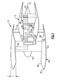
- FIG. 1 An engine 10 with geared architecture is shown in Figure 1 .
- a pylon typically secures the engine 10 to an aircraft.
- the engine 10 includes a core nacelle 12 that surrounds a low spool 14 and high spool 24 that are rotatable about a common axis A.
- the low spool 14 supports a low pressure compressor 16 and low pressure turbine 18.
- the low spool 14 drives a fan 20 through a gear train 22.
- the high spool 24 supports a high pressure compressor 26 and high pressure turbine 28.
- a combustor 30 is arranged between the high pressure compressor 26 and high pressure turbine 28. Compressed air from compressors 16, 26 mixes with fuel from the combustor 30 and is expanded in turbines 18, 28.
- the engine 10 is a high bypass turbofan arrangement.
- the bypass ratio is greater than 10
- the turbofan diameter is substantially larger than the diameter of the low pressure compressor 16.
- the low pressure turbine 18 has a pressure ratio that is greater than 5:1, in one example.
- the gear train 22 is an epicycle gear train, for example, a star gear train, providing a gear reduction ratio of greater than 2.5:1. It should be understood, however, that the above parameters are only exemplary of a contemplated geared architecture engine. That is, the invention is applicable to other engines including direct drive turbofans.
- the fan 20 directs air into the core nacelle 12, which is used to drive the turbines 18, 28, as is known in the art.
- Turbine exhaust exits the core nacelle 12 once it has been expanded in the turbines 18, 28, in a passage provided between the core nacelle 12 and a tail cone 32.
- a core housing 11 is arranged within the core nacelle 12 and is supported within the fan nacelle 34 by structure 36, such as flow exit guide vanes, extending radially inwardly from a fan case 35.
- structure 36 such as flow exit guide vanes, extending radially inwardly from a fan case 35.
- a generally annular bypass flow path 38 is arranged between the core and fan nacelles 12, 34.
- the examples illustrated in the Figures depict a high bypass flow arrangement in which approximately eighty percent of the airflow entering the fan nacelle 34 bypasses the core nacelle 12.
- the bypass flow within the bypass flow path 38 exits the fan nacelle 34 through a fan nozzle exit area at the aft of the fan nacelle 34.
- the fan nacelle 34 includes an inner surface 44 that faces the fan 20 forming an inlet duct into the engine 10. As shown in Figure 1 , the fan nacelle 34 typically has a thickness T which affects the fuel efficiency of the engine 10 by affecting boundary layer flow and by contributing to the overall size and weight of the engine. It is desirable to reduce this thickness without compromising the operation of the engine 10.
- a ring 46 is arranged at the inner surface 44 upstream from the fan 20. The ring 46 is moved to a deployed position, shown in Figure 4A , during conditions susceptible to flow separation. The ring 46 is retracted to a stowed position, shown in Figure 4B , when laminar flow can be achieved without its use.
- a thinner nacelle 134 results from the use of the ring 46 as compared to the typical nacelle 34.
- the ring 46 is shown in its deployed position in Figure 2 .
- the ring 46 includes multiple circumferentially arranged ring segments 50 interleaved with one another, as best shown in Figures 4A and 4B .
- the ring segments 50 include overlapping first and second ends 72, which avoids circumferential gaps between the ring segments 50 in the stowed position while enabling the ring segments 50 to be reconfigured to a smaller diameter in the deployed position.
- the ring segments 50 are supported relative to the fan nacelle 34 by struts 52.
- An actuator 56 is connected to the struts 52 for moving the ring segments between the deployed and stowed positions in response to a command from a controller 58.
- a sensor 60 communicates with the controller 58 and sends a signal indicative of at least one of a first and second condition.
- the sensor 60 can be more than one discrete sensor, for example.
- the first condition corresponds to a flow separation condition, for example, during crosswinds and high angle of attack maneuvers.
- the second condition corresponds to a cruise condition, for example.
- the ring 46 In the deployed position, best shown in Figure 4A , the ring 46 is spaced radially inwardly relative to the inner surface 44 to provide an annular gap 48 through which air flows.
- the air into the fan nacelle 34 flows between the ring 46 and the inner surface 44 maintaining laminar flow 54 at the inner surface 44.
- a boundary layer control process 62 is shown in Figure 3 .
- a first condition is detected such as a condition typically indicative of a boundary separation at the fan nacelle inlet, which is represented at block 64.
- the ring 46 is deployed, as indicated at block 66, in response to the first condition.
- a second condition is detected, as indicated at block 68, the ring 46 is stowed, as indicated at block 70.
- the second condition includes conditions during which a flow separation does not or is not likely to occur at the fan nacelle inlet.
Landscapes
- Engineering & Computer Science (AREA)
- Chemical & Material Sciences (AREA)
- Combustion & Propulsion (AREA)
- Mechanical Engineering (AREA)
- General Engineering & Computer Science (AREA)
- Aviation & Aerospace Engineering (AREA)
- Physics & Mathematics (AREA)
- Geometry (AREA)
- Structures Of Non-Positive Displacement Pumps (AREA)
- Wind Motors (AREA)
- Control Of Turbines (AREA)
Applications Claiming Priority (1)
| Application Number | Priority Date | Filing Date | Title |
|---|---|---|---|
| US11/957,780 US8529188B2 (en) | 2007-12-17 | 2007-12-17 | Fan nacelle flow control |
Publications (3)
| Publication Number | Publication Date |
|---|---|
| EP2072779A2 true EP2072779A2 (de) | 2009-06-24 |
| EP2072779A3 EP2072779A3 (de) | 2012-01-04 |
| EP2072779B1 EP2072779B1 (de) | 2014-07-09 |
Family
ID=40469778
Family Applications (1)
| Application Number | Title | Priority Date | Filing Date |
|---|---|---|---|
| EP08253893.5A Ceased EP2072779B1 (de) | 2007-12-17 | 2008-12-05 | Gebläsegondelströmungssteuerung und Verfahren zur Steuerung der Grenzschicht an dem Eingang einer Gebläsegondel |
Country Status (2)
| Country | Link |
|---|---|
| US (1) | US8529188B2 (de) |
| EP (1) | EP2072779B1 (de) |
Cited By (3)
| Publication number | Priority date | Publication date | Assignee | Title |
|---|---|---|---|---|
| WO2014111642A1 (fr) * | 2013-01-18 | 2014-07-24 | Snecma | Manche d'entrée d'air acoustiquement optimisée |
| FR3043735A1 (fr) * | 2015-11-17 | 2017-05-19 | Snecma | Conduit d'entree d'air de turbomachine d'aeronef |
| EP3176092A1 (de) * | 2015-12-03 | 2017-06-07 | The Boeing Company | Verfahren und vorrichtung zur variation eines lufteingangs von flugtriebwerken |
Families Citing this family (40)
| Publication number | Priority date | Publication date | Assignee | Title |
|---|---|---|---|---|
| US9097133B2 (en) * | 2012-06-04 | 2015-08-04 | United Technologies Corporation | Compressor tip clearance management for a gas turbine engine |
| US20160017815A1 (en) * | 2013-03-12 | 2016-01-21 | United Technologies Corporation | Expanding shell flow control device |
| EP3084179B1 (de) | 2013-12-16 | 2020-02-05 | United Technologies Corporation | Bläsergondel mit einströmungsregelung |
| US9957889B2 (en) * | 2014-08-19 | 2018-05-01 | Pratt & Whitney Canada Corp. | Low noise aeroengine inlet system |
| US10054050B2 (en) | 2014-08-19 | 2018-08-21 | Pratt & Whitney Canada Corp. | Low noise aeroengine inlet system |
| US10221764B2 (en) | 2014-08-19 | 2019-03-05 | Pratt & Whitney Canada Corp. | Variable geometry inlet system |
| US9951690B2 (en) | 2014-08-19 | 2018-04-24 | Pratt & Whitney Canada Corp. | Low noise aeroengine inlet system |
| US10072511B2 (en) | 2014-10-02 | 2018-09-11 | Rolls-Royce North American Technologies Inc. | Engine nacelle |
| EP3090952B1 (de) | 2015-03-31 | 2018-10-03 | Rolls-Royce Corporation | Triebwerksgondel |
| US10125622B2 (en) | 2015-08-27 | 2018-11-13 | Rolls-Royce North American Technologies Inc. | Splayed inlet guide vanes |
| US9915149B2 (en) | 2015-08-27 | 2018-03-13 | Rolls-Royce North American Technologies Inc. | System and method for a fluidic barrier on the low pressure side of a fan blade |
| US20170057649A1 (en) | 2015-08-27 | 2017-03-02 | Edward C. Rice | Integrated aircraft propulsion system |
| US10267160B2 (en) | 2015-08-27 | 2019-04-23 | Rolls-Royce North American Technologies Inc. | Methods of creating fluidic barriers in turbine engines |
| US10280872B2 (en) | 2015-08-27 | 2019-05-07 | Rolls-Royce North American Technologies Inc. | System and method for a fluidic barrier from the upstream splitter |
| US10233869B2 (en) | 2015-08-27 | 2019-03-19 | Rolls Royce North American Technologies Inc. | System and method for creating a fluidic barrier from the leading edge of a fan blade |
| US9976514B2 (en) | 2015-08-27 | 2018-05-22 | Rolls-Royce North American Technologies, Inc. | Propulsive force vectoring |
| US10267159B2 (en) | 2015-08-27 | 2019-04-23 | Rolls-Royce North America Technologies Inc. | System and method for creating a fluidic barrier with vortices from the upstream splitter |
| US10718221B2 (en) | 2015-08-27 | 2020-07-21 | Rolls Royce North American Technologies Inc. | Morphing vane |
| US10252790B2 (en) | 2016-08-11 | 2019-04-09 | General Electric Company | Inlet assembly for an aircraft aft fan |
| US10253779B2 (en) | 2016-08-11 | 2019-04-09 | General Electric Company | Inlet guide vane assembly for reducing airflow swirl distortion of an aircraft aft fan |
| US10259565B2 (en) | 2016-08-11 | 2019-04-16 | General Electric Company | Inlet assembly for an aircraft aft fan |
| US10704418B2 (en) | 2016-08-11 | 2020-07-07 | General Electric Company | Inlet assembly for an aircraft aft fan |
| US10837362B2 (en) | 2016-10-12 | 2020-11-17 | General Electric Company | Inlet cowl for a turbine engine |
| US10605113B2 (en) | 2017-06-16 | 2020-03-31 | The Boeing Company | Methods and apparatus for reducing flow distortion at engine fans of nacelles |
| FR3095194B1 (fr) * | 2019-04-17 | 2021-08-13 | Safran Aircraft Engines | Entrée d’air de nacelle de turboréacteur comprenant un dispositif de déviation pour favoriser une phase d’inversion de poussée |
| CN112607039B (zh) * | 2020-12-29 | 2023-05-23 | 中国航空工业集团公司西安飞机设计研究所 | 一种螺旋桨飞机缝隙通风结构 |
| US11655768B2 (en) | 2021-07-26 | 2023-05-23 | General Electric Company | High fan up speed engine |
| US11739689B2 (en) | 2021-08-23 | 2023-08-29 | General Electric Company | Ice reduction mechanism for turbofan engine |
| US11767790B2 (en) * | 2021-08-23 | 2023-09-26 | General Electric Company | Object direction mechanism for turbofan engine |
| US11480063B1 (en) | 2021-09-27 | 2022-10-25 | General Electric Company | Gas turbine engine with inlet pre-swirl features |
| US11788465B2 (en) | 2022-01-19 | 2023-10-17 | General Electric Company | Bleed flow assembly for a gas turbine engine |
| US12116929B2 (en) | 2022-01-19 | 2024-10-15 | General Electric Company | Bleed flow assembly for a gas turbine engine |
| US20230265862A1 (en) | 2022-02-21 | 2023-08-24 | General Electric Company | Turbofan engine having angled inlet pre-swirl vanes |
| US11808281B2 (en) | 2022-03-04 | 2023-11-07 | General Electric Company | Gas turbine engine with variable pitch inlet pre-swirl features |
| US11725526B1 (en) | 2022-03-08 | 2023-08-15 | General Electric Company | Turbofan engine having nacelle with non-annular inlet |
| US12385430B2 (en) | 2023-11-30 | 2025-08-12 | General Electric Company | Gas turbine engine with forward swept outlet guide vanes |
| US12209557B1 (en) | 2023-11-30 | 2025-01-28 | General Electric Company | Gas turbine engine with forward swept outlet guide vanes |
| US12228037B1 (en) | 2023-12-04 | 2025-02-18 | General Electric Company | Guide vane assembly with fixed and variable pitch inlet guide vanes |
| US12313021B1 (en) | 2024-03-14 | 2025-05-27 | General Electric Company | Outer nacelle with inlet guide vanes and acoustic treatment |
| US12397922B1 (en) * | 2024-05-10 | 2025-08-26 | The Boeing Company | Engine nacelle inlet having a turbulator segment |
Family Cites Families (30)
| Publication number | Priority date | Publication date | Assignee | Title |
|---|---|---|---|---|
| FR1204525A (fr) | 1958-04-12 | 1960-01-26 | Perfectionnements apportés aux aérodynes à voilure en forme de tunnel, notamment à ceux à décollage et atterrissage vertical | |
| FR1589899A (de) * | 1968-10-24 | 1970-04-06 | ||
| US3533486A (en) * | 1968-11-08 | 1970-10-13 | Gen Electric | Jet engine silencer with retractable sound absorbing body |
| GB1312619A (en) | 1969-10-03 | 1973-04-04 | Secr Defence | Air intakes for gas turbine engines |
| US3618876A (en) | 1969-12-22 | 1971-11-09 | Boeing Co | Aircraft engine leading edge auxiliary air inlet |
| US3664612A (en) * | 1969-12-22 | 1972-05-23 | Boeing Co | Aircraft engine variable highlight inlet |
| US3575259A (en) * | 1970-04-10 | 1971-04-20 | Boeing Co | Retractable noise suppression system |
| GB1353678A (en) * | 1971-09-15 | 1974-05-22 | Rolls Royce | Air intake for a gas turbine engine |
| US4023644A (en) * | 1975-07-02 | 1977-05-17 | The Boeing Company | Fluid layer acoustic shield for turbofan jet propulsion engine |
| US4083181A (en) | 1976-06-14 | 1978-04-11 | The United States Of America As Represented By The Administrator Of The National Aeronautics And Space Administration | Gas turbine engine with recirculating bleed |
| US4132240A (en) * | 1977-03-28 | 1979-01-02 | General Electric Company | Variable double lip quiet inlet |
| US4722357A (en) | 1986-04-11 | 1988-02-02 | United Technologies Corporation | Gas turbine engine nacelle |
| DE3720318A1 (de) | 1987-06-19 | 1989-01-05 | Mtu Muenchen Gmbh | Gondel fuer strahltriebwerke |
| US4993663A (en) | 1989-06-01 | 1991-02-19 | General Electric Company | Hybrid laminar flow nacelle |
| US5000399A (en) | 1990-02-23 | 1991-03-19 | General Electric Company | Variable contour annular air inlet for an aircraft engine nacelle |
| US5143329A (en) | 1990-06-01 | 1992-09-01 | General Electric Company | Gas turbine engine powered aircraft environmental control system and boundary layer bleed |
| US5058617A (en) | 1990-07-23 | 1991-10-22 | General Electric Company | Nacelle inlet for an aircraft gas turbine engine |
| GB9424495D0 (en) | 1994-12-05 | 1995-01-25 | Short Brothers Plc | Aerodynamic low drag structure |
| US6089505A (en) | 1997-07-22 | 2000-07-18 | Mcdonnell Douglas Corporation | Mission adaptive inlet |
| US6129311A (en) | 1997-07-30 | 2000-10-10 | The Boeing Company | Engine nacelle outer cowl panel with integral track fairings |
| US6179251B1 (en) | 1998-02-06 | 2001-01-30 | Northrop Grumman Corporation | Thin inlet lip design for low drag and reduced nacelle size |
| US6276632B1 (en) * | 1998-09-16 | 2001-08-21 | Bobby W. Sanders | Axi-symmetric mixed compression inlet with variable geometry centerbody |
| US6379110B1 (en) | 1999-02-25 | 2002-04-30 | United Technologies Corporation | Passively driven acoustic jet controlling boundary layers |
| US6109566A (en) | 1999-02-25 | 2000-08-29 | United Technologies Corporation | Vibration-driven acoustic jet controlling boundary layer separation |
| US6390418B1 (en) | 1999-02-25 | 2002-05-21 | United Technologies Corporation | Tangentially directed acoustic jet controlling boundary layer |
| US6340135B1 (en) | 2000-05-30 | 2002-01-22 | Rohr, Inc. | Translating independently mounted air inlet system for aircraft turbofan jet engine |
| US7048229B2 (en) | 2000-09-26 | 2006-05-23 | Techland Research, Inc. | Low sonic boom inlet for supersonic aircraft |
| FR2831922B1 (fr) | 2001-11-02 | 2004-04-30 | Airbus France | Entree d'air pour nacelle de moteur a reaction d'avion commercial |
| US6655632B1 (en) * | 2002-08-27 | 2003-12-02 | General Electric Company | System and method for actively changing an effective flow-through area of an inlet region of an aircraft engine |
| US6764043B2 (en) | 2002-12-11 | 2004-07-20 | The Boeing Company | Rotatable scarf inlet for an aircraft engine and method of using the same |
-
2007
- 2007-12-17 US US11/957,780 patent/US8529188B2/en not_active Expired - Fee Related
-
2008
- 2008-12-05 EP EP08253893.5A patent/EP2072779B1/de not_active Ceased
Cited By (11)
| Publication number | Priority date | Publication date | Assignee | Title |
|---|---|---|---|---|
| WO2014111642A1 (fr) * | 2013-01-18 | 2014-07-24 | Snecma | Manche d'entrée d'air acoustiquement optimisée |
| FR3001257A1 (fr) * | 2013-01-18 | 2014-07-25 | Snecma | Manche d'entree d'air acoustiquement optimisee |
| CN104937240A (zh) * | 2013-01-18 | 2015-09-23 | 斯奈克玛 | 一种声学优化的进气口 |
| CN104937240B (zh) * | 2013-01-18 | 2017-12-15 | 斯奈克玛 | 一种声学优化的进气口 |
| US10024236B2 (en) | 2013-01-18 | 2018-07-17 | Snecma | Acoustically optimized air inlet |
| FR3043735A1 (fr) * | 2015-11-17 | 2017-05-19 | Snecma | Conduit d'entree d'air de turbomachine d'aeronef |
| US10316747B2 (en) | 2015-11-17 | 2019-06-11 | Safran Aircraft Engines | Aircraft turbine engine air intake duct |
| EP3176092A1 (de) * | 2015-12-03 | 2017-06-07 | The Boeing Company | Verfahren und vorrichtung zur variation eines lufteingangs von flugtriebwerken |
| CN106828946A (zh) * | 2015-12-03 | 2017-06-13 | 波音公司 | 改变飞行器发动机的进气口的方法和装置 |
| US10399687B2 (en) | 2015-12-03 | 2019-09-03 | The Boeing Company | Methods and apparatus to vary an air intake of aircraft engines |
| CN106828946B (zh) * | 2015-12-03 | 2021-09-21 | 波音公司 | 改变飞行器发动机的进气口的方法和装置 |
Also Published As
| Publication number | Publication date |
|---|---|
| US8529188B2 (en) | 2013-09-10 |
| US20090155072A1 (en) | 2009-06-18 |
| EP2072779A3 (de) | 2012-01-04 |
| EP2072779B1 (de) | 2014-07-09 |
Similar Documents
| Publication | Publication Date | Title |
|---|---|---|
| EP2072779B1 (de) | Gebläsegondelströmungssteuerung und Verfahren zur Steuerung der Grenzschicht an dem Eingang einer Gebläsegondel | |
| US8662417B2 (en) | Gas turbine engine fan variable area nozzle with swivable insert system | |
| US9885313B2 (en) | Gas turbine engine bifurcation located fan variable area nozzle | |
| EP2074322B1 (de) | Mantelstrom-triebwerk | |
| EP1992807B1 (de) | Gondel mit veränderlicher Geometrie für ein Flugzeugtriebwerk und entsprechendes Betriebsverfahren | |
| EP2434095B1 (de) | Gebläse-Gondel mit porösen Flächen | |
| US9157368B2 (en) | Active flow control for nacelle inlet | |
| EP2420665B1 (de) | Variable Bereichsventilatordüse | |
| EP1921291A2 (de) | Gasturbinenmotor mit simulierter Außenschichtverdickung | |
| EP3141730A1 (de) | Turbofantriebwerkbetriebssteuerung | |
| EP2074318B1 (de) | Mantelstromtriebwerk und Verfahren zur Änderung des Austrittsquerschnitts einer Mantelstromdüse | |
| EP2069630B1 (de) | Gondelanordnung und zugehöriges Verfahren | |
| US8137060B2 (en) | Actuation of a turbofan engine bifurcation to change an effective nozzle exit area | |
| EP2074301B1 (de) | Fan-triebwerk mit schubdüsenkontrolle für start und landung | |
| EP2074316B1 (de) | Verwaltung der maximaldrehzahl einer niederdruckturbine in einem mantelstrom-triebwerk |
Legal Events
| Date | Code | Title | Description |
|---|---|---|---|
| PUAI | Public reference made under article 153(3) epc to a published international application that has entered the european phase |
Free format text: ORIGINAL CODE: 0009012 |
|
| AK | Designated contracting states |
Kind code of ref document: A2 Designated state(s): AT BE BG CH CY CZ DE DK EE ES FI FR GB GR HR HU IE IS IT LI LT LU LV MC MT NL NO PL PT RO SE SI SK TR |
|
| AX | Request for extension of the european patent |
Extension state: AL BA MK RS |
|
| PUAL | Search report despatched |
Free format text: ORIGINAL CODE: 0009013 |
|
| AK | Designated contracting states |
Kind code of ref document: A3 Designated state(s): AT BE BG CH CY CZ DE DK EE ES FI FR GB GR HR HU IE IS IT LI LT LU LV MC MT NL NO PL PT RO SE SI SK TR |
|
| AX | Request for extension of the european patent |
Extension state: AL BA MK RS |
|
| RIC1 | Information provided on ipc code assigned before grant |
Ipc: F02C 7/042 20060101AFI20111130BHEP Ipc: B64D 33/02 20060101ALI20111130BHEP Ipc: F02C 7/057 20060101ALI20111130BHEP |
|
| 17P | Request for examination filed |
Effective date: 20120628 |
|
| AKX | Designation fees paid |
Designated state(s): DE GB |
|
| GRAP | Despatch of communication of intention to grant a patent |
Free format text: ORIGINAL CODE: EPIDOSNIGR1 |
|
| INTG | Intention to grant announced |
Effective date: 20140121 |
|
| GRAS | Grant fee paid |
Free format text: ORIGINAL CODE: EPIDOSNIGR3 |
|
| GRAA | (expected) grant |
Free format text: ORIGINAL CODE: 0009210 |
|
| AK | Designated contracting states |
Kind code of ref document: B1 Designated state(s): DE GB |
|
| REG | Reference to a national code |
Ref country code: GB Ref legal event code: FG4D |
|
| REG | Reference to a national code |
Ref country code: DE Ref legal event code: R096 Ref document number: 602008033184 Country of ref document: DE Effective date: 20140821 |
|
| REG | Reference to a national code |
Ref country code: DE Ref legal event code: R097 Ref document number: 602008033184 Country of ref document: DE |
|
| PLBE | No opposition filed within time limit |
Free format text: ORIGINAL CODE: 0009261 |
|
| STAA | Information on the status of an ep patent application or granted ep patent |
Free format text: STATUS: NO OPPOSITION FILED WITHIN TIME LIMIT |
|
| 26N | No opposition filed |
Effective date: 20150410 |
|
| REG | Reference to a national code |
Ref country code: DE Ref legal event code: R082 Ref document number: 602008033184 Country of ref document: DE Representative=s name: SCHMITT-NILSON SCHRAUD WAIBEL WOHLFROM PATENTA, DE |
|
| REG | Reference to a national code |
Ref country code: DE Ref legal event code: R082 Ref document number: 602008033184 Country of ref document: DE Representative=s name: SCHMITT-NILSON SCHRAUD WAIBEL WOHLFROM PATENTA, DE Ref country code: DE Ref legal event code: R081 Ref document number: 602008033184 Country of ref document: DE Owner name: UNITED TECHNOLOGIES CORP. (N.D.GES.D. STAATES , US Free format text: FORMER OWNER: UNITED TECHNOLOGIES CORP., HARTFORD, CONN., US |
|
| PGFP | Annual fee paid to national office [announced via postgrant information from national office to epo] |
Ref country code: GB Payment date: 20211118 Year of fee payment: 14 |
|
| REG | Reference to a national code |
Ref country code: DE Ref legal event code: R081 Ref document number: 602008033184 Country of ref document: DE Owner name: RAYTHEON TECHNOLOGIES CORPORATION (N.D.GES.D.S, US Free format text: FORMER OWNER: UNITED TECHNOLOGIES CORP. (N.D.GES.D. STAATES DELAWARE), FARMINGTON, CONN., US |
|
| PGFP | Annual fee paid to national office [announced via postgrant information from national office to epo] |
Ref country code: DE Payment date: 20220616 Year of fee payment: 15 |
|
| GBPC | Gb: european patent ceased through non-payment of renewal fee |
Effective date: 20221205 |
|
| PG25 | Lapsed in a contracting state [announced via postgrant information from national office to epo] |
Ref country code: GB Free format text: LAPSE BECAUSE OF NON-PAYMENT OF DUE FEES Effective date: 20221205 |
|
| REG | Reference to a national code |
Ref country code: DE Ref legal event code: R119 Ref document number: 602008033184 Country of ref document: DE |
|
| PG25 | Lapsed in a contracting state [announced via postgrant information from national office to epo] |
Ref country code: DE Free format text: LAPSE BECAUSE OF NON-PAYMENT OF DUE FEES Effective date: 20240702 |
|
| PG25 | Lapsed in a contracting state [announced via postgrant information from national office to epo] |
Ref country code: DE Free format text: LAPSE BECAUSE OF NON-PAYMENT OF DUE FEES Effective date: 20240702 |