EP2072781A2 - Procédé de purge commandé du système d'alimentation en carburant dans la chambre de combustion d'un moteur à turbine à gaz - Google Patents
Procédé de purge commandé du système d'alimentation en carburant dans la chambre de combustion d'un moteur à turbine à gaz Download PDFInfo
- Publication number
- EP2072781A2 EP2072781A2 EP08171422A EP08171422A EP2072781A2 EP 2072781 A2 EP2072781 A2 EP 2072781A2 EP 08171422 A EP08171422 A EP 08171422A EP 08171422 A EP08171422 A EP 08171422A EP 2072781 A2 EP2072781 A2 EP 2072781A2
- Authority
- EP
- European Patent Office
- Prior art keywords
- purging
- gaseous fuel
- combustor
- turbine
- relative
- Prior art date
- Legal status (The legal status is an assumption and is not a legal conclusion. Google has not performed a legal analysis and makes no representation as to the accuracy of the status listed.)
- Withdrawn
Links
- 238000010926 purge Methods 0.000 title claims abstract description 48
- 239000000446 fuel Substances 0.000 title claims abstract description 44
- 238000000034 method Methods 0.000 title claims abstract description 24
- 238000002485 combustion reaction Methods 0.000 claims abstract description 11
- 230000003213 activating effect Effects 0.000 claims abstract description 5
- 230000001131 transforming effect Effects 0.000 claims abstract 3
- 230000015572 biosynthetic process Effects 0.000 claims description 3
- 230000001105 regulatory effect Effects 0.000 claims description 3
- 239000007789 gas Substances 0.000 description 24
- 239000002737 fuel gas Substances 0.000 description 11
- 239000000203 mixture Substances 0.000 description 6
- 230000004913 activation Effects 0.000 description 4
- 230000008030 elimination Effects 0.000 description 4
- 238000003379 elimination reaction Methods 0.000 description 4
- 230000009849 deactivation Effects 0.000 description 3
- 230000009467 reduction Effects 0.000 description 3
- 239000003795 chemical substances by application Substances 0.000 description 1
- 238000004140 cleaning Methods 0.000 description 1
- 238000011161 development Methods 0.000 description 1
- 230000018109 developmental process Effects 0.000 description 1
- 239000002360 explosive Substances 0.000 description 1
- 238000009434 installation Methods 0.000 description 1
- 238000002955 isolation Methods 0.000 description 1
- 238000004519 manufacturing process Methods 0.000 description 1
- 238000002156 mixing Methods 0.000 description 1
- 238000012986 modification Methods 0.000 description 1
- 230000004048 modification Effects 0.000 description 1
- 239000002893 slag Substances 0.000 description 1
- 238000009423 ventilation Methods 0.000 description 1
Images


Classifications
-
- F—MECHANICAL ENGINEERING; LIGHTING; HEATING; WEAPONS; BLASTING
- F02—COMBUSTION ENGINES; HOT-GAS OR COMBUSTION-PRODUCT ENGINE PLANTS
- F02C—GAS-TURBINE PLANTS; AIR INTAKES FOR JET-PROPULSION PLANTS; CONTROLLING FUEL SUPPLY IN AIR-BREATHING JET-PROPULSION PLANTS
- F02C7/00—Features, components parts, details or accessories, not provided for in, or of interest apart form groups F02C1/00 - F02C6/00; Air intakes for jet-propulsion plants
- F02C7/22—Fuel supply systems
- F02C7/228—Dividing fuel between various burners
-
- F—MECHANICAL ENGINEERING; LIGHTING; HEATING; WEAPONS; BLASTING
- F23—COMBUSTION APPARATUS; COMBUSTION PROCESSES
- F23R—GENERATING COMBUSTION PRODUCTS OF HIGH PRESSURE OR HIGH VELOCITY, e.g. GAS-TURBINE COMBUSTION CHAMBERS
- F23R3/00—Continuous combustion chambers using liquid or gaseous fuel
- F23R3/28—Continuous combustion chambers using liquid or gaseous fuel characterised by the fuel supply
- F23R3/286—Continuous combustion chambers using liquid or gaseous fuel characterised by the fuel supply having fuel-air premixing devices
-
- F—MECHANICAL ENGINEERING; LIGHTING; HEATING; WEAPONS; BLASTING
- F23—COMBUSTION APPARATUS; COMBUSTION PROCESSES
- F23R—GENERATING COMBUSTION PRODUCTS OF HIGH PRESSURE OR HIGH VELOCITY, e.g. GAS-TURBINE COMBUSTION CHAMBERS
- F23R3/00—Continuous combustion chambers using liquid or gaseous fuel
- F23R3/28—Continuous combustion chambers using liquid or gaseous fuel characterised by the fuel supply
- F23R3/34—Feeding into different combustion zones
- F23R3/343—Pilot flames, i.e. fuel nozzles or injectors using only a very small proportion of the total fuel to insure continuous combustion
-
- F—MECHANICAL ENGINEERING; LIGHTING; HEATING; WEAPONS; BLASTING
- F23—COMBUSTION APPARATUS; COMBUSTION PROCESSES
- F23D—BURNERS
- F23D2209/00—Safety arrangements
- F23D2209/30—Purging
Definitions
- the exemplary embodiments generally relate to a method for the controlled purging of the fuel feeding system in the combustor of a gas turbine.
- gas turbines normally consisting of a multiphase compressor, in which air sucked from the outside is compressed, a combustor, in which the combustion takes place of gaseous fuel added to the compressed air, and a turbine or expander, in which the gases coming from the combustor are expanded, is known for the production of electric energy.
- the turbine is therefore capable of generating mechanical energy which can be exploited for driving operating machines or for charging electric generators, such as for example, one or more alternators.
- the combustors currently in use in gas turbines can be distinguished on the basis of two types of functioning.
- the first is the so-called “diffusive flame", in which the air and gaseous fuel are admitted separately into the burner, according to the classical scheme of turbo-machines, which is still used for aeronautical applications.
- the second type is called “premixed flame”, or is indicated with the acronyms DLN (Dry Low NOx) or LPP (Lean Premixed Prevaporized), in which the air and fuel are previously mixed, allowing a more uniform ratio of mixture to be obtained in the burner, and consequently a cleaner combustion with a considerable reduction in polluting agents.
- Gas turbines especially if equipped with a combustor having a plurality of burners, normally require the presence of a ventilation or purging system, where "purging” refers to the periodical cleaning operation of the feeding ducts of the gaseous fuel when the relative line of burners is not in use. Purging is also necessary in all gas turbines in order to eliminate the presence of slag, to avoid so-called "cross-talk” phenomena (interference) between the combustors and prevent the return of hot gases from the combustor towards the outer tubes and feeding lines of the fuel gas, with consequent damage and/or the creation of explosive air/gas mixtures.
- Purging refers to the periodical cleaning operation of the feeding ducts of the gaseous fuel when the relative line of burners is not in use. Purging is also necessary in all gas turbines in order to eliminate the presence of slag, to avoid so-called "cross-talk” phenomena (interference) between the combustors and prevent the return of hot gases from the combustor towards the outer tubes and feeding lines
- the purging is generally effected by means of compressed air, supplied by the main compressor of the machine or a specific compressor, which must be cooled and channeled through suitable pipes equipped with valves, control instruments and other necessary components for enabling the purging system to function correctly and to prevent the accidental mixing between the purging air and gaseous fuel.
- the purging phase with air also requires relatively long activation and deactivation times, as the system must be activated gradually to avoid high transients with respect to the combustion and plant, and only after the complete isolation of the fuel gas feeding.
- the purging system with air envisages load transients with the re-ignition of the inactive burners and additional operation times, as it requires pre-filling of the feeding lines of the burners with fuel gas.
- An objective of the exemplary embodiments is therefore to provide a method for the purging of the combustor in a gas turbine which is capable of significantly reducing the complexity of the purging system, thus lowering the running costs, the operative activation/deactivation times and considerably increasing the reliability of the system.
- a further objective of the exemplary embodiments is to provide a method for the purging of the combustor in a gas turbine which is capable of limiting the transfer times between diffusive combustion mode and premixed combustion mode and vice versa.
- Another objective of the exemplary embodiments is to provide a method for the purging of the fuel feeding lines for the combustor of a gas turbine which is particularly effective, safe and capable of avoiding any type of potential damage to the turbine itself.
- a schematic of a generic gas turbine is shown, preferably of the double shaft type, comprising a compressor 10 capable of compressing the air introduced into it through an inlet duct 12.
- the compressed air is then sent to a combustor 14 to be mixed with the gaseous fuel coming from a feeding duct 16.
- the combustion increases the temperature, the speed rate and volume of the gas flow and consequently the energy contained therein.
- This combusted gas flow is directed, through a duct 18 towards a turbine 20, which transforms the gas energy into work energy that can be exploited for activating operating machines, such as for example a generator 22 connected to the turbine 20 by a shaft 24.
- the turbine 20 also supplies the energy necessary for activating the compressor 10 through a shaft 26, whereas the discharge gases are expelled by the turbine 20 through an outlet duct 28.
- FIG. 2 schematically shows, in a transversal section, an exemplary combustor 14, of the multi-tubular type, in accordance with an exemplary embodiment.
- the combustor 14 is equipped with a plurality of burners 30 arranged circumferentially around the axis of the combustor 14.
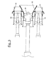
- Each burner 30 is put in connection with at least a first manifold 32 and at least a second fuel adduction manifold 34 and is equipped with at least one pilot injector 36 ( figure 3 ) and one or more main injectors 38 ( figure 3 ) for the adduction of the gaseous fuel inside the burner 30.
- the pilot injector 36 situated in correspondence with the first adduction manifold 32, consists of a combustion nozzle capable of functioning in diffusive flame mode and is therefore activated in the ignition phase of the turbine.
- the main injectors 38 generally arranged around the pilot injector 32 in correspondence with the second adduction manifold 34, are capable of preparing the air/fuel mixture to allow the normal functioning of the turbine, in premixed flame mode.
- At least part of the main injectors 38 and relative fuel adduction manifolds 34 of each burner 30 of the turbine are ventilated or purged only when not in use, i.e. when the turbine is in diffusive flame functioning mode, with a flow, preferably constant, of the same fuel gas or possibly a mixture consisting of fuel gas and a controlled quantity of air, instead of with an air flow.
- a flow preferably constant, of the same fuel gas or possibly a mixture consisting of fuel gas and a controlled quantity of air
- the pressure of the gaseous fuel, when used in the purging phase of each burner 30, must be regulated so as to be greater than the pressure measured inside the combustor 14, in order to prevent the counterflow of the same gas through the injectors 38 and to prevent the formation of condensate inside the feeding duct 16 of the fuel during the purging phase.
- pilot injector 36 and relative fuel adduction manifold 32 can also be involved in the purging phase by means of a preferably constant flow of fuel gas or air/fuel gas mixture when they are not in use, i.e. when the turbine is operating in premixed flame mode (normal functioning). In this way, it is possible to completely eliminate the purging system with compressed air from all the burners 30 of the combustor 14, with a consequent reduction in the number of valves, ducts and control instruments to be applied to the turbine.
- the method for the purging of the combustor in a gas turbine according to the exemplary embodiments can in any case undergo numerous modifications and variants, all included in the same inventive concept.
Landscapes
- Engineering & Computer Science (AREA)
- Chemical & Material Sciences (AREA)
- Combustion & Propulsion (AREA)
- Mechanical Engineering (AREA)
- General Engineering & Computer Science (AREA)
- Processes For Solid Components From Exhaust (AREA)
- Feeding And Controlling Fuel (AREA)
Applications Claiming Priority (1)
| Application Number | Priority Date | Filing Date | Title |
|---|---|---|---|
| IT002404A ITMI20072404A1 (it) | 2007-12-20 | 2007-12-20 | Metodo per lo spurgo controllato del sistema di alimentazione del combustibile nel combustore di una turbina a gas |
Publications (1)
| Publication Number | Publication Date |
|---|---|
| EP2072781A2 true EP2072781A2 (fr) | 2009-06-24 |
Family
ID=40315634
Family Applications (1)
| Application Number | Title | Priority Date | Filing Date |
|---|---|---|---|
| EP08171422A Withdrawn EP2072781A2 (fr) | 2007-12-20 | 2008-12-12 | Procédé de purge commandé du système d'alimentation en carburant dans la chambre de combustion d'un moteur à turbine à gaz |
Country Status (7)
| Country | Link |
|---|---|
| US (1) | US20090158747A1 (fr) |
| EP (1) | EP2072781A2 (fr) |
| JP (1) | JP5449759B2 (fr) |
| KR (1) | KR20090067122A (fr) |
| CN (1) | CN101532433A (fr) |
| CA (1) | CA2647262A1 (fr) |
| IT (1) | ITMI20072404A1 (fr) |
Families Citing this family (4)
| Publication number | Priority date | Publication date | Assignee | Title |
|---|---|---|---|---|
| US20110167782A1 (en) * | 2010-01-13 | 2011-07-14 | Scott Arthur Tetzlaff | Systems and apparatus for a fuel control assembly for use in a gas turbine engine |
| US10378447B2 (en) * | 2016-09-30 | 2019-08-13 | General Electric Company | System and method for purging fuel or coolant from turbomachine |
| CN112944395B (zh) * | 2021-05-12 | 2021-09-07 | 成都中科翼能科技有限公司 | 一种用于燃气轮机的组合式预混器 |
| CN114294680B (zh) * | 2021-12-29 | 2023-07-04 | 哈尔滨工业大学 | 一种中心分级燃气轮机微预混燃烧室 |
Family Cites Families (6)
| Publication number | Priority date | Publication date | Assignee | Title |
|---|---|---|---|---|
| US5329760A (en) * | 1991-10-07 | 1994-07-19 | Fuel Systems Textron, Inc. | Self-sustaining fuel purging fuel injection system |
| US5735117A (en) * | 1995-08-18 | 1998-04-07 | Fuel Systems Textron, Inc. | Staged fuel injection system with shuttle valve and fuel injector therefor |
| JP2877098B2 (ja) * | 1995-12-28 | 1999-03-31 | 株式会社日立製作所 | ガスタービン,コンバインドサイクルプラント及び圧縮機 |
| US6892544B2 (en) * | 2002-04-29 | 2005-05-17 | Honeywell International Inc. | Flow divider & purge air system for a gas turbine engine |
| US6959535B2 (en) * | 2003-01-31 | 2005-11-01 | General Electric Company | Differential pressure induced purging fuel injectors |
| US7677025B2 (en) * | 2005-02-01 | 2010-03-16 | Power Systems Mfg., Llc | Self-purging pilot fuel injection system |
-
2007
- 2007-12-20 IT IT002404A patent/ITMI20072404A1/it unknown
-
2008
- 2008-12-12 EP EP08171422A patent/EP2072781A2/fr not_active Withdrawn
- 2008-12-16 US US12/336,095 patent/US20090158747A1/en not_active Abandoned
- 2008-12-17 JP JP2008320357A patent/JP5449759B2/ja not_active Expired - Fee Related
- 2008-12-18 CA CA002647262A patent/CA2647262A1/fr not_active Abandoned
- 2008-12-22 KR KR1020080131160A patent/KR20090067122A/ko not_active Abandoned
- 2008-12-22 CN CNA2008101889633A patent/CN101532433A/zh active Pending
Also Published As
| Publication number | Publication date |
|---|---|
| JP2009150389A (ja) | 2009-07-09 |
| KR20090067122A (ko) | 2009-06-24 |
| JP5449759B2 (ja) | 2014-03-19 |
| CN101532433A (zh) | 2009-09-16 |
| ITMI20072404A1 (it) | 2009-06-21 |
| CA2647262A1 (fr) | 2009-06-20 |
| US20090158747A1 (en) | 2009-06-25 |
Similar Documents
| Publication | Publication Date | Title |
|---|---|---|
| US7513100B2 (en) | Systems for low emission gas turbine energy generation | |
| EP3076085B1 (fr) | Micromélangeur pour un système de turbine et son procédé associé | |
| CN111140375B (zh) | 用于衰减燃气涡轮发动机中的燃烧动力学的燃烧系统和方法 | |
| US11578871B1 (en) | Gas turbine engine combustor with primary and secondary fuel injectors | |
| EP1493970B1 (fr) | Procédés et appareil pour l'exploitation des chambres de combustion de turbines à gaz | |
| EP3933268B1 (fr) | Ensemble pour une turbomachine comprenant une chambre de combustion, un carter externe et un plénum haute presssion | |
| EP2733424A2 (fr) | Système d'alimentation en carburant servant à fournir du carburant à une section de combustion d'une turbine à gaz | |
| EP4411236A1 (fr) | Système de carburant avec injecteurs disposés radialement pour moteur à turbine à gaz à hydrogène | |
| EP3418638B1 (fr) | Chambre à combustion avec échangeur de chaleur | |
| US12486982B2 (en) | Combustor having a main chamber and one or more trapped vortex cavities | |
| EP2072781A2 (fr) | Procédé de purge commandé du système d'alimentation en carburant dans la chambre de combustion d'un moteur à turbine à gaz | |
| US11885498B2 (en) | Turbine engine with fuel system including a catalytic reformer | |
| EP4411241A1 (fr) | Système de carburant avec injecteurs pilotes et injecteurs principaux pour moteur à turbine à gaz à hydrogène | |
| EP4411232A1 (fr) | Distributeur de carburant à cisaillement élevé | |
| WO2025049170A1 (fr) | Brûleur d'ammoniac | |
| JP2014202475A (ja) | 触媒燃焼空気加熱システム | |
| EP4134589A1 (fr) | Brûleur pilote pour chambre de combustion | |
| EP4660530A1 (fr) | Moteur à turbine comprenant une section d'alimentation en carburant et une section de combustion | |
| US20260063298A1 (en) | Co-firing combustor with gas fuel and liquid ammonia | |
| CN102312727A (zh) | 用于涡轮发动机的添加剂喷射系统及其组装方法 | |
| CN121720116A (zh) | 一种双管组合辅助动力燃烧室、航空器及使用方法 |
Legal Events
| Date | Code | Title | Description |
|---|---|---|---|
| PUAI | Public reference made under article 153(3) epc to a published international application that has entered the european phase |
Free format text: ORIGINAL CODE: 0009012 |
|
| AK | Designated contracting states |
Kind code of ref document: A2 Designated state(s): AT BE BG CH CY CZ DE DK EE ES FI FR GB GR HR HU IE IS IT LI LT LU LV MC MT NL NO PL PT RO SE SI SK TR |
|
| AX | Request for extension of the european patent |
Extension state: AL BA MK RS |
|
| STAA | Information on the status of an ep patent application or granted ep patent |
Free format text: STATUS: THE APPLICATION IS DEEMED TO BE WITHDRAWN |
|
| 18D | Application deemed to be withdrawn |
Effective date: 20160701 |