EP4411236A1 - Système de carburant avec injecteurs disposés radialement pour moteur à turbine à gaz à hydrogène - Google Patents
Système de carburant avec injecteurs disposés radialement pour moteur à turbine à gaz à hydrogène Download PDFInfo
- Publication number
- EP4411236A1 EP4411236A1 EP24154259.6A EP24154259A EP4411236A1 EP 4411236 A1 EP4411236 A1 EP 4411236A1 EP 24154259 A EP24154259 A EP 24154259A EP 4411236 A1 EP4411236 A1 EP 4411236A1
- Authority
- EP
- European Patent Office
- Prior art keywords
- injectors
- groups
- hydrogen
- combustion chamber
- turbine engine
- Prior art date
- Legal status (The legal status is an assumption and is not a legal conclusion. Google has not performed a legal analysis and makes no representation as to the accuracy of the status listed.)
- Pending
Links
Images

Classifications
-
- F—MECHANICAL ENGINEERING; LIGHTING; HEATING; WEAPONS; BLASTING
- F23—COMBUSTION APPARATUS; COMBUSTION PROCESSES
- F23R—GENERATING COMBUSTION PRODUCTS OF HIGH PRESSURE OR HIGH VELOCITY, e.g. GAS-TURBINE COMBUSTION CHAMBERS
- F23R3/00—Continuous combustion chambers using liquid or gaseous fuel
- F23R3/28—Continuous combustion chambers using liquid or gaseous fuel characterised by the fuel supply
- F23R3/286—Continuous combustion chambers using liquid or gaseous fuel characterised by the fuel supply having fuel-air premixing devices
-
- A—HUMAN NECESSITIES
- A61—MEDICAL OR VETERINARY SCIENCE; HYGIENE
- A61P—SPECIFIC THERAPEUTIC ACTIVITY OF CHEMICAL COMPOUNDS OR MEDICINAL PREPARATIONS
- A61P31/00—Antiinfectives, i.e. antibiotics, antiseptics, chemotherapeutics
- A61P31/12—Antivirals
- A61P31/14—Antivirals for RNA viruses
-
- C—CHEMISTRY; METALLURGY
- C12—BIOCHEMISTRY; BEER; SPIRITS; WINE; VINEGAR; MICROBIOLOGY; ENZYMOLOGY; MUTATION OR GENETIC ENGINEERING
- C12N—MICROORGANISMS OR ENZYMES; COMPOSITIONS THEREOF; PROPAGATING, PRESERVING, OR MAINTAINING MICROORGANISMS; MUTATION OR GENETIC ENGINEERING; CULTURE MEDIA
- C12N15/00—Mutation or genetic engineering; DNA or RNA concerning genetic engineering, vectors, e.g. plasmids, or their isolation, preparation or purification; Use of hosts therefor
- C12N15/09—Recombinant DNA-technology
- C12N15/11—DNA or RNA fragments; Modified forms thereof; Non-coding nucleic acids having a biological activity
- C12N15/113—Non-coding nucleic acids modulating the expression of genes, e.g. antisense oligonucleotides; Antisense DNA or RNA; Triplex- forming oligonucleotides; Catalytic nucleic acids, e.g. ribozymes; Nucleic acids used in co-suppression or gene silencing
- C12N15/1131—Non-coding nucleic acids modulating the expression of genes, e.g. antisense oligonucleotides; Antisense DNA or RNA; Triplex- forming oligonucleotides; Catalytic nucleic acids, e.g. ribozymes; Nucleic acids used in co-suppression or gene silencing against viruses
-
- F—MECHANICAL ENGINEERING; LIGHTING; HEATING; WEAPONS; BLASTING
- F23—COMBUSTION APPARATUS; COMBUSTION PROCESSES
- F23R—GENERATING COMBUSTION PRODUCTS OF HIGH PRESSURE OR HIGH VELOCITY, e.g. GAS-TURBINE COMBUSTION CHAMBERS
- F23R3/00—Continuous combustion chambers using liquid or gaseous fuel
- F23R3/002—Wall structures
-
- F—MECHANICAL ENGINEERING; LIGHTING; HEATING; WEAPONS; BLASTING
- F23—COMBUSTION APPARATUS; COMBUSTION PROCESSES
- F23R—GENERATING COMBUSTION PRODUCTS OF HIGH PRESSURE OR HIGH VELOCITY, e.g. GAS-TURBINE COMBUSTION CHAMBERS
- F23R3/00—Continuous combustion chambers using liquid or gaseous fuel
- F23R3/28—Continuous combustion chambers using liquid or gaseous fuel characterised by the fuel supply
- F23R3/283—Attaching or cooling of fuel injecting means including supports for fuel injectors, stems, or lances
-
- F—MECHANICAL ENGINEERING; LIGHTING; HEATING; WEAPONS; BLASTING
- F23—COMBUSTION APPARATUS; COMBUSTION PROCESSES
- F23R—GENERATING COMBUSTION PRODUCTS OF HIGH PRESSURE OR HIGH VELOCITY, e.g. GAS-TURBINE COMBUSTION CHAMBERS
- F23R3/00—Continuous combustion chambers using liquid or gaseous fuel
- F23R3/42—Continuous combustion chambers using liquid or gaseous fuel characterised by the arrangement or form of the flame tubes or combustion chambers
- F23R3/50—Combustion chambers comprising an annular flame tube within an annular casing
-
- C—CHEMISTRY; METALLURGY
- C12—BIOCHEMISTRY; BEER; SPIRITS; WINE; VINEGAR; MICROBIOLOGY; ENZYMOLOGY; MUTATION OR GENETIC ENGINEERING
- C12N—MICROORGANISMS OR ENZYMES; COMPOSITIONS THEREOF; PROPAGATING, PRESERVING, OR MAINTAINING MICROORGANISMS; MUTATION OR GENETIC ENGINEERING; CULTURE MEDIA
- C12N2310/00—Structure or type of the nucleic acid
- C12N2310/10—Type of nucleic acid
- C12N2310/14—Type of nucleic acid interfering nucleic acids [NA]
-
- C—CHEMISTRY; METALLURGY
- C12—BIOCHEMISTRY; BEER; SPIRITS; WINE; VINEGAR; MICROBIOLOGY; ENZYMOLOGY; MUTATION OR GENETIC ENGINEERING
- C12N—MICROORGANISMS OR ENZYMES; COMPOSITIONS THEREOF; PROPAGATING, PRESERVING, OR MAINTAINING MICROORGANISMS; MUTATION OR GENETIC ENGINEERING; CULTURE MEDIA
- C12N2310/00—Structure or type of the nucleic acid
- C12N2310/30—Chemical structure
- C12N2310/32—Chemical structure of the sugar
- C12N2310/321—2'-O-R Modification
-
- C—CHEMISTRY; METALLURGY
- C12—BIOCHEMISTRY; BEER; SPIRITS; WINE; VINEGAR; MICROBIOLOGY; ENZYMOLOGY; MUTATION OR GENETIC ENGINEERING
- C12N—MICROORGANISMS OR ENZYMES; COMPOSITIONS THEREOF; PROPAGATING, PRESERVING, OR MAINTAINING MICROORGANISMS; MUTATION OR GENETIC ENGINEERING; CULTURE MEDIA
- C12N2310/00—Structure or type of the nucleic acid
- C12N2310/30—Chemical structure
- C12N2310/35—Nature of the modification
- C12N2310/351—Conjugate
-
- F—MECHANICAL ENGINEERING; LIGHTING; HEATING; WEAPONS; BLASTING
- F23—COMBUSTION APPARATUS; COMBUSTION PROCESSES
- F23C—METHODS OR APPARATUS FOR COMBUSTION USING FLUID FUEL OR SOLID FUEL SUSPENDED IN A CARRIER GAS OR AIR
- F23C2900/00—Special features of, or arrangements for combustion apparatus using fluid fuels or solid fuels suspended in air; Combustion processes therefor
- F23C2900/9901—Combustion process using hydrogen, hydrogen peroxide water or brown gas as fuel
-
- F—MECHANICAL ENGINEERING; LIGHTING; HEATING; WEAPONS; BLASTING
- F23—COMBUSTION APPARATUS; COMBUSTION PROCESSES
- F23R—GENERATING COMBUSTION PRODUCTS OF HIGH PRESSURE OR HIGH VELOCITY, e.g. GAS-TURBINE COMBUSTION CHAMBERS
- F23R2900/00—Special features of, or arrangements for continuous combustion chambers; Combustion processes therefor
- F23R2900/00002—Gas turbine combustors adapted for fuels having low heating value [LHV]
Definitions
- a gas turbine engine typically includes a fan section, a compressor section, a combustor section and a turbine section. Air entering the compressor section is compressed and delivered into the combustion section where it is mixed with fuel and ignited to generate a high-pressure and temperature exhaust gas flow. The high-pressure and temperature exhaust gas flow expands through the turbine section to drive the compressor and the fan section.
- the compressor section may include low and high pressure compressors, and the turbine section may also include low and high pressure turbines.
- LHF liquid hydrocarbon fuels
- the fuel supply system and liquid injectors are designed for handling and efficient burning of the LHF. For instance, as liquid is much denser than the air (gas) it is to be mixed with, it is necessary for the liquid injectors to atomize the LHF into tiny droplets in order to facilitate more uniform burning. More recently it has been proposed to utilize hydrogen (H 2 ) as a fuel.
- H 2 hydrogen
- a gas turbine engine includes a combustion chamber and groups of injectors for introducing a hydrogen and gas mixture into the combustion chamber.
- Each group of injectors includes radially inner, outer, and intermediate injectors, and each injector includes a hydrogen feed conduit that has an open-cell metallic foam disposed therein.
- the present disclosure may include any one or more of the individual features disclosed above and/or below alone or in any combination thereof.
- like reference numerals designate like elements where appropriate and reference numerals with the addition of one-hundred or multiples thereof designate modified elements that are understood to incorporate the same features and benefits of the corresponding elements.
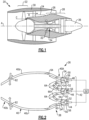
- FIG. 1 schematically illustrates a gas turbine engine 20.
- the example gas turbine engine 20 is a turbofan that generally incorporates a fan section 22, a compressor section 24, a combustor section 26, and a turbine section 28.
- the fan section 22 drives air along a bypass flow path B in a bypass duct defined within a nacelle 30.
- the turbine engine 20 intakes air along a core flow path C into the compressor section 24 for compression and communication into the combustor section 26.
- the compressed air or other combustion gas is mixed with fuel from a fuel system 32 and ignited by igniter 34 to generate an exhaust gas flow that expands through the turbine section 28 and is exhausted through exhaust nozzle 36.
- turbofan turbine engine in the disclosed non-limiting embodiment, it should be understood that the concepts described herein are not limited to use with turbofans as the teachings may be applied to other types of turbine engines.
- the propulsor may be an enclosed fan, the propulsor may be an open propeller.
- the engine 20 of the present disclosure is designed to use gaseous fuel, such as hydrogen, in the fuel system 32.
- the fuel system 32 may carry liquid cryogenic hydrogen or gaseous hydrogen, both of which are provided to the combustor section 26 as gaseous hydrogen.
- a challenge to using hydrogen is that because it is a gas, its handling and combustion properties differ from that of LHF. For instance, hydrogen does not require atomization like a liquid, and hydrogen has higher flammability and different flame characteristics than LHF. Accordingly, injector nozzles and combustors that are designed for hydrogen are needed.
- the engine 20 includes a combustion system 38 that is configured for introducing the hydrogen fuel into the combustor section 26.
- FIG 2 shows a sectioned view of the combustion system 38 taken along a radial plane that includes the engine axis A.
- the combustion system 38 includes an annular combustion chamber 40 in the combustor section 26 for introducing hydrogen and combustion gas (e.g., air in the examples herein).
- the combustion chamber 40 is annularly disposed about the engine axis A and has first and second axial ends 40a/40b and radially inner and outer walls 40c/40d. Radially “inner” and “outer” as used herein indicate radial proximity to the engine axis A.
- Each group 42 has three radially-arranged injectors, which include radially inner, intermediate, and outer injectors 44/46/48.
- Each injector 44/46/48 includes an injector body 50 that defines one or more hydrogen feed conduits 52 and one or more air feed conduits 54.
- the size (at the conduit exits) of all of the hydrogen feed conduits 52 are equivalent, and the size (at the conduit exit) of all of the air feed conduits 54 are equivalent, although the sizes may differ between the hydrogen feed conduits 52 and the air feed conduits 54.
- Each of the hydrogen feed conduits 52 includes an open-cell metallic foam 56 disposed therein.
- the foam 56 serves as a flame arrestor, allowing feed flow of hydrogen but facilitating the prevention of flame propagation back through the injector 44/46/48
- the open-cell metallic foam 56 is formed of an alloy that has low susceptibility to hydrogen embrittlement, such as but not limited to, stainless steel or nickel alloy, and which is corrosion resistant and temperature resistant at the expected operating conditions.
- a "conduit” as used herein is defined by one or more structures that together convey a fluid from one point to another.
- a conduit conveying fluid from point A to point B may include one of, or a combination of: a tube, an aperture defined through a part of an engine, a filter, a pump, and so on, depending on the application and context as would be understood by a person of ordinary skill in the art reading the present disclosure.
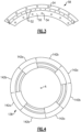
- Each of the injectors 44/46/48 is an annular injector 58, a representative example arc section of which is shown in axial view in Figure 3 .
- the injector body 50 is a circular band through which the conduits 52/54 extend.
- the conduits 52/54 may be angled radially and axially to provide a swirling flow into a mixing region 60 ( Figure 2 ) where the air and hydrogen mix prior to injection into the combustion chamber 40.
- the intermediate injector 46 is a pilot injector for introducing a first percentage of the hydrogen and air mixture into the combustion chamber 40
- the radially inner and outer injectors 44/48 are main injectors for introducing a second percentage of the hydrogen and air mixture into the combustion chamber.
- the pilot injector 46 is used for engine starting, flame stability, and power level controls.
- the percentage of the hydrogen and air mixture provided by the pilot injector 46 versus the percentage provided by the main injectors 44/48 may be adjusted based on engine performance.
- the stoichiometric ratios of the hydrogen and air in the mixtures provided by the pilot injector 46 and the main injectors 44/48 may also be adjusted for further control over engine performance.
- an engine controller may control the percentage and ratios in accordance with a control schedule, such as a lookup table.
- a control schedule such as a lookup table.
- the intermediate injector 46 will be flowing the pilot fuel at the center of the combustor.
- the main injectors 44/48 will come on following a transition fuel schedule to supplement power to the engine.
- the stoichiometry in each mixing region 60 immediately downstream of the pilot and main injectors 46/48/44 is optimized for combustion efficiency and minimized for NOx emission.
- the fuel system 32 may include valves, flow meters, and other known flow control devices that are configured to be operated by the controller in response to the control schedule to control flow of hydrogen and air.
- the combustion system 38 may further include a plurality of trimming or dilution jets 62 axially downstream from the injectors 44/46/48 for further controlling and the combustor radial flame temperature exit profile. There can be 10%-20% of the air for the combustor be entering through the jets 62.
- each main injector 44/48 and its injector body 50 can be optimized for flame stability, combustion efficiency, liner durability and minimal NOx emission.
- the outer main injector 48 may be arranged to have a higher fuel-air ratio than the inner main injector 44, hence exhausting with a higher gas temperature at the tip than the root of the turbine blades downstream. Such setting of the fuel-air mixture ratio across the outer, intermediate and inner fuel injectors can be optimized for turbine efficiency and hot section durability.
- the combustion chamber 40 may also include cooling jets 64 for introducing additional air for combustion and cooling the walls of the chamber 40.
- Some of the cooling jets 64 are located in conical fairings 66 located radially between, respectively, the inner and intermediate injectors 44/46 and the outer and intermediate injectors 48/46.
- the fairings 66 bound a radial portion of the mixing region 60 and facilitate downstream flow of the hydrogen and air mixture into the combustion chamber 40.
- the groups 42 of injectors introduce 70% to 80% of the air through the passages 54 for combustion into the combustion chamber 40
- the cooling jets 64 introduce 10% to 20% of the air for combustion into the combustion chamber 40. Such percentages enable a lean burn of the hydrogen, which also facilitates low NOx emissions.
- Figure 4 illustrates another example of a combustion system 138.
- the system 138 includes groups 142a/142b of injectors arranged about the engine axis A.
- each of the groups 142a includes injectors 144a/146a/148a
- each of the groups 142b includes injectors 144b/146b/148b.
- Each group 142a/142b is analogous to the aforementioned group 42 except that the injectors 144a/146a/148a of the group 142a are all pilot injectors for introducing a first percentage of the hydrogen and air mixture into the combustion chamber 40 and the injectors 144b/146b/148b of the group 142b are all main injectors for introducing a second percentage of the hydrogen and air mixture into the combustion chamber 40.
- the groups 142a/142b circumferentially alternate such that each of the pilot groups 142a is circumferentially between two of the main groups 142b and each of the main groups 142b is circumferentially between two of the pilot groups 142a.
- the pilot groups 142a each have first arc length (L1) about the axis A
- the main groups 142b each have a second arc length (L2) about the axis
- the first arc length L1 is different than, such as smaller than, the second arc length L2.
- a turbine engine 20 includes a combustion chamber 40 disposed about an axis A and having first and second axial ends 40a/40b and radially inner and outer walls 40c/40d.
- Groups 42 of injectors 44/46/48 are disposed about the axis A at the first axial end 40a for introducing a hydrogen and gas mixture into the combustion chamber 40.
- Each of the groups 42 includes radially inner, outer, and intermediate injectors 44/46/48.
- Each of the injectors 44/46/48 has a hydrogen feed conduit 52 including an open-cell metallic foam 56 disposed therein.
- the intermediate injector 46 is a pilot injector for introducing a first percentage of the hydrogen and gas mixture into the combustion chamber 40.
- the radially inner and outer injectors 44/48 are main injectors for introducing a second percentage of the hydrogen and gas mixture into the combustion chamber 40.
- the combustion chamber 40 includes first and second conical fairings 66 radially between, respectively, the inner and intermediate injectors 44/46 and the outer and intermediate injectors 48/46.
- the first and second conical fairings 66 include cooling jets 64.
- the groups include pilot groups 142a in which the injectors are pilot injectors 144a/146a/148a for introducing a first percentage of the hydrogen and gas mixture into the combustion chamber 40.
- the groups include main groups 142b in which the injectors are main injectors 144b/146b/148b for introducing a second percentage of the hydrogen and gas mixture into the combustion chamber 40.
- pilot groups and the main groups 142a/142b circumferentially alternate such that each of the pilot groups 142a is circumferentially between two of the main groups 142b and each of the main groups 142b is circumferentially between two of the pilot groups 142a.
- the pilot groups 142a each have first arc length L1 about the axis A
- the main groups 142b each have a second arc length L2 about the axis A
- the first arc length L1 is smaller than the second arc length L2.
Landscapes
- Engineering & Computer Science (AREA)
- Chemical & Material Sciences (AREA)
- Life Sciences & Earth Sciences (AREA)
- Health & Medical Sciences (AREA)
- General Engineering & Computer Science (AREA)
- Combustion & Propulsion (AREA)
- Mechanical Engineering (AREA)
- Genetics & Genomics (AREA)
- Biomedical Technology (AREA)
- Molecular Biology (AREA)
- Organic Chemistry (AREA)
- Virology (AREA)
- Biotechnology (AREA)
- General Health & Medical Sciences (AREA)
- Bioinformatics & Cheminformatics (AREA)
- Wood Science & Technology (AREA)
- Zoology (AREA)
- Biophysics (AREA)
- Pharmacology & Pharmacy (AREA)
- Microbiology (AREA)
- Communicable Diseases (AREA)
- Oncology (AREA)
- Chemical Kinetics & Catalysis (AREA)
- General Chemical & Material Sciences (AREA)
- Medicinal Chemistry (AREA)
- Nuclear Medicine, Radiotherapy & Molecular Imaging (AREA)
- Biochemistry (AREA)
- Animal Behavior & Ethology (AREA)
- Public Health (AREA)
- Veterinary Medicine (AREA)
- Plant Pathology (AREA)
- Physics & Mathematics (AREA)
- Turbine Rotor Nozzle Sealing (AREA)
- Pre-Mixing And Non-Premixing Gas Burner (AREA)
- Pharmaceuticals Containing Other Organic And Inorganic Compounds (AREA)
Applications Claiming Priority (1)
| Application Number | Priority Date | Filing Date | Title |
|---|---|---|---|
| US202363482854P | 2023-02-02 | 2023-02-02 |
Publications (1)
| Publication Number | Publication Date |
|---|---|
| EP4411236A1 true EP4411236A1 (fr) | 2024-08-07 |
Family
ID=89767107
Family Applications (1)
| Application Number | Title | Priority Date | Filing Date |
|---|---|---|---|
| EP24154259.6A Pending EP4411236A1 (fr) | 2023-02-02 | 2024-01-26 | Système de carburant avec injecteurs disposés radialement pour moteur à turbine à gaz à hydrogène |
Country Status (3)
| Country | Link |
|---|---|
| US (2) | US12298008B2 (fr) |
| EP (1) | EP4411236A1 (fr) |
| CA (1) | CA3227895A1 (fr) |
Families Citing this family (4)
| Publication number | Priority date | Publication date | Assignee | Title |
|---|---|---|---|---|
| US20110040016A1 (en) | 2008-04-21 | 2011-02-17 | Yakulis Jr George | Curable compositions that form a high modulus polyurea |
| US20110076485A1 (en) | 2009-09-29 | 2011-03-31 | Ppg Industries Ohio, Inc. | Substrates coated with clear polyurea film-forming compositions |
| US8691929B2 (en) | 2010-11-18 | 2014-04-08 | Ppg Industries Ohio, Inc. | Curable compositions that form a polyurea demonstrating elongation properties over a large temperature range |
| EP4411235B1 (fr) * | 2023-02-02 | 2025-08-27 | Pratt & Whitney Canada Corp. | Moteur à turbine à gaz à hydrogène avec anneau d'injecteur et alimentation étagée de carburant |
Citations (6)
| Publication number | Priority date | Publication date | Assignee | Title |
|---|---|---|---|---|
| US5303542A (en) * | 1992-11-16 | 1994-04-19 | General Electric Company | Fuel supply control method for a gas turbine engine |
| EP0780631A2 (fr) * | 1995-12-19 | 1997-06-25 | DaimlerChrysler Aerospace Airbus Gesellschaft mit beschränkter Haftung | Procédé et brûleur pour la combustion d'hydrogène |
| US6474070B1 (en) * | 1998-06-10 | 2002-11-05 | General Electric Company | Rich double dome combustor |
| US20050188703A1 (en) * | 2004-02-26 | 2005-09-01 | Sprouse Kenneth M. | Non-swirl dry low nox (dln) combustor |
| WO2018144008A1 (fr) * | 2017-02-03 | 2018-08-09 | Siemens Aktiengesellschaft | Chambre de combustion avec pré-mélangeur en treillis tridimensionnel |
| US20220099299A1 (en) * | 2020-09-30 | 2022-03-31 | Rolls-Royce Plc | Fuel injection |
Family Cites Families (9)
| Publication number | Priority date | Publication date | Assignee | Title |
|---|---|---|---|---|
| US5682747A (en) * | 1996-04-10 | 1997-11-04 | General Electric Company | Gas turbine combustor heat shield of casted super alloy |
| US9719419B2 (en) | 2011-03-16 | 2017-08-01 | Mitsubishi Heavy Industries, Ltd. | Gas turbine combustor with top hat nozzle arrangements |
| US20130219897A1 (en) | 2012-02-28 | 2013-08-29 | Mitsubishi Heavy Industries, Ltd. | Combustor and gas turbine |
| EP2930430A1 (fr) * | 2014-04-07 | 2015-10-14 | Siemens Aktiengesellschaft | Bec de brûleur et brûleur d'une turbine à gaz |
| US10508811B2 (en) * | 2016-10-03 | 2019-12-17 | United Technologies Corporation | Circumferential fuel shifting and biasing in an axial staged combustor for a gas turbine engine |
| US10465909B2 (en) * | 2016-11-04 | 2019-11-05 | General Electric Company | Mini mixing fuel nozzle assembly with mixing sleeve |
| US11480337B2 (en) | 2019-11-26 | 2022-10-25 | Collins Engine Nozzles, Inc. | Fuel injection for integral combustor and turbine vane |
| GB2602037A (en) * | 2020-12-16 | 2022-06-22 | Siemens Energy Global Gmbh & Co Kg | Method of operating a combustor for a gas turbine |
| US12601488B2 (en) * | 2021-07-02 | 2026-04-14 | General Electric Company | Premixer array |
-
2024
- 2024-01-26 EP EP24154259.6A patent/EP4411236A1/fr active Pending
- 2024-01-29 US US18/425,080 patent/US12298008B2/en active Active
- 2024-02-01 CA CA3227895A patent/CA3227895A1/fr active Pending
-
2025
- 2025-07-31 US US19/287,091 patent/US20260022379A1/en active Pending
Patent Citations (6)
| Publication number | Priority date | Publication date | Assignee | Title |
|---|---|---|---|---|
| US5303542A (en) * | 1992-11-16 | 1994-04-19 | General Electric Company | Fuel supply control method for a gas turbine engine |
| EP0780631A2 (fr) * | 1995-12-19 | 1997-06-25 | DaimlerChrysler Aerospace Airbus Gesellschaft mit beschränkter Haftung | Procédé et brûleur pour la combustion d'hydrogène |
| US6474070B1 (en) * | 1998-06-10 | 2002-11-05 | General Electric Company | Rich double dome combustor |
| US20050188703A1 (en) * | 2004-02-26 | 2005-09-01 | Sprouse Kenneth M. | Non-swirl dry low nox (dln) combustor |
| WO2018144008A1 (fr) * | 2017-02-03 | 2018-08-09 | Siemens Aktiengesellschaft | Chambre de combustion avec pré-mélangeur en treillis tridimensionnel |
| US20220099299A1 (en) * | 2020-09-30 | 2022-03-31 | Rolls-Royce Plc | Fuel injection |
Also Published As
| Publication number | Publication date |
|---|---|
| CA3227895A1 (fr) | 2025-04-16 |
| US20260022379A1 (en) | 2026-01-22 |
| US12298008B2 (en) | 2025-05-13 |
| US20240263796A1 (en) | 2024-08-08 |
Similar Documents
| Publication | Publication Date | Title |
|---|---|---|
| EP4411236A1 (fr) | Système de carburant avec injecteurs disposés radialement pour moteur à turbine à gaz à hydrogène | |
| US10465909B2 (en) | Mini mixing fuel nozzle assembly with mixing sleeve | |
| EP4174379B1 (fr) | Procédés de fonctionnement d'une chambre de combustion de turbomachine avec de l'hydrogène | |
| JP5400936B2 (ja) | ガスタービンエンジン内で燃料を燃焼させるための方法及び装置 | |
| EP3537048A1 (fr) | Injecteur de carburant pour combustion sous- stochiométrique | |
| US4463568A (en) | Fuel injector for gas turbine engines | |
| EP1830129A2 (fr) | Procédé et appareil d'assemblage de moteurs de turbine à gaz | |
| JP4997018B2 (ja) | 一次燃料噴射器及び複数の二次燃料噴射ポートを有するガスタービンエンジン燃焼器のミキサ組立体のためのパイロットミキサ | |
| EP4411234A1 (fr) | Moteur à turbine à gaz à hydrogène avec anneau d'injecteur | |
| EP4411231A1 (fr) | Injecteur avec générateur de turbulence pour moteur à turbine à gaz à hydrogène | |
| US20220373182A1 (en) | Pilot fuel nozzle assembly with vented venturi | |
| EP4411241A1 (fr) | Système de carburant avec injecteurs pilotes et injecteurs principaux pour moteur à turbine à gaz à hydrogène | |
| EP4411243A1 (fr) | Injecteur avec carénage et passage annulaire pour moteur à turbine à gaz entraîné par hydrogène | |
| EP4411226A1 (fr) | Passage d'air central avec distributeur de carburant radial | |
| EP4411239A1 (fr) | Distributeur de carburant à hydrogène | |
| EP4411232A1 (fr) | Distributeur de carburant à cisaillement élevé | |
| EP4411235B1 (fr) | Moteur à turbine à gaz à hydrogène avec anneau d'injecteur et alimentation étagée de carburant | |
| EP4411240A1 (fr) | Dispositif de tourbillonnement d'air combiné et distributeur de carburant | |
| US12215868B2 (en) | Injector with disc for hydrogen-driven gas turbine engine | |
| CA3223578A1 (fr) | Chambre de combustion comprenant une injection de carburant centrale et un melange d~air en aval |
Legal Events
| Date | Code | Title | Description |
|---|---|---|---|
| PUAI | Public reference made under article 153(3) epc to a published international application that has entered the european phase |
Free format text: ORIGINAL CODE: 0009012 |
|
| STAA | Information on the status of an ep patent application or granted ep patent |
Free format text: STATUS: THE APPLICATION HAS BEEN PUBLISHED |
|
| AK | Designated contracting states |
Kind code of ref document: A1 Designated state(s): AL AT BE BG CH CY CZ DE DK EE ES FI FR GB GR HR HU IE IS IT LI LT LU LV MC ME MK MT NL NO PL PT RO RS SE SI SK SM TR |
|
| STAA | Information on the status of an ep patent application or granted ep patent |
Free format text: STATUS: REQUEST FOR EXAMINATION WAS MADE |
|
| 17P | Request for examination filed |
Effective date: 20250207 |
|
| STAA | Information on the status of an ep patent application or granted ep patent |
Free format text: STATUS: EXAMINATION IS IN PROGRESS |
|
| 17Q | First examination report despatched |
Effective date: 20250328 |
|
| GRAP | Despatch of communication of intention to grant a patent |
Free format text: ORIGINAL CODE: EPIDOSNIGR1 |
|
| STAA | Information on the status of an ep patent application or granted ep patent |
Free format text: STATUS: GRANT OF PATENT IS INTENDED |