EP2072812A2 - Verfahren und Einrichtung zur Handhabung einer Rotornabe einer Windenergieanlage - Google Patents
Verfahren und Einrichtung zur Handhabung einer Rotornabe einer Windenergieanlage Download PDFInfo
- Publication number
- EP2072812A2 EP2072812A2 EP08021598A EP08021598A EP2072812A2 EP 2072812 A2 EP2072812 A2 EP 2072812A2 EP 08021598 A EP08021598 A EP 08021598A EP 08021598 A EP08021598 A EP 08021598A EP 2072812 A2 EP2072812 A2 EP 2072812A2
- Authority
- EP
- European Patent Office
- Prior art keywords
- rotor
- tilting
- lifting
- rotor hub
- hub
- Prior art date
- Legal status (The legal status is an assumption and is not a legal conclusion. Google has not performed a legal analysis and makes no representation as to the accuracy of the status listed.)
- Granted
Links
- 238000000034 method Methods 0.000 title claims abstract description 22
- 230000005484 gravity Effects 0.000 claims description 18
- 238000004904 shortening Methods 0.000 claims description 2
- 230000003247 decreasing effect Effects 0.000 claims 1
- 238000009434 installation Methods 0.000 abstract description 7
- 241000124872 Grus grus Species 0.000 abstract 1
- 238000010276 construction Methods 0.000 description 8
- 239000000725 suspension Substances 0.000 description 6
- 230000004913 activation Effects 0.000 description 5
- 238000002485 combustion reaction Methods 0.000 description 2
- 238000004146 energy storage Methods 0.000 description 2
- 230000002349 favourable effect Effects 0.000 description 2
- 230000003213 activating effect Effects 0.000 description 1
- 238000007667 floating Methods 0.000 description 1
- 238000010248 power generation Methods 0.000 description 1
- 230000002441 reversible effect Effects 0.000 description 1
- XLYOFNOQVPJJNP-UHFFFAOYSA-N water Substances O XLYOFNOQVPJJNP-UHFFFAOYSA-N 0.000 description 1
Images




Classifications
-
- F—MECHANICAL ENGINEERING; LIGHTING; HEATING; WEAPONS; BLASTING
- F03—MACHINES OR ENGINES FOR LIQUIDS; WIND, SPRING, OR WEIGHT MOTORS; PRODUCING MECHANICAL POWER OR A REACTIVE PROPULSIVE THRUST, NOT OTHERWISE PROVIDED FOR
- F03D—WIND MOTORS
- F03D13/00—Assembly, mounting or commissioning of wind motors; Arrangements specially adapted for transporting wind motor components
- F03D13/10—Assembly of wind motors; Arrangements for erecting wind motors
-
- B—PERFORMING OPERATIONS; TRANSPORTING
- B66—HOISTING; LIFTING; HAULING
- B66C—CRANES; LOAD-ENGAGING ELEMENTS OR DEVICES FOR CRANES, CAPSTANS, WINCHES, OR TACKLES
- B66C1/00—Load-engaging elements or devices attached to lifting or lowering gear of cranes or adapted for connection therewith for transmitting lifting forces to articles or groups of articles
- B66C1/10—Load-engaging elements or devices attached to lifting or lowering gear of cranes or adapted for connection therewith for transmitting lifting forces to articles or groups of articles by mechanical means
- B66C1/108—Load-engaging elements or devices attached to lifting or lowering gear of cranes or adapted for connection therewith for transmitting lifting forces to articles or groups of articles by mechanical means for lifting parts of wind turbines
-
- B—PERFORMING OPERATIONS; TRANSPORTING
- B66—HOISTING; LIFTING; HAULING
- B66C—CRANES; LOAD-ENGAGING ELEMENTS OR DEVICES FOR CRANES, CAPSTANS, WINCHES, OR TACKLES
- B66C1/00—Load-engaging elements or devices attached to lifting or lowering gear of cranes or adapted for connection therewith for transmitting lifting forces to articles or groups of articles
- B66C1/10—Load-engaging elements or devices attached to lifting or lowering gear of cranes or adapted for connection therewith for transmitting lifting forces to articles or groups of articles by mechanical means
- B66C1/62—Load-engaging elements or devices attached to lifting or lowering gear of cranes or adapted for connection therewith for transmitting lifting forces to articles or groups of articles by mechanical means comprising article-engaging members of a shape complementary to that of the articles to be handled
-
- F—MECHANICAL ENGINEERING; LIGHTING; HEATING; WEAPONS; BLASTING
- F03—MACHINES OR ENGINES FOR LIQUIDS; WIND, SPRING, OR WEIGHT MOTORS; PRODUCING MECHANICAL POWER OR A REACTIVE PROPULSIVE THRUST, NOT OTHERWISE PROVIDED FOR
- F03D—WIND MOTORS
- F03D1/00—Wind motors with rotation axis substantially parallel to the air flow entering the rotor
- F03D1/06—Rotors
- F03D1/065—Rotors characterised by their construction elements
- F03D1/0658—Arrangements for fixing wind-engaging parts to a hub
-
- F—MECHANICAL ENGINEERING; LIGHTING; HEATING; WEAPONS; BLASTING
- F05—INDEXING SCHEMES RELATING TO ENGINES OR PUMPS IN VARIOUS SUBCLASSES OF CLASSES F01-F04
- F05B—INDEXING SCHEME RELATING TO WIND, SPRING, WEIGHT, INERTIA OR LIKE MOTORS, TO MACHINES OR ENGINES FOR LIQUIDS COVERED BY SUBCLASSES F03B, F03D AND F03G
- F05B2230/00—Manufacture
- F05B2230/60—Assembly methods
- F05B2230/61—Assembly methods using auxiliary equipment for lifting or holding
-
- Y—GENERAL TAGGING OF NEW TECHNOLOGICAL DEVELOPMENTS; GENERAL TAGGING OF CROSS-SECTIONAL TECHNOLOGIES SPANNING OVER SEVERAL SECTIONS OF THE IPC; TECHNICAL SUBJECTS COVERED BY FORMER USPC CROSS-REFERENCE ART COLLECTIONS [XRACs] AND DIGESTS
- Y02—TECHNOLOGIES OR APPLICATIONS FOR MITIGATION OR ADAPTATION AGAINST CLIMATE CHANGE
- Y02E—REDUCTION OF GREENHOUSE GAS [GHG] EMISSIONS, RELATED TO ENERGY GENERATION, TRANSMISSION OR DISTRIBUTION
- Y02E10/00—Energy generation through renewable energy sources
- Y02E10/70—Wind energy
- Y02E10/72—Wind turbines with rotation axis in wind direction
-
- Y—GENERAL TAGGING OF NEW TECHNOLOGICAL DEVELOPMENTS; GENERAL TAGGING OF CROSS-SECTIONAL TECHNOLOGIES SPANNING OVER SEVERAL SECTIONS OF THE IPC; TECHNICAL SUBJECTS COVERED BY FORMER USPC CROSS-REFERENCE ART COLLECTIONS [XRACs] AND DIGESTS
- Y02—TECHNOLOGIES OR APPLICATIONS FOR MITIGATION OR ADAPTATION AGAINST CLIMATE CHANGE
- Y02E—REDUCTION OF GREENHOUSE GAS [GHG] EMISSIONS, RELATED TO ENERGY GENERATION, TRANSMISSION OR DISTRIBUTION
- Y02E10/00—Energy generation through renewable energy sources
- Y02E10/70—Wind energy
- Y02E10/728—Onshore wind turbines
-
- Y—GENERAL TAGGING OF NEW TECHNOLOGICAL DEVELOPMENTS; GENERAL TAGGING OF CROSS-SECTIONAL TECHNOLOGIES SPANNING OVER SEVERAL SECTIONS OF THE IPC; TECHNICAL SUBJECTS COVERED BY FORMER USPC CROSS-REFERENCE ART COLLECTIONS [XRACs] AND DIGESTS
- Y02—TECHNOLOGIES OR APPLICATIONS FOR MITIGATION OR ADAPTATION AGAINST CLIMATE CHANGE
- Y02P—CLIMATE CHANGE MITIGATION TECHNOLOGIES IN THE PRODUCTION OR PROCESSING OF GOODS
- Y02P70/00—Climate change mitigation technologies in the production process for final industrial or consumer products
- Y02P70/50—Manufacturing or production processes characterised by the final manufactured product
Definitions
- the invention relates to a method for handling a rotor hub of a wind turbine or for handling a rotor of a wind turbine by means of a lifting device, in particular when building a wind turbine or during assembly or disassembly of a rotor of a wind turbine to a wind turbine.
- the invention further relates to a device for handling a rotor hub of a wind energy plant or for handling a rotor of a wind energy plant, in particular when constructing a wind turbine or during assembly or disassembly of a rotor of a wind turbine to a wind turbine.
- the invention relates to a use of a tilting device for the erection or disassembly of a wind energy plant.
- the object of the present invention is the assembly and the erection and To easily improve the disassembly of a wind turbine, the design effort for this should be kept as low as possible. In particular, the effort to remove lifting means should be reduced.
- This object is achieved by a method for handling a rotor hub of a wind turbine or for handling a rotor of a wind turbine by means of a lifting device, in particular when building a wind turbine or during assembly or disassembly of a rotor of a wind turbine to a wind turbine, in particular a rotor hub or a rotor is arranged with a mounting side of a tower of a wind turbine or is, wherein the rotor hub or the rotor is raised or held by the lifting device, the rotor hub is tilted in the raised state by means of a rotor hub engaging on the tilting means from the original raised position by a predetermined tilt angle or the rotor is tilted from the original raised position by a predetermined tilting angle by means of a tilting device acting on the rotor blade roots of the rotor blades of the rotor.
- the method is carried out when erecting a wind turbine, wherein a rotor hub or a rotor is arranged with a mounting side of a tower of a wind turbine, the rotor hub or the rotor is lifted with a lifting device, in particular crane, after lifting the rotor hub or after the lifting of the rotor in the raised state is tilted by a predetermined tilt angle by means of a tilting device acting on the rotor hub or on the rotor from the original raised position.
- a lifting device in particular crane
- the invention is based on the idea that, for example, using only one crane as the only lifting device to be mounted on a tower or on a nacelle of the tower rotor hub or a corresponding rotor are lifted with rotor hub and after lifting the rotor or the rotor hub the rotor hub or the rotor is rotated in the suspended state by a predetermined tilting axis and in particular with a predetermined tilt angle by the activation of a tilting device provided between the boom and the rotor hub.
- the tilting of the rotor hub or of the rotor is carried out with the omission of a second (auxiliary) crane.
- a horizontally oriented rotor By running through the tilting tilting example, a horizontally oriented rotor, the entire rotor is brought in the raised state by actuation or using the tilting device in a tilted position for horizontal alignment.
- guide cables or the like are provided in one embodiment, wherein these guide cables or devices cause no tilting of the rotor. This is done by the tilting device.
- the tilting device is connected to the rotor hub and the lifting device, in particular the jib or the hoisting cable extending on the jib, during the alignment of the rotor hub arranged on the lifting device or on an abutment point.
- controllable tilting device also allows a positionally accurate control of the tilting position of the rotor hub or of the rotor hanging in the lifting device state.
- the tilting device according to the invention it is possible by the tilting device according to the invention, the inclination to set a rotor or a rotor hub in relation to, for example, a rotor shaft plane and align a rotor accordingly. This is done in particular in a remote-controlled manner, so that in the raised (horizontal) starting position of a rotor is tilted by activation or actuation of the tilting means by a predetermined tilt angle.
- the tilting device it is also possible, for example, in the construction of offshore wind turbines to complete a rotor on land by arranging rotor blades on a rotor hub and the finished rotor by means of a float, such as a jack-up barge to transport to the erection site of the wind turbine.
- a float such as a jack-up barge
- the legs of the jack-up barge are extended, so that the floating body above the water is brought stationary in a stable working position.
- a position-controlled or angularly controlled tilting movement of the rotor hub or the rotor is a precise control or control, so that during assembly of the inclination angle of the rotor can be changed in a simple manner.
- a further lifting means for example an auxiliary crane or the like, saved.
- the tilting operations are reversible, so that the process steps of the tilting process essential to the invention during assembly of a wind energy installation can be reversed when a rotor is attached to a nacelle or a rotor shaft during disassembly of the installation, so that during a dismantling process an installed system, the rotor after removal from the nacelle or the rotor shaft by means of the lifting device is held and can be brought by means of the tilting device from the erected position in a horizontal position by tilting the rotor on the lifting device or on the crane.
- the assembly of a wind turbine is described below, it is understood in the context of the invention and the disclosure that the reversibly executable steps for dismantling a system in appropriate width are read.
- the tilting operation of a rotor or of the rotor hub is initiated when the tilting device designed as an activating means is activated or switched on the lifting means of the lifting device to initiate the tilting operation.
- the tilting means may comprise a hydraulic or a drive or the like, which is actuated to perform the tilting.
- the rotor hub is tilted with at least one rotor blade arranged thereon by means of the tilting device.
- the rotor blade or the rotor blades are connected to the rotor hub via corresponding flange, wherein the assembly of the rotor rotor hub and rotor blades takes place on a flat surface, so that the finished rotor is arranged after assembly in a horizontal position.
- the tilting device according to the invention which is applied to the rotor hub in one embodiment, designed such that even rotors with a weight of over 80 t, in particular over 100 t, are tilted in the raised state.
- the rotor hub or the rotor hub with at least one rotor blade (rotor) arranged thereon are tilted into a mounting position.
- the rotor hub or the rotor with the lifting device can thus For example, a crane to the tower or the nacelle to which the rotor hub is to be attached, are approximated to perform a final assembly of the rotor or the rotor hub there.
- the rotor or the rotor hub is tilted with at least one rotor blade arranged thereon by means of the tilting device.
- the rotor or the rotor hub with at least one rotor blade arranged therein is furthermore attached to the tower or to a nacelle of the tower.
- the rotor hub or the rotor is dismantled or removed from the tower or from the nacelle and then tilted by means of the tilting device.
- the tilting device prior to raising the rotor hub, the tilting device is connected to the rotor hub or before the lifting of the rotor, the tilting device is connected to the rotor.
- the rotor hub or the rotor is advantageously in an assembly-ready state, so that the tilting device is attached to the rotor hub in order to carry out the assembly.
- the tilting device is preferably arranged between a lifting device of the lifting device and the rotor hub, or the tilting device is arranged between a lifting device of the lifting device and the rotor.
- the tilting means on an abutment point on which the lifting means or the lifting device is struck.
- the tilting operation preferably takes place by means of the tilting device suspended freely in space on a hoist rope of the lifting device, wherein the rotor is optionally stabilized by auxiliary cables against incident wind gusts.
- the mounting method is characterized in that the rotor hub or the rotor is or is raised using or using a crane as a lifting device.
- the crane is set up or placed next to the wind energy plant to be erected, wherein furthermore advantageously the crane is not connected to the wind energy plant as an independent unit or is arranged thereon.
- the crane After mounting the rotor on the nacelle of the tube tower, the crane is transported or moved after its use by the installation site to another installation site.
- the object is achieved by a device for handling a rotor hub of a wind turbine or for handling a rotor of a wind turbine, in particular when constructing a wind turbine or during assembly or disassembly of a rotor of a wind turbine to a wind turbine, wherein the device is designed as a tilting device which Tilting device has fastening means with which the tilting device is fastened to the rotor hub and / or to the rotor blade roots of the rotor blades of the rotor arranged on the rotor hub, the tilting device having an attachment point for a lifting device, in particular a lifting device, wherein in the raised state the rotor hub on the lifting device during tilting Rotor hub by means of the tilting means arranged on the tilting means, the position of the rotor hub is changed or in the raised state of the rotor on the lifting means when tilting the rotor by means of the tilting means arranged on the lifting means, the position of the rotor hub is changed
- a lifting means of a lifting device e.g. a boom or a hoisting rope of a crane, arranged at an abutment point of the tilting means, wherein the tilting means is provided with fastening means, so that the tilting means is attached to a rotor hub or a rotor or is, and the tilting means is formed such that on the tilting means arranged rotor hub or the rotor arranged thereon is brought in the raised state from the original raised position in a tilted position with a predetermined tilt angle by actuation or activation of the tilting means.
- a lifting device has a jib and / or a hoisting cable extending over a jib or a hoisting means, preferably arranged on a jib, to which the tilting device according to the invention is attached to an abutment point.
- a force application point for the lifting means arranged thereon.
- the tilting means is struck by means of a releasable connection to the stop point.
- a lifting device which is equipped with a tilting device according to the invention or is connected, in addition to a crane, a rope or a lifting platform, for example in the form of a jack-up barge or the like.
- the distance of, in particular during tilting fixed stop point to the center of gravity of the rotor hub when tilting the rotor hub or the distance of the attachment point to the center of gravity of the rotor during tilting of the rotor or during the tilting substantially remains constant.
- the rotor hub or the rotor is tilted in the (respective) center of gravity, wherein the preferred tilting axis is formed during tilting of the rotor hub or the rotor substantially horizontally.
- the distance of the, in particular tilting fixed, stop point to the center of gravity of the rotor hub when tilting the rotor hub or the distance of the attachment point to the center of gravity of the rotor during tilting of the rotor or during the tilting process depending on the design of the tilting device especially enlarged or reduced.
- the, in particular horizontally extending, tilting axis about which the tilting process of the rotor or the rotor hub is carried out lie outside the center of gravity of the rotor hub or the rotor, wherein the tilting axis can change its position in dependence on the tilted position of the rotor hub or the rotor, ie wanders, in particular, the preferred horizontal orientation of the tilt axis remains unchanged.
- the fastening means of the tilting device is designed as a frame, in particular mounting frame, or as a frame or as a mounting bracket or as an adapter.
- the rotor or the rotor hub is releasably connected to the tilting device well, to subsequently perform a tilt.
- the tilting device can also have a lifting arm and / or a lever arm, wherein for the tilting of the rotor or rotor hub the lifting arm or the lever arm are movably or movably arranged on the rotor hub or on a fastening element or means of the tilting device provided on the rotor hub or become.
- the tilting device has a drive and / or an actuator.
- the actuator as a lifting cylinder, in particular telescopic cylinder, or as a winch or as a cable, in particular with rope shortening / rope extension, or as a rotary drive, in particular with a drive pinion formed.
- the drive is engaged with the guide rail in order to initiate the tilting of the rotor hub or of the rotor by means of the tilting device by actuation of the drive or of the motor or to influence or control the tilting operation specifically from the outside.
- the guide rail in which a drive (smotor) engages, is formed with a toothed rim or with a bolt rim or a roller chain.
- a simple design and handling of the tilting device results from the fact that the drive is arranged on the lifting means of the lifting device or attachment point or on the guide rail or is.
- the object of the invention is achieved by a use of a tilting device for the erection or disassembly of a wind power plant, wherein the tilting device is designed as described above, in particular using a lifting device.
- a tilting device during or for erection or disassembly of a wind energy plant, it is possible that a rotor hub or a rotor is lifted or is by means of a lifting device, and in particular the rotor hub or the rotor is arranged on a tower of a wind turbine or is, wherein the Tilting means between the lifting means, for example, on a boom of the lifting device or a hoist rope of the lifting device and the rotor hub or the rotor is arranged, so that the rotor hub or the rotor by means of the tilting means by a predetermined tilt angle from the original raised Position is tilted by or after actuation or activation of the tilting device is or is.
- the tilting device is used temporarily for mounting or dismounting components of a wind energy plant, wherein in particular the components, e.g. Rotors or rotor hubs are brought into an assembly ready position after the components are in the raised position and are brought by operating the tilting device in a tilted position, wherein it is no longer necessary according to the invention to use other lifting means to a rotor or a bring corresponding component in an assembly ready position with a predetermined angle of inclination or tilt angle.
- the components e.g. Rotors or rotor hubs are brought into an assembly ready position after the components are in the raised position and are brought by operating the tilting device in a tilted position, wherein it is no longer necessary according to the invention to use other lifting means to a rotor or a bring corresponding component in an assembly ready position with a predetermined angle of inclination or tilt angle.
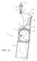
- Fig. 1 a shows schematically in a side view a rotor 10 of a wind turbine in the raised state, wherein the rotor 10, with a rotor hub 11, which is shown schematically in cross-section, and a rotor hub 11 arranged on the rotor blade 12 is formed.
- a plurality of, preferably three, rotor blades 12 are uniformly arranged on the rotor hub 11 and connected to the rotor hub 11 with flange connections.
- the drawing of other rotor blades was omitted.
- the rotor 10 was mounted in the horizontal state on a free flat surface. This can be done, for example, at the construction site of a wind turbine. If the wind turbines are erected offshore, it is for example possible that the rotors 10 are manufactured on land in the horizontal state and then transported by means of a float to the construction site. At the erection site itself, the rotors 10 are raised from the original horizontal position by means of a crane having a boom and a hoist rope, so that the rotor 10 hangs in a substantially horizontal position on a hook 14 or hook hook or the like. Typically, the rotors to be installed in a 5 to 6 megawatt wind turbine have a weight of 120 tons or more.
- DE 100 28 513 A1 discloses a method and apparatus for mounting a wind turbine using cranes.
- a tilting device 15 is formed between the rotor hub 11 and the hook 14 and is fixed to the rotor hub 11 before the rotor 10 is lifted.
- both the rotor hub 11 and the tilting device 15 have corresponding fixing means or fastening devices.
- the tilting device 15 has a fastening adapter 16 which is detachably fixedly connected to the rotor 10 or the rotor hub 11.
- a fastening adapter 16 which is detachably fixedly connected to the rotor 10 or the rotor hub 11.
- screw connections between the mounting adapter 16 and the rotor hub 11 are provided.
- the mounting adapter 16 may be formed as a removal frame with appropriate fasteners.
- the tilting device 15 has a pivotable lever arm 18, which is arranged by means of a bolt 17 pivotally mounted on the mounting adapter 16 or a base.
- the lever arm 18 is pivotable about the pin 17 and about a collinear to the pin 17 formed pivot axis or tilted.
- a pivotable hydraulic cylinder 19 or telescopic cylinder between the one end of the mounting adapter 16 and the upper head end of the lever arm 18 is arranged.
- the lever arm 18 has at the end facing the hook 14, a head-like widening above the center of gravity S, wherein the one end of the head-like widening via a shackle 21 and a cable 22 is connected to the hook 14.
- the hydraulic cylinder 19 is connected to the lever arm 18.
- the lever arm 18 is struck by means of a bolt or the like at the anchor point 13 on the base 21, which is part of a lifting means of a crane or other lifting device.
- Fig. 1a shows the hydraulic cylinder 19 in an extended position, so that the shackle 21 in a horizontal arrangement of the rotor 10 above the schematically marked center of gravity S of the rotor 10 is arranged.
- the rotor 10 In the extended state of the hydraulic cylinder 19, the rotor 10 is raised in its substantially horizontal position.
- the hydraulic or control for the hydraulic cylinder 19 and the tilting device is activated, so that the rotor 10 by retracting the hydraulic cylinder 19 with simultaneous tilting of the rotor 10 in a corresponding tilted position at mac.dem state of the rotor 10 on the hook 14th the crane used is brought.
- Fig. 1 b shows the rotor 10 in a corresponding tilted upright position, so that for example the rotor 10 is lifted with its rotor hub 11 to a corresponding rotor shaft on a nacelle and aligned there by means of the crane used and then attached with its back to a nacelle or on the tower becomes.
- the back 23 of the rotor hub 11 is flanged to a corresponding flange.
- a pivoting frame or the like is arranged on the fastening adapter 16.
- a tilting device for mounting a wind turbine differs in the arrangement of the elements of a tilting device for disassembly of the wind turbine to achieve easy handling of the tilting device.
- the tilting or pivoting of the rotor 10 in the raised position takes place exclusively by the actuation of the Tilting device 15, so that by performing a tilting movement by means of the tilting means 15, the rotor 10 is brought into an assembly ready position for mounting on a tower or aligned.
- Fig. 2a shows a further embodiment with another tilting means 15.
- the rotor 10 is in the raised state, wherein the rotor 10 is aligned substantially horizontally.
- a curved lifting arm 25 on the front side of the rotor hub 11 and in the region of the rear side 23 of the rotor hub 11 with the rotor hub 11 is detachably connected.
- the lifting arm 25 is formed with a curvature, wherein at the end of the lifting arm 25, which is or is the hook 14, or the upper end of the lifting arm 25, a cable 26 hinged and struck at the attachment point 13 of the lifting means.
- the cable 26 extends from the upper attachment point of the lifting arm 25 with the interposition of an adjusting element 27 to the attachment point 13 on the hook 14, which is arranged on the (not shown) crane or on a crane boom, not shown.
- a second cable 24 is struck at the attachment point 13, which has a constant length, and with a movably arranged on the lifting arm 25 arm 28 which is disposed opposite to the upper end of the lifting arm 25 is connected.
- the adjusting element 27 which is designed for example as a winch or chain hoist or spindle or as a hydraulic cylinder, the length of the cable 26 is extended, that the rotor 10 is thereby brought into a tilted position, the rotor 10 in an upright, preferably for Mounting ready, position is tilted. Subsequently, the rotor 10 with its back 23 at a gondola attached or flanged. After assembly of the rotor 10 of the lifting arm 25 and the cable 26, the adjusting element 27 is removed together with the movable arm 28 from the rotor 10.
- the length of the cable 26 is shortened by means of the adjusting element 27.
- the distance between the attachment point 13 and the center of gravity S of the rotor 10 is also shortened.
- the distance between the attachment point 13 and the center of gravity S is increased when tilting the rotor 10 by lengthening the cable length of the rope 26.
- Tilting with increasing the centroid distance to the anchor point advantageously requires no external drive energy, e.g.
- oil in a hydraulic cylinder can be drained through a hydraulic valve and orifice into a pressureless tank. If the center of gravity distance during tilting is reduced in the arrangement shown, this requires drive energy which can be provided, for example, by an internal combustion engine, accumulators or in a hydraulic pressure accumulator.
- Fig. 3 shows a schematic side view of a bridge-like or cheek-like component 31 as part of a further inventive tilting device 15.
- the component 31 has connections 32, 33, by means of which the component 31 is arranged on a rotor hub of a rotor.
- the contact point of the connection 32 fixed in the rear region and the terminal 33 in the front region of the rotor hub.
- the component 31 has an arm-shaped curved extension 34, which has a curved circular sprocket segment 35 inside.
- the sprocket segment 35 is bent such that the distance or the radius R to the inside of the sprocket segment 35 with respect to the rotor center of gravity S is constant.
- the teeth of the sprocket segment 35 are in engagement with a drive pinion 36 of a connection component 37.
- the connection part 38 In order to guide or move the connection part 38 exactly onto or along the sprocket segment 35, the connection part 38 has an abutment in the form of a support roller 41. which rolls on the arcuate or curved inside of the sprocket segment 35, so that between the support roller 41 and the drive pinion 36, the sprocket segment 35 is arranged.
- the drive pinion 36 is rotated by means of a drive, so that the connecting member 37 is moved on a circular arc path by the rotation of the drive pinion 36, wherein the support roller 41 rolls on the circular inner side of the sprocket segment 35 for transmitting the lifting force.
- the connecting part 37 is connected in per se known manner with a lifting means in the form of a hoist rope or a load hook of a crane in an abutment point, when the component 31 is attached to a rotor hub or after it has been grown.
- connection part 37 becomes arranged in the region of the left stop 38 of the sprocket segment 35. If the rotor hub or the rotor is tilted or rotated in the suspended state, the connecting part 37 is moved by movement of the drive pinion 36 in the direction of the second stop 39 until the rotor hub or the rotor assume a predetermined tilt angle.
- drives for the drive pinion 36 it is possible, for example, that electrical or hydraulic drives or electric geared motors are provided for this purpose.
- Fig. 4a and 4b are shown a cross-sectional view and a plan view of a rotor 10, wherein the representation of other components of the rotor 10 has been dispensed with to represent elements essential to the invention.
- the tilting device 15 is mounted in the form of a circular arc-shaped track 42 or slide rail on the front side of the rotor hub 11 before the lifting operation.
- a suspension part 43 such as a trolley or the like.
- the track 42 is moreover, as out Fig. 4b (Top view) can be seen laterally fixed by means of fastening arms 44, 45 between the rotor blades 12 on the rotor hub 11.
- the running surface 42 or curved slide rail is fastened to the rotor hub 11 by means of fastening arms 44, 45, 62, 63.
- the raceway 42 is mounted together with the mounting arms 44, 45, 62, 63 of the rotor hub, so that subsequently to the rotor 10 in the region of the rotor hub 11, a hub cover 65 in the form of a so-called spinner is attached to the spinner fasteners 66, 67.
- Part of the hub fairing 65 is in Fig. 4a partially shown.
- the tilting means with the curved track 42 is fixed to the rotor hub, at an abutment point of the suspension member, e.g. a trolley with a drive, a lifting means arranged.
- the suspension member e.g. a trolley with a drive
- the suspension part 43 By a corresponding motor drive for the suspension part 43, the suspension part 43 is moved in the raised state along, for example, a ring gear or the like on or in the track 42, whereby the entire rotor 10 is tilted about a tilting axis and is brought into an assembly ready tilting position. Subsequently, the rotor is attached to a rotor shaft on a nacelle and mounted.
- Fig. 5a and 5b show that the arcuate track 42 is connected by a bolt connection 46 directly to the rotor hub or a connecting piece 47 of the rotor hub 11.
- the track 42 by means of under the hub shell 65 located, (not visible) mounting arms 44, 45 is fixed laterally between the other rotor blades 12.
- the hub shell 65 may thus be largely mounted prior to lifting of the rotor, wherein preferably the fastening arms 44, 45 are covered after attachment of the tilting device 15 with lining segments 48, 49.
- the tilting takes place in such a way that in particular one rotor blade is positioned directed downwards, while the other two rotor blades point laterally upwards away from the rotor hub.
- the rotor is then in the so-called Y position.
- the track 42 and slide rail is directly connected to the connector 47, resulting in a small-sized arrangement of a tilting device.
- the connecting piece 47 is attached as a stop means for the transport of the rotor hub 11 to the hub entry flange 68 of the rotor hub.
- the track 42 and the connector 47 is removed from the rotor hub, wherein the mounting arms 62, 63 remain on the rotor hub or can also be dismantled. Subsequently, only the missing trim segment 48, 49 of the hub shroud 65 is mounted on the spinner fixtures 66, 67.
- the tilting device is connected to the rotor hub within the spinner while, according to the embodiments shown in FIGS Fig. 4a . 4b As shown embodiments, the tilting device is arranged outside of the spinner.
- the fastening arms 44, 45, 62, 63 and the fastening devices 66, 67 are one and the same components and remain on the rotor hub.
- the attachment arms 44, 45, 62, 63 are disassembled and the attachment devices 66, 67 are attached to the same attachment points on the rotor hub.
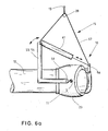
- Fig. 6a schematically shows a side view of another embodiment a tilting device 15 according to the invention
- Fig. 6b a plan view of the rotor is shown.
- a movable lever arm 56 is disposed on the free position between the opposing rotor blades 12, which is connected via a cable 57 with the opposite fastening and center point 58 of the cross member 55.
- the rope 57 is guided over a roller 20 with stop 13, on which a lifting means is struck.
- Fig. 6a the tilting device 15 between the traverse 55 of the carrier 53 and the movable lever arm 56 via a schematically drawn lifting cylinder 61, the in Fig. 6a is shown in the extended state. For the sake of better representability is in Fig. 6b the lifting cylinder 61 is not shown.
- the lifting cylinder 61 In the horizontal initial state of the rotor 10, the lifting cylinder 61 is extended, so that after raising the rotor 10 by means of the crane, the lifting cylinder 61 is retracted, whereby the relative position of the rotor 10 by a predetermined tilt angle depending on the position of the (retracted) lifting cylinder is changed.
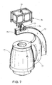
- Fig. 7 schematically shows a perspective view of a schematically indicated rotor hub 11 (omitting the connecting flanges to the rotor blades).
- a mounting bracket 71 is arranged or fixed laterally at the front and at the rear, on which a circular runway 72 and a circular arc-shaped traverse is placed.
- a trolley 73 is disposed, the trolley 73 being connected to an attachment point 13 of a lifting means of a lifting device, e.g. of a crane.
- a lifting device e.g. of a crane.
- an energy storage or drive unit 76 which may be embodied in the form of an internal combustion engine with generator for power generation or with hydraulic unit or in the form of accumulators.
- the trolley 73 has a drive 74, so that rollers 75 of the trolley 74 are driven.
- the rollers 75 engage in a ring gear or pinion or roller chain on the runway 74, so that the rotor hub 11 and a rotor with the rotor hub 11 along the circular runway 72 is pivoted about the center of gravity in a mounting position.
- the tilting movement of the rotor hub 11 is performed by the drive 74, wherein during the tilting movement, the runway 72 is moved with respect to the stationary drive or the attachment point 13.
Landscapes
- Engineering & Computer Science (AREA)
- Mechanical Engineering (AREA)
- Life Sciences & Earth Sciences (AREA)
- Sustainable Development (AREA)
- Sustainable Energy (AREA)
- Chemical & Material Sciences (AREA)
- Combustion & Propulsion (AREA)
- General Engineering & Computer Science (AREA)
- Wind Motors (AREA)
Abstract
Description
- Die Erfindung betrifft ein Verfahren zum Handhaben einer Rotornabe einer Windenergieanlage oder zum Handhaben eines Rotors einer Windenergieanlage mittels einer Hebeeinrichtung, insbesondere beim Errichten einer Windenergieanlage oder bei der Montage oder Demontage eines Rotors einer Windenergieanlage an einer Windenergieanlage. Die Erfindung betrifft ferner eine Einrichtung zur Handhabung einer Rotornabe einer Windenergieanlage oder zur Handhabung eines Rotors einer Windenergieanlage, insbesondere bei Errichtung einer Windenergieanlage oder bei der Montage oder Demontage eines Rotors einer Windenergieanlage an einer Windenergieanlage. Des Weiteren betrifft die Erfindung eine Verwendung einer Kippeinrichtung zur Errichtung oder Demontage einer Windenergieanlage.
- Um eine Windenergieanlage zu errichten, müssen zahlreiche Arbeitsschritte ausgeführt werden. Nachdem der Errichtungsort vorbereitet ist, werden verschiedene Elemente zum Errichtungsort der Windenergieanlage transportiert. Bei der Errichtung werden beispielsweise mehrere Turmabschnitte zu einem Turm zusammengebaut, anschließend wird eine Gondel mit einem Kran auf dem Turm aufgesetzt und an der Oberseite des Turmes angebracht. Anschließend wird der Rotor, bestehend aus einer Rotornabe und daran angeordneten Rotorblättern, zusammengebaut und anschließend unter Verwendung eines Krans sowie eines Hilfskrans an einer Rotorwelle an der Gondel angebracht. Alternativ hierzu wird zunächst die Rotornabe an der Rotorwelle angesetzt, so dass anschließend unter Zuhilfenahme von Kränen oder anderen Hilfsmitteln die Rotorblätter an den Flanschverbindungen des Rotors angebracht werden.
- Derzeitige Windenergieanlagen der 5 bis 6 MW-Klasse weisen Rotoren mit beträchtlichen Durchmessern und Gewichten auf. Beispielsweise beträgt der Rotordurchmesser der Windenergieanlage der Anmelderin mit der Bezeichnung 5M ungefähr 126 m. Der Zusammenbau eines Rotors durch Anbringung von Rotorblättern an einer Rotornabe erfordert bei einem Zusammenbau am Boden eine große Fläche, die frei von Hindernissen sowie eben und stabil sein muss. Beispielsweise beträgt bei einem Rotordurchmesser von 100 m die dafür benötigte freie Montagefläche mehr als 5.000 m2.
- Außerdem erfordert das Anheben eines am Boden zusammen gebauten Rotors einen großen Aufwand, da der montierte Rotor nach Anheben in der Luft entsprechend gedreht werden muss. Beispielsweise werden bei der Montage eines Rotors für die 5M-Anlage der Patentanmelderin zwei Kräne sowie (passive) Hebemittel eingesetzt, die teilweise im äußeren Rotorblattbereich angreifen und nach der Rotormontage aufwendig entfernt werden müssen.
- Ausgehend von diesem Stand der Technik besteht die Aufgabe der vorliegenden Erfindung darin, die Montage bzw. die Errichtung sowie die Demontage einer Windenergieanlage auf einfache Weise zu verbessern, wobei der konstruktive Aufwand hierfür möglichst gering gehalten werden soll. Insbesondere soll der Aufwand zur Entfernung von Hebemitteln reduziert werden.
- Gelöst wird diese Aufgabe durch ein Verfahren zum Handhaben einer Rotornabe einer Windenergieanlage oder zum Handhaben eines Rotors einer Windenergieanlage mittels einer Hebeeinrichtung, insbesondere beim Errichten einer Windenergieanlage oder bei der Montage oder Demontage eines Rotors einer Windenergieanlage an einer Windenergieanlage, wobei insbesondere eine Rotornabe oder ein Rotor mit einer Montageseite an einem Turm einer Windenergieanlage angeordnet wird oder ist, wobei die Rotornabe oder der Rotor mittels der Hebeeinrichtung angehoben oder gehalten wird, die Rotornabe im angehobenen Zustand mittels einer an der Rotornabe angreifenden Kippeinrichtung aus der ursprünglichen angehobenen Lage um einen vorbestimmten Kippwinkel gekippt wird oder der Rotor mittels einer an der den Rotorblattwurzeln der Rotorblätter des Rotors angreifenden Kippeinrichtung aus der ursprünglichen angehobenen Lage um einen vorbestimmten Kippwinkel gekippt wird.
- Vorzugsweise wird das Verfahren ausgeführt beim Errichten einer Windenergieanlage, wobei eine Rotornabe oder ein Rotor mit einer Montageseite an einem Turm einer Windenergieanlage angeordnet wird, die Rotornabe oder der Rotor mit einer Hebeeinrichtung, insbesondere Kran, angehoben wird, nach dem Anheben die Rotornabe bzw. nach dem Anheben des Rotors im angehobenen Zustand mittels einer an der Rotornabe oder am Rotor angreifenden Kippeinrichtung aus der ursprünglichen angehobenen Lage um einen vorbestimmten Kippwinkel gekippt wird.
- Die Erfindung beruht auf dem Gedanken, dass beispielsweise unter der Verwendung ausschließlich eines Krans als einzige Hebeeinrichtung eine an einem Turm bzw. an einer Gondel des Turmes zu montierende Rotornabe bzw. ein entsprechender Rotor mit Rotornabe angehoben werden und nach Anheben des Rotors bzw. der Rotornabe durch die Aktivierung einer zwischen dem Ausleger und der Rotornabe vorgesehenen Kippeinrichtung die Rotornabe bzw. der Rotor im hängenden Zustand um eine vorbestimmte Kippachse und insbesondere mit einem vorbestimmten Kippwinkel gedreht wird. Hierbei wird die Kippung der Rotornabe bzw. des Rotors unter Weglassung eines zweiten (Hilfs-)Krans ausgeführt.
- Durch die durch die Kippeinrichtung ausgeführte Verkippung beispielsweise eines waagerecht ausgerichteten Rotors wird der gesamte Rotor im angehobenen Zustand durch Betätigung bzw. unter Einsatz der Kippeinrichtung in eine zur waagerechten Ausrichtung gekippten Stellung gebracht. Um den Rotor entsprechend auszurichten, sind in einer Ausführungsform Führungsseile oder dergleichen vorgesehen, wobei diese Führungsseile bzw. -einrichtungen keine Verkippung des Rotors bewirken. Dies erfolgt durch die Kippeinrichtung.
- Um eine Kippung des Rotors bzw. der Rotornabe auszuführen, ist die Kippeinrichtung bei der Ausrichtung der an der Hebeeinrichtung bzw. an einem Anschlagpunkt angeordneten Rotornabe mit der Rotornabe und der Hebeeinrichtung, insbesondere des Auslegers bzw. des am Ausleger verlaufenden Hubseils, verbunden.
- Darüber hinaus gestattet die steuerbare Kippeinrichtung auch eine positionsgenaue Kontrolle der Kipplage der Rotornabe bzw. des Rotors im an der Hebeeinrichtung hängenden Zustand. Weiterhin ist es durch die erfindungsgemäße Kippeinrichtung möglich, die Neigung eines Rotors bzw. einer Rotornabe im Verhältnis beispielsweise zu einer Rotorwellenebene einzustellen und einen Rotor entsprechend auszurichten. Dies erfolgt insbesondere auf eine ferngesteuerte Weise, so dass in der angehobenen (waagerechten) Ausgangsposition eines Rotors durch Aktivierung bzw. Betätigung der Kippeinrichtung um einen vorbestimmten Kippwinkel gekippt wird.
- Durch den Einsatz bzw. die Verwendung der erfindungsgemäßen Kippeinrichtung wird es ferner ermöglicht, beispielsweise bei der Errichtung von Offshore-Windenergieanlagen einen Rotor an Land durch Anordnung von Rotorblättern an einer Rotornabe fertigzustellen und den fertiggestellten Rotor mittels eines Schwimmkörpers, beispielsweise einer Jack-up-Barge, zu dem Errichtungsort der Windenergieanlage zu transportieren. Am Errichtungsort werden die Beine der Jack-up-Barge ausgefahren, so dass der Schwimmkörper oberhalb des Gewässers ortsfest in eine stabile Arbeitsposition gebracht wird.
- Durch die Verwendung (ausschließlich) eines einzigen Krans, der bevorzugt ebenfalls auf dem Schwimmkörper angeordnet ist, und unter Verwendung der erfindungsgemäßen Kippeinrichtung ist es möglich, den waagerecht liegenden Rotor vom Schwimmkörper mit dem Kran anzuheben und in der angehobenen Position aus der waagerechten Position in eine gekippte Position zu verkippen, so dass der Rotor mit der Montageseite an eine Gondel einer Windenergieanlage angesetzt und befestigt werden kann. Durch die Verwendung der Kippeinrichtung ist es nicht mehr erforderlich, andere Kräne oder Hilfskräne für die Errichtung bzw. für den Kippvorgang einzusetzen, wodurch insgesamt die Montage einer Windenergieanlage insbesondere offshore vereinfacht wird. Darüber hinaus ergeben sich erhebliche Zeitvorteile bei der Errichtung einer Windenergieanlage.
- Durch eine positionsgesteuerte bzw. winkelgesteuerte Kippbewegung der Rotornabe bzw. des Rotors erfolgt eine genaue Steuerung bzw. Kontrolle, so dass bei der Montage der Neigungswinkel des Rotors auf einfache Weise verändert werden kann. Darüber hinaus wird durch den Einsatz der erfindungsgemäßen Kippeinrichtung ein weiteres Hebemittel, beispielsweise ein Hilfskran oder dergleichen, eingespart. Außerdem ist es auch nicht mehr erforderlich, weitere Hilfsmittel an einer empfindlichen Rotorblattoberfläche eines Rotors anzuschlagen, wie es derzeit im Stand der Technik erfolgt.
- Im Rahmen der Erfindung ist es selbstverständlich, dass die Kippvorgänge reversibel sind, so dass die erfindungswesentlichen Verfahrensschritte des Kippvorgangs bei der Montage einer Windenergieanlage bei Befestigung eines Rotors an einer Gondel bzw. einer Rotorwelle bei einer Demontage der Anlage umkehrbar sind, so dass bei einer Zerlegung einer installierten Anlage der Rotor nach dem Abnehmen von der Gondel oder der Rotorwelle mittels der Hebeeinrichtung gehalten wird und mittels der Kippeinrichtung aus der aufgerichteten Position in eine waagerechte Position durch Verkippung des Rotor an der Hebeeinrichtung bzw. am Kran gebracht werden kann. Wenn nachfolgend die Montage einer Windenergieanlage beschrieben ist, so ist im Rahmen der Erfindung und der Offenbarung selbstverständlich, dass auch die reversibel ausführbaren Schritte zur Demontage einer Anlage in entsprechender Weite mitgelesen werden.
- In einer Weiterbildung des Verfahrens wird vorgeschlagen, dass nach dem Anheben die gekippte Rotornabe mit ihrer Montageseite oder der gekippte Rotor mit seiner Montageseite an eine Rotornabenmontageseite des Turms oder an eine auf dem Turm angeordneten Gondel angesetzt wird. Wenn im vorliegenden Zusammenhang davon die Rede ist, dass ein Rotor oder eine Rotornabe an einem Turm einer Windenergieanlage montiert werden, so ist im Rahmen der Offenbarung damit ebenfalls umfasst, dass der Rotor oder die Rotornabe auch an einem entsprechenden Maschinenhaus oder einer Gondel auf einem Turm angeordnet werden. Dies gilt in entsprechender Weise ebenfalls für eine Demontage der Windenergieanlage.
- Der Kippvorgang eines Rotors oder der Rotornabe wird dann eingeleitet, wenn die als Aktivmittel ausgebildete Kippeinrichtung am Hebemittel der Hebeeinrichtung zur Einleitung des Kippvorgangs aktiviert oder geschaltet wird. Beispielsweise kann die Kippeinrichtung eine Hydraulik oder einen Antrieb oder dergleichen aufweisen, die zur Ausführung der Kippung betätigt wird.
- Überdies ist es von Vorteil, wenn die Rotornabe mit wenigstens einem daran angeordneten Rotorblatt mittels der Kippeinrichtung verkippt wird. Hierbei werden insbesondere das Rotorblatt bzw. die Rotorblätter mit der Rotornabe über entsprechende Flanschverbindungen miteinander verbunden, wobei die Montage des Rotors aus Rotornabe und Rotorblättern auf einer ebenen Fläche erfolgt, so dass der fertiggestellte Rotor nach der Montage in einer waagerechten Position angeordnet ist. Dabei ist die erfindungsgemäße Kippeinrichtung, die in einer Ausführungsform an der Rotornabe angesetzt wird, derart ausgelegt, dass auch Rotoren mit einem Gewicht von über 80 t, insbesondere über 100 t, im angehobenen Zustand gekippt werden.
- Darüber hinaus ist es günstig, wenn die Rotornabe oder die Rotornabe mit wenigstens einem daran angeordneten Rotorblatt (Rotor) in eine Montagebereitstellung gekippt werden. Nach dem Kippvorgang können somit die Rotornabe oder der Rotor mit der Hebeeinrichtung, beispielsweise einem Kran, an den Turm oder die Gondel, an der die Rotornabe befestigt werden soll, angenähert werden, um eine Endmontage des Rotors bzw. der Rotornabe dort auszuführen.
- Insbesondere wird der Rotor bzw. die Rotornabe mit wenigstens einem daran angeordneten Rotorblatt mittels der Kippeinrichtung verkippt.
- Zur Montage einer Windenergieanlage werden ferner der Rotor bzw. die Rotornabe mit wenigstens einem darin angeordneten Rotorblatt an dem Turm bzw. an einer Gondel des Turms angebracht. Bei einer Demontage der Windenenergieanlage wird die Rotornabe oder der Rotor von dem Turm oder von der Gondel demontiert bzw. abgenommen und anschließend mittels der Kippeinrichtung verkippt.
- Überdies ist es in einer Ausgestaltung vorteilhaft, wenn vor dem Anheben der Rotornabe die Kippeinrichtung mit der Rotornabe verbunden wird oder vor dem Anheben des Rotors die Kippeinrichtung mit dem Rotor verbunden wird. Hierbei befindet sich vorteilhafterweise die Rotornabe oder der Rotor in einem montagebereiten Zustand, so dass zur Ausführung der Montage die Kippeinrichtung an der Rotornabe angebracht wird.
- Bevorzugterweise wird die Kippeinrichtung zwischen einem Hebemittel der Hebeeinrichtung und der Rotornabe angeordnet oder die Kippeinrichtung zwischen einem Hebemittel der Hebeeinrichtung und dem Rotor angeordnet. Hierbei weist die Kippeinrichtung einen Anschlagpunkt auf, an dem das Hebemittel oder die Hebeeinrichtung angeschlagen wird. Dadurch wird unter Zwischenschaltung der Kippeinrichtung zwischen einem Ausleger oder dem Hebemittel beispielsweise eines Krans und der Rotornabe bzw. dem Rotor oder zwischen einem Hubseil der Hebeeinrichtung, z.B. Kran, und der Rotornabe bzw. Rotor die Kippeinrichtung ausgebildet, wobei die Kippeinrichtung bei der Montage passiviert ist. Erst nach Anheben der Rotornabe bzw. des Rotors wird durch Aktivierung oder Betätigung oder Schalten der Kippeinrichtung ein Kippvorgang des an einem Hebemittel eines Krans hängenden oder an einem Anschlagpunkt eines Hebemittels angeordneten Rotors im freien Raum bzw. im hängenden Zustand ausgeführt.
- Bevorzugt erfolgt der Kippvorgang mittels der frei im Raum an einem Hubseil der Hebeeinrichtung hängenden Kippeinrichtung, wobei der Rotor gegebenenfalls durch Hilfsseile gegen einfallende Windböen stabilisiert wird.
- Darüber hinaus zeichnet sich das Montageverfahren dadurch aus, dass die Rotornabe oder der Rotor unter Verwendung bzw. Einsatz eines Krans als Hebeeinrichtung angehoben wird oder ist. Hierbei ist insbesondere der Kran neben der zu errichtenden Windenergieanlage aufgebaut bzw. platziert, wobei weiter vorteilhafterweise der Kran als selbständige Einheit nicht mit der Windenergieanlage verbunden ist oder daran angeordnet ist.
- Nach der Montage des Rotors an der Gondel des Rohrturms wird der Kran nach seinem Einsatz von der Errichtungsstelle zu einer anderen Errichtungsstelle transportiert oder bewegt.
- Außerdem wird die Aufgabe gelöst durch eine Einrichtung zur Handhabung einer Rotornabe einer Windenergieanlage oder zur Handhabung eines Rotors einer Windenergieanlage, insbesondere bei Errichtung einer Windenergieanlage oder bei der Montage oder Demontage eines Rotors einer Windenergieanlage an einer Windenergieanlage, wobei die Einrichtung als Kippeinrichtung ausgebildet ist, die Kippeinrichtung Befestigungsmittel aufweist, mit denen die Kippeinrichtung an der Rotornabe und/oder an den Rotorblattwurzeln der an der Rotornabe angeordneten Rotorblätter des Rotors befestigt wird oder ist, wobei die Kippeinrichtung einen Anschlagpunkt für ein Hebemittel, insbesondere einer Hebeeinrichtung, aufweist, wobei im angehobenen Zustand der Rotornabe am Hebemittel beim Verkippen der Rotornabe mittels der am Hebemittel angeordneten Kippeinrichtung die Position der Rotornabe verändert wird oder im angehobenen Zustand des Rotors am Hebemittel beim Verkippen des Rotors mittels der am Hebemittel angeordneten Kippeinrichtung die Position der Rotornabe verändert wird.
- Hierbei wird ein Hebemittel einer Hebeeinrichtung, z.B. ein Ausleger oder ein Hubseil eines Krans, an einem Anschlagpunkt der Kippeinrichtung angeordnet, wobei die Kippeinrichtung mit Befestigungsmitteln versehen ist, so dass die Kippeinrichtung an eine Rotornabe oder einen Rotor befestigt wird oder ist, und die Kippeinrichtung derart ausgebildet ist, dass die an der Kippeinrichtung angeordnete Rotornabe bzw. der daran angeordnete Rotor im angehobenen Zustand aus der ursprünglichen angehobenen Lage in eine gekippte Position mit einem vorbestimmten Kippwinkel durch Betätigung oder Aktivierung der Kippeinrichtung gebracht wird.
- Beispielsweise verfügt eine Hebeeinrichtung über einen Ausleger und/oder ein über einen Ausleger verlaufendes Hubseil bzw. über ein, vorzugsweise an einem Ausleger angeordnetes, Hebemittel, an dem die erfindungsgemäße Kippeinrichtung an einem Anschlagpunkt befestigt wird. Als Anschlagpunkt der Kippeinrichtung wird im Rahmen der Offenbarung ein Kraftangriffspunkt für das daran angeordnete Hebemittel verstanden. Hierbei ist die Kippeinrichtung mittels einer lösbaren Verbindung an dem Anschlagpunkt angeschlagen.
- Im Rahmen der Offenbarung der Erfindung wird außerdem unter einer Hebeeinrichtung, die mit einer erfindungsgemäßen Kippeinrichtung ausgestattet bzw. verbunden wird oder ist, neben einem Kran auch ein Seil oder eine Hubplattform, beispielsweise in Form einer Jack-up-Barge oder dergleichen, verstanden.
- Bei Einsatz der Kippeinrichtung ist in einer Ausgestaltung vorgesehen, dass der Abstand des, insbesondere während des Verkippens ortsfesten, Anschlagpunktes zum Schwerpunkt der Rotornabe beim Verkippen der Rotornabe oder der Abstand des Anschlagpunktes zum Schwerpunkt des Rotors beim Verkippen des Rotors bzw. während des Kippvorgangs im Wesentlichen konstant bleibt. Hierbei wird vornehmlich die Rotornabe bzw. der Rotor im (jeweiligen) Schwerpunkt verkippt, wobei die bevorzugte Kippachse beim Verkippen der Rotornabe bzw. des Rotors im Wesentlichen horizontal verlaufend ausgebildet ist.
- Gemäß einer alternativen Weiterbildung der Kippeinrichtung wird der Abstand des, insbesondere beim Verkippen ortsfesten, Anschlagpunktes zum Schwerpunkt der Rotornabe beim Verkippen der Rotornabe oder der Abstand des Anschlagpunktes zum Schwerpunkt des Rotors beim Verkippen des Rotors bzw. während des Kippvorgangs je nach Ausgestaltung der Kippeinrichtung verändert, insbesondere vergrößert oder verkleinert. Dabei kann die, insbesondere horizontal verlaufende, Kippachse, um die der Verkippvorgang des Rotors oder der Rotornabe ausgeführt wird, außerhalb des Schwerpunkts der Rotornabe bzw. des Rotors liegen, wobei die Kippachse in Abhängigkeit der Kippstellung der Rotornabe oder des Rotors ihre Lage verändern kann, d.h. wandert, wobei insbesondere die bevorzugte horizontale Ausrichtung der Kippachse unverändert bleibt.
- Um eine Verkippung oder eine Verschränkung des Rotors oder der Rotornabe im angehobenen Zustand sicher auszuführen, ist weiterhin in einer Ausgestaltung vorgesehen, dass das Befestigungsmittel der Kippeinrichtung als Rahmen, insbesondere Anbaurahmen, oder als Gestell oder als Befestigungsbügel oder als Adapter ausgebildet ist. Hierdurch wird der Rotor oder die Rotornabe lösbar mit der Kippeinrichtung gut verbunden, um eine Verkippung anschließend auszuführen.
- Dazu ist weiter vorgesehen, dass am Befestigungsmittel der Kippeinrichtung ein Tragbügel oder ein Hebearm oder ein Schwenkbügel, insbesondere Schwenkrahmen, oder Schwenkgestell oder eine, insbesondere gekrümmte, Führungsschiene, vorzugsweise Traverse, angeordnet oder vorgesehen ist, so dass unter Verwendung von diesen genannten Einrichtungen und insbesondere weiter in Kombination bzw. unter Einsatz eines Antriebs oder Aktors die angehobene Rotornabe bzw. der angehobene Rotor verkippt werden.
- Weiterhin kann die Kippeinrichtung auch einen Hebearm und/oder einen Hebelarm aufweisen, wobei für die Verkippung von Rotor oder Rotornabe der Hebearm oder der Hebelarm beweglich oder bewegbar an der Rotornabe oder an einem an der Rotornabe vorgesehenen Befestigungsbauteil bzw. -mittel der Kippeinrichtung angeordnet sind oder werden.
- Außerdem ist es günstig in einer Ausgestaltung der Kippeinrichtung, wenn die Kippeinrichtung einen Antrieb und/oder einen Aktor aufweist. Vorzugsweise ist der Aktor als Hubzylinder, insbesondere Teleskopzylinder, oder als Seilwinde oder als Seilzug, insbesondere mit Seilverkürzung/Seilverlängerung, oder als rotatorischer Antrieb, insbesondere mit einem Antriebsritzel, ausgebildet.
- Überdies ist in einer Weiterbildung der Einrichtung der Antrieb im Eingriff mit der Führungsschiene, um durch Betätigung des Antriebs bzw. des Motors die Verkippung der Rotornabe bzw. des Rotors mittels der Kippeinrichtung einzuleiten bzw. den Kippvorgang gezielt von außen zu beeinflussen bzw. zu steuern.
- Um eine exakte Bewegungsführung bei dem Kippvorgang auszuführen, ist es ferner bevorzugt, wenn die Führungsschiene, in die ein Antrieb(smotor) eingreift, mit einem Zahnkranz oder mit einem Bolzenkranz oder einer Rollenkette ausgebildet ist.
- Eine einfache Ausbildung und Handhabung der Kippeinrichtung ergibt sich dadurch, dass der Antrieb am Hebemittel der Hebeeinrichtung oder Anschlagpunkt oder an der Führungsschiene angeordnet ist oder wird.
- Darüber hinaus wird die Aufgabe der Erfindung gelöst durch eine Verwendung einer Kippeinrichtung zur Errichtung oder Demontage einer Windenergieanlage, wobei die Kippeinrichtung wie voranstehend beschrieben ausgebildet ist, insbesondere unter Verwendung einer Hebeeinrichtung.
- Durch die Verwendung einer Kippeinrichtung bei oder zur Errichtung oder Demontage einer Windenergieanlage ist es möglich, dass mittels einer Hebeeinrichtung eine Rotornabe oder ein Rotor angehoben wird oder ist, und insbesondere die Rotornabe oder der Rotor an einem Turm einer Windenergieanlage angeordnet wird oder ist, wobei die Kippeinrichtung zwischen dem Hebemittel beispielsweise an einem Ausleger der Hebeeinrichtung oder einem Hubseil der Hebeeinrichtung und der Rotornabe bzw. dem Rotor angeordnet wird, so dass die Rotornabe oder der Rotor mittels der Kippeinrichtung um einen vorbestimmten Kippwinkel aus der ursprünglichen angehobenen Lage durch oder nach Betätigung oder Aktivierung der Kippeinrichtung gekippt wird oder ist.
- Weitere vorteilhafte Ausgestaltungen der erfindungsgemäßen Kippeinrichtung sind voranstehend ausführlich beschrieben, so dass auf die obigen Ausführungen ausdrücklich verwiesen wird. Im Rahmen der Offenbarung ist auch eine Kombination einer Hebeeinrichtung, beispielsweise in Gestalt eines Hebekrans, einer Hubplattform, z.B. Jack-up-Barge oder dergleichen, mit einer erfindungsgemäßen Kippeinrichtung beschrieben.
- Im erfindungsgemäßen Sinne wird die Kippeinrichtung temporär zur Montage oder Demontage von Bauteilen einer Windenergieanlage eingesetzt, wobei insbesondere die Bauteile, z.B. Rotoren oder Rotornaben, in eine montagebereite Position gebracht werden, nachdem die Bauteile sich in der angehobenen Position befinden und durch Betätigung der Kippeinrichtung in eine gekippte Stellung gebracht werden, wobei es erfindungsgemäß nicht mehr erforderlich ist, andere Hebemittel zu verwenden, um einen Rotor oder ein entsprechendes Bauteil in eine montagebereite Position mit einem vorbestimmten Neigungswinkel oder Kippwinkel zu bringen.
- Die Erfindung wird nachstehend ohne Beschränkung des allgemeinen Erfindungsgedankens anhand von Ausführungsbeispielen unter Bezugnahme auf die Zeichnungen beschrieben, wobei bezüglich aller im Text nicht näher erläuterten erfindungsgemäßen Einzelheiten ausdrücklich auf die Zeichnungen verwiesen wird. Es zeigen:
- Fig. 1 a, Fig. 1b
- eine Querschnittsdarstellung eines an einem Kran hängenden Rotors in einer im Wesentlichen waagerechten Lage und in einer gekippten Montageposition;
- Fig. 2a, Fig. 2b
- schematisch in einer Seitenansicht jeweils weitere Ausführungsformen eines an einem Kran hängenden Rotors;
- Fig. 3
- in einer schematischen Teilansicht einen Bestandteil einer erfindungsgemäßen Kippeinrichtung;
- Fig. 4a, Fig. 4b
- eine Seitenansicht bzw. Draufsicht auf einen Rotor;
- Fig. 5a, Fig.5b
- eine Seitenansicht und eine Draufsicht auf einen Rotor und
- Fig. 6a, Fig. 6b
- eine Seitenansicht und eine Draufsicht auf einen Rotor und
- Fig. 7
- eine schematische, perspektivische Darstellung einer Rotornabe mit einer Kippeinrichtung.
- In den folgenden Figuren sind jeweils gleiche oder gleichartige Elemente bzw. entsprechende Teile mit denselben Bezugsziffern versehen, so dass von einer entsprechenden erneuten Vorstellung abgesehen wird.
-
Fig. 1 a zeigt schematisch in einer Seitenansicht einen Rotor 10 einer Windenergieanlage im angehobenen Zustand, wobei der Rotor 10, mit einer Rotornabe 11, die im Querschnitt schematisch dargestellt ist, und einem an der Rotornabe 11 angeordneten Rotorblatt 12 ausgebildet ist. - Insbesondere sind an der Rotornabe 11 mehrere, vorzugsweise drei, Rotorblätter 12 gleichmäßig angeordnet und mit Flanschverbindungen mit der Rotornabe 11 verbunden. Aus Gründen der besseren Darstellbarkeit wurde von der Einzeichnung weiterer Rotorblätter abgesehen.
- Der Rotor 10 wurde im waagerechten Zustand auf einer freien ebenen Fläche montiert. Dies kann beispielsweise am Errichtungsort einer Windenergieanlage erfolgen. Werden die Windenergieanlagen offshore errichtet, ist es beispielsweise möglich, dass die Rotoren 10 an Land im waagerechten Zustand gefertigt werden und anschließend mittels eines Schwimmkörpers zum Errichtungsort transportiert werden. Am Errichtungsort selbst werden die Rotoren 10 aus der ursprünglichen waagerechten Position mittels eines Krans, der über einen Ausleger und ein Hubseil verfügt, angehoben, so dass der Rotor 10 in einer im Wesentlichen waagerechten Position an einem Haken 14 oder einer Hakenflasche oder dergleichen hängt. Typischerweise haben die zu installierenden Rotoren einer Windenergieanlage der 5 bis 6 Megawatt-Klasse ein Gewicht von 120 Tonnen und mehr.
- Als Kräne bzw. Hebeeinrichtungen werden beispielsweise Kräne verwendet, wie sie in
DE 100 28 513 A1 beschrieben sind. Auf dieses Dokument wird im Hinblick auf weitere Details zu Kränen ausdrücklich hingewiesen. InDE 100 28 513 A1 sind ein Verfahren und eine Vorrichtung zur Montage einer Windkraftanlage unter Verwendung von Kränen offenbart. - Erfindungsgemäß ist zwischen der Rotornabe 11 und dem Haken 14 eine Kippeinrichtung 15 ausgebildet, die vor Anheben des Rotors 10 an der Rotornabe 11 fixiert wird. Hierbei weisen sowohl die Rotornabe 11 als auch die Kippeinrichtung 15 entsprechende Fixierungsmittel bzw. Befestigungseinrichtungen auf.
- Die Kippeinrichtung 15 verfügt über einen Befestigungsadapter 16, der lösbar fest mit dem Rotor 10 bzw. der Rotornabe 11 verbunden wird. Hierzu sind beispielsweise Schraubverbindungen zwischen dem Befestigungsadapter 16 und der Rotornabe 11 vorgesehen. Beispielsweise kann der Befestigungsadapter 16 als Ausbaurahmen mit entsprechenden Befestigungsmitteln ausgebildet sein.
- Darüber hinaus verfügt die Kippeinrichtung 15 über einen verschwenkbaren Hebelarm 18, der mittels eines Bolzens 17 schwenkbar am Befestigungsadapter 16 oder eine Basis angeordnet ist. Hierbei ist der Hebelarm 18 um den Bolzen 17 sowie um eine kollinear zum Bolzen 17 ausgebildete Schwenkachse verschwenkbar bzw. verkippbar. Auf der rückwärtigen Seite der Kippeinrichtung 15 ist ein verschwenkbarer Hydraulikzylinder 19 bzw. Teleskopzylinder zwischen dem einen Ende des Befestigungsadapters 16 und dem oberen Kopfende des Hebelarms 18 angeordnet.
- Der Hebelarm 18 weist an dem dem Haken 14 zugewandten Ende eine kopfartige Verbreiterung oberhalb des Schwerpunkts S auf, wobei das eine Ende der kopfartigen Verbreiterung über einen Schäkel 21 und ein Seil 22 mit dem Haken 14 verbunden ist. An dem dem Schäkel 21 gegenüberliegenden Ende des Hebelarms 18 ist der Hydraulikzylinder 19 mit dem Hebelarm 18 verbunden. Der Hebelarm 18 ist mittels eines Bolzens oder dergleichen am Anschlagpunkt 13 am Sockel 21, der Bestandteil eines Hebemittels eines Krans oder einer anderen Hebeeinrichtung ist, angeschlagen.
-
Fig. 1a zeigt den Hydraulikzylinder 19 in einer ausgefahrenen Position, so dass der Schäkel 21 bei waagerechter Anordnung des Rotors 10 oberhalb des schematisch eingezeichneten Schwerpunktes S des Rotors 10 angeordnet ist. Im ausgefahrenen Zustand des Hydraulikzylinders 19 wird der Rotor 10 in seiner im Wesentlichen horizontalen Lage angehoben. - In einer entsprechenden Höhe wird die Hydraulik bzw. Steuerung für den Hydraulikzylinder 19 bzw. die Kippeinrichtung aktiviert, so dass der Rotor 10 durch Zurückfahren des Hydraulikzylinders 19 bei gleichzeitiger Verkippung des Rotors 10 in eine entsprechend gekippte Lage bei freihängendem Zustand des Rotors 10 am Haken 14 des eingesetzten Krans gebracht wird.
-
Fig. 1 b zeigt den Rotor 10 in einer entsprechend gekippten aufrecht ausgerichteten Position, so dass beispielsweise der Rotor 10 mit seiner Rotornabe 11 an eine entsprechende Rotorwelle an einer Gondel angehoben wird und dort mittels des verwendeten Krans ausgerichtet und anschließend mit seiner Rückseite an einer Gondel oder am Turm befestigt wird. Hierbei wird beispielsweise die Rückseite 23 der Rotornabe 11 an einen entsprechenden Flansch angeflanscht. - In einer Alternative ist anstelle des Hebelarms 18 ein Schwenkrahmen oder dergleichen am Befestigungsadapter 16 angeordnet.
- Im Rahmen der Erfindung ist es möglich, dass bei Verwendung derselben Elemente einer Kippeinrichtung 15 eine Kippeinrichtung zur Montage einer Windenergieanlage sich in der Anordnung der Elemente von einer Kippeinrichtung zur Demontage der Windenergieanlage unterscheidet, um eine einfache Handhabung der Kippeinrichtung zu erreichen.
- Die Verkippung bzw. die Verschwenkung des Rotors 10 in der angehobenen Position erfolgt ausschließlich durch die Betätigung der Kippeinrichtung 15, so dass durch Ausführung einer Kippbewegung mittels der Kippeinrichtung 15 der Rotor 10 in eine montagebereite Position zur Montage an einem Turm gebracht wird bzw. ausgerichtet wird.
-
Fig. 2a zeigt ein weiteres Ausführungsbeispiel mit einer anderen Kippeinrichtung 15. Hierbei befindet sich der Rotor 10 im angehobenen Zustand, wobei der Rotor 10 im Wesentlichen horizontal ausgerichtet ist. An einer entsprechenden Seite der Rotornabe 11 ist ein gekrümmter Hebearm 25 auf der Vorderseite der Rotornabe 11 und im Bereich der Rückseite 23 der Rotornabe 11 mit der Rotornabe 11 lösbar verbunden. - Der Hebearm 25 ist mit einer Krümmung ausgebildet, wobei am Ende des Hebearms 25, der dem Haken 14 zugewandt ist oder wird, bzw. dem oberen Ende des Hebearms 25 ein Seil 26 angelenkt und am Anschlagpunkt 13 des Hebemittels angeschlagen ist. Das Seil 26 verläuft vom oberen Anschlagpunkt des Hebearms 25 unter Zwischenschaltung eines Verstellelements 27 zum Anschlagpunkt 13 am Haken 14, der am (nicht dargestellten) Kran bzw. an einem nicht gezeigten Kranauslegerarm angeordnet ist. Ferner ist am Anschlagpunkt 13 ein zweites Seil 24 angeschlagen, das eine konstante Länge aufweist, und mit einem beweglich am Hebearm 25 angeordneten Arm 28, der gegenüber dem oberen Ende des Hebearms 25 angeordnet ist, verbunden ist.
- Durch das Verstellelement 27, das beispielsweise als Winde oder Kettenzug oder Spindel oder auch als hydraulischer Zylinder ausgebildet ist, wird die Länge des Seils 26 verlängert, dass der Rotor 10 dadurch in eine Kipplage gebracht wird, wobei der Rotor 10 in eine aufgerichtete, vorzugsweise zur Montage bereite, Position gekippt wird. Anschließend wird der Rotor 10 mit seiner Rückseite 23 an einer Gondel angesetzt bzw. angeflanscht. Nach der Montage des Rotors 10 wird der Hebearm 25 sowie das Seil 26, das Verstellelement 27 zusammen mit dem beweglichen Arm 28 vom Rotor 10 demontiert.
- Bei dem in
Fig. 2b gezeigten Ausführungsbeispiel einer Kippeinrichtung sind die Seile 24, 26 gegenüber dem inFig. 2a gezeigten Ausführungsbeispiel vertauscht. Entsprechend wurde auch das Verstellelement 27, beispielsweise eine Seilwinde, ebenfalls auf der anderen Seite angeordnet. Um eine Verkippung des Rotors 10 auszuführen, wird bei dem inFig. 2b dargestellten Ausführungsbeispiel die Länge des Seils 26 mittels des Verstellelements 27 verkürzt. Hierbei wird ebenfalls der Abstand zwischen dem Anschlagpunkt 13 und dem Schwerpunkt S des Rotors 10 verkürzt. Bei dem inFig. 2a gezeigten Ausführungsbeispiel wird beim Verkippen des Rotors 10 durch Verlängerung der Seillänge des Seils 26 der Abstand zwischen dem Anschlagpunkt 13 und dem Schwerpunkt S vergrößert. - Eine Verkippung mit Vergrößerung des Schwerpunktabstands zum Anschlagpunkt erfordert vorteilhaft keine externe Antriebsenergie, z.B. kann Öl in einem Hydraulikzylinder über ein Hydraulikventil und eine Blende in einen drucklosen Tank abgelassen werden. Wird der Schwerpunktabstand bei der Verkippung in gezeigter Anordnung reduziert, erfordert dieses eine Antriebsenergie, die beispielsweise durch einen Verbrennungsmotor, Akkumulatoren oder in einem hydraulischen Druckspeicher zur Verfügung gestellt werden kann.
-
Fig. 3 zeigt eine schematische Seitenansicht eines brückenartigen oder wangenartigen Bauteils 31 als Bestandteil einer weiteren erfindungsgemäßen Kippeinrichtung 15. Das Bauteil 31 verfügt über Anschlüsse 32, 33, mittels derer das Bauteil 31 an eine Rotornabe eines Rotors angeordnet wird. Hierbei ist die Kontaktstelle des Anschlusses 32 im rückseitigen Bereich und der Anschluss 33 im vorderseitigen Bereich der Rotornabe befestigt. - Das Bauteil 31 verfügt über eine armförmige gekrümmte Verlängerung 34, die im Inneren ein gebogenes kreisförmiges Zahnkranzsegment 35 aufweist. Das Zahnkranzsegment 35 ist derart gebogen, dass der Abstand bzw. der Radius R zu der Innenseite des Zahnkranzsegments 35 bezogen auf den Rotorschwerpunkt S konstant ist. Die Zähne des Zahnkranzsegments 35 befinden sich in Eingriff mit einem Antriebsritzel 36 eines Anschlussbauteils 37. Um das Anschlussteil 38 exakt auf das bzw. entlang des Zahnkranzsegments 35 zu führen bzw. zu bewegen, weist das Anschlussteil 38 ein Gegenlager in Form einer Tragrolle 41 auf, die auf der kreisbogenförmigen bzw. gekrümmten Innenseite des Zahnkranzsegments 35 abrollt, so dass zwischen der Tragrolle 41 und dem Antriebsritzel 36 das Zahnkranzsegment 35 angeordnet ist.
- Das Antriebsritzel 36 wird mittels eines Antriebs in Rotation versetzt, so dass durch die Rotation des Antriebsritzels 36 das Anschlussbauteil 37 auf einer Kreisbogenbahn verfahren wird, wobei die Tragrolle 41 zur Übertragung der Hubkraft auf der kreisförmigen Innenseite des Zahnkranzsegments 35 abrollt. Beim Verkippen bzw. Verschwenken bleibt der Abstand zwischen dem Anschlagpunkt des Hebemittels und dem Schwerpunkt des Rotors der Rotornabe im Wesentlichen konstant. Das Anschlussteil 37 ist auf per se bekannte Weise mit einem Hebemittel in Form eines Hubseil bzw. einem Lasthaken eines Krans in einem Anschlagpunkt verbunden, wenn das Bauteil 31 an eine Rotornabe angebaut wird oder nachdem es angebaut worden ist.
- Befindet sich eine hochzuhebende und zu verkippende Rotornabe mit ihrer Rückseite auf einem Boden, so wird das Anschlussteil 37 im Bereich des linken Anschlags 38 des Zahnkranzsegments 35 angeordnet. Soll die Rotornabe bzw. der Rotor im hängenden Zustand verkippt bzw. gedreht werden, so wird das Anschlussteil 37 durch Bewegung des Antriebsritzels 36 in Richtung des zweiten Anschlags 39 bewegt, bis die Rotornabe bzw. der Rotor einen vorbestimmten Kippwinkel einnehmen.
- Als Antriebe für das Antriebsritzel 36 ist es beispielsweise möglich, dass hierfür elektrische oder hydraulische Antriebe oder auch elektrische Getriebemotoren vorgesehen sind.
- In
Fig. 4a und4b sind eine Querschnittsdarstellung sowie eine Draufsicht auf einen Rotor 10 dargestellt, wobei zur Darstellung erfindungswesentlicher Elemente von der Darstellung anderer Bauteile des Rotors 10 abgesehen worden ist. Um den Rotor 10 im angehobenen Zustand zu verkippen, wird vor dem Anhebevorgang die Kippeinrichtung 15 in Form einer kreisbogenförmigen Laufbahn 42 oder Gleitschiene auf der Vorderseite der Rotornabe 11 montiert. Hierbei verläuft im Inneren der Laufbahn 42 ein Aufhängeteil 43, z.B. eine Laufkatze oder dergleichen. Die Laufbahn 42 wird darüber hinaus, wie ausFig. 4b (Draufsicht) ersichtlich ist, seitlich über Befestigungsarme 44, 45 zwischen den Rotorblättern 12 an der Rotornabe 11 fixiert. - Die Lauffläche 42 bzw. gekrümmte Gleitschiene ist mittels Befestigungsarmen 44, 45, 62, 63 an der Rotornabe 11 befestigt. Nach Gebrauch der Kippeinrichtung bzw. der Laufbahn 42 und dem Aufhängeteil 43 wird die Laufbahn 42 mitsamt der Befestigungsarme 44, 45, 62, 63 von der Rotornabe montiert, so dass anschließend an dem Rotor 10 im Bereich der Rotornabe 11 eine Nabenverkleidung 65 in Form eines so genannten Spinners an den Spinnerbefestigungsvorrichtungen 66, 67 befestigt wird. Ein Teil der Nabenverkleidung 65 ist in
Fig. 4a teilweise dargestellt. - Nachdem die Kippeinrichtung mit der gekrümmten Laufbahn 42 an der Rotornabe befestigt ist, wird an einem Anschlagpunkt des Aufhängeteils, z.B. eine Laufkatze mit einem Antrieb, ein Hebemittel angeordnet.
- Durch einen entsprechenden motorischen Antrieb für das Aufhängeteil 43 wird im angehobenen Zustand das Aufhängeteil 43 entlang beispielsweise eines Zahnkranzes oder dergleichen auf oder in der Laufbahn 42 bewegt, wodurch der gesamte Rotor 10 um eine Kippachse verkippt wird und in eine montagebereite Kippstellung gebracht wird. Anschließend wird der Rotor an eine Rotorwelle auf einer Gondel angesetzt und montiert.
-
Fig. 5a und5b zeigen, dass die kreisbogenförmige Laufbahn 42 mittels einer Bolzenverbindung 46 direkt mit der Rotornabe bzw. einem Verbindungsstück 47 der Rotornabe 11 verbunden wird. Um die Kippeinrichtung für den Kippvorgang zu stabilisieren, ist außerdem vorgesehen, dass die Laufbahn 42 mit Hilfe von unter der Nabenverkleidung 65 befindlichen, (nicht sichtbaren) Befestigungsarmen 44, 45 seitlich zwischen den anderen Rotorblättern 12 fixiert wird. Die Nabenverkleidung 65 kann so vor dem Anheben des Rotors weitgehend montiert sein, wobei bevorzugt die Befestigungsarme 44, 45 nach Anbringen der Kippeinrichtung 15 mit Verkleidungssegmenten 48, 49 abgedeckt werden. - Bei einem dreiblättrigen Rotor 10 erfolgt die Verkippung derart, dass insbesondere ein Rotorblatt nach unten gerichtet positioniert ist, während die beiden anderen Rotorblätter seitlich nach oben von der Rotornabe wegweisen. Der Rotor befindet sich dann in der so genannten Y-Stellung.
- Bei dem in
Fig. 5a gezeigten Ausführungsbeispiel ist die Laufbahn 42 bzw. Gleitschiene unmittelbar mit dem Verbindungsstück 47 verbunden, wodurch sich eine kleinbauende Anordnung einer Kippeinrichtung ergibt. Hierbei ist das Verbindungsstück 47 als Anschlagmittel für den Transport der Rotornabe 11 an dem Nabeneinstiegsflansch 68 der Rotornabe angebracht. Nach Montage bzw. Demontage des Rotors 10 wird die Laufbahn 42 sowie das Verbindungsstück 47 von der Rotornabe demontiert, wobei die Befestigungsarme 62, 63 an der Rotornabe verbleiben oder ebenfalls demontiert werden können. Anschließend wird nur das fehlende Verkleidungssegment 48, 49 der Nabenverkleidung 65 an den Spinnerbefestigungvorrichtungen 66, 67 montiert. - Bei dem in den
Figuren 5a ,5b gezeigten Ausführungsbeispiel einer Kippeinrichtung ist die Kippeinrichtung innerhalb des Spinners mit der Rotornabe verbunden, während gemäß den inFig. 4a ,4b gezeigten Ausführungsbeispielen die Kippeinrichtung außerhalb des Spinners angeordnet ist. Nach einer Montage des Rotors 10 an einem Turm bzw. einer Gondel, wobei der Wellenflansch mit der Rotorwelle verbunden wird, wird die Kippeinrichtung abmontiert, so dass die Nabenverkleidung 65 anschließend an den Befestigungsvorrichtungen 66, 67 befestigt wird. - Besonders bevorzugt sind die Befestigungsarme 44, 45, 62, 63 und die Befestigungsvorrichtungen 66, 67 ein und die selben Bauteile und verbleiben an der Rotornabe. Alternativ werden vorteilhaft die Befestigungsarme 44, 45, 62, 63 demontiert und die Befestigungsvorrichtungen 66, 67 werden an die gleichen Befestigungspunkte an der Rotornabe befestigt.
-
Fig. 6a zeigt schematisch eine Seitenansicht eines weiteren Ausführungsbeispiels einer erfindungsgemäßen Kippeinrichtung 15. InFig. 6b ist eine Draufsicht auf den Rotor gezeigt. - Beidseitig von einem Rotorblatt 12 ist mittels Befestigungsmitteln 51, 52 je ein in der Seitenansicht L-förmiger Tragarm 53, 54 fixiert. Zwischen den Tragarmen 53, 54 ist eine entsprechende Traverse 55 angeordnet. Gegenüber von der Traverse 55 ist auf der freien Stelle zwischen den gegenüberliegenden Rotorblättern 12 ein beweglicher Hebelarm 56 angeordnet, der über ein Seil 57 mit dem gegenüberliegenden Befestigungs- und Mittelpunkt 58 der Traverse 55 verbunden ist. Hierbei wird das Seil 57 über eine Rolle 20 mit Anschlagpunkt 13 geführt, an der ein Hebemittel angeschlagen wird.
- Darüber hinaus verfügt die Kippeinrichtung 15 zwischen der Traverse 55 des Trägers 53 und dem beweglichen Hebelarm 56 über einen schematisch eingezeichneten Hubzylinder 61, der in
Fig. 6a im ausgefahrenen Zustand dargestellt ist. Aus Gründen der besseren Darstellbarkeit ist inFig. 6b der Hubzylinder 61 nicht dargestellt. - Im waagerecht ausgerichteten Anfangszustand des Rotors 10 ist der Hubzylinder 61 ausgefahren, so dass nach dem Anheben des Rotors 10 mittels des Krans der Hubzylinder 61 eingefahren wird, wodurch die relative Lage des Rotors 10 um einen vorbestimmten Kippwinkel in Abhängigkeit der Stellung des (eingefahrenen) Hubzylinders verändert wird.
-
Fig. 7 zeigt schematisch eine perspektivische Darstellung einer schematisch angedeuteten Rotornabe 11 (unter Weglassung der Verbindungsflansche zu den Rotorblättern). An der Rotornabe 11 ist seitlich an der Vorderseite und an der Hinterseite ein Befestigungsbügel 71 angeordnet bzw. befestigt, auf den eine kreisförmige Rollbahn 72 bzw. eine kreisbogenförmige Traverse aufgesetzt ist. - Am oberen Ende der Rollbahn 72 ist eine Laufkatze 73 angeordnet, wobei die Laufkatze 73 mit einem Anschlagpunkt 13 eines Hebemittels einer Hebeeinrichtung, z.B. eines Krans, verbunden ist. Unter dem Anschlagpunkt 13 befindet sich ein Energiespeicher bzw. Antriebsaggregat 76, welches in Form eines Verbrennungsmotors mit Generator zur Stromerzeugung oder mit Hydraulikaggregat oder auch in Form von Akkumulatoren ausgeführt sein kann.
- Die Laufkatze 73 verfügt über einen Antrieb 74, so dass Rollen 75 der Laufkatze 74 angetrieben werden. Die Rollen 75 greifen in einen Zahnkranz oder Bolzenkranz oder eine Rollenkette auf der Rollbahn 74 ein, so dass die Rotornabe 11 bzw. ein Rotor mit der Rotornabe 11 entlang der kreisförmigen Rollbahn 72 um den Schwerpunkt herum in eine Montageposition geschwenkt wird. Hierbei wird die Kippbewegung der Rotornabe 11 durch den Antrieb 74 ausgeführt, wobei während der Kippbewegung die Rollbahn 72 in Bezug auf den ortsfesten Antrieb bzw. den Anschlagpunkt 13 bewegt wird.
-
- 10
- Rotor
- 11
- Rotornabe
- 12
- Rotorblatt
- 13
- Anschlagpunkt
- 14
- Haken
- 15
- Kippeinrichtung
- 16
- Befestigungsadapter
- 17
- Bolzen
- 18
- Hebelarm
- 19
- Hydraulikzylinder
- 20
- Rolle
- 21
- Schäkel
- 22
- Seil
- 23
- Rückseite
- 24
- Seil
- 25
- Hebearm
- 26
- Seil
- 27
- Verstellelement
- 28
- Arm
- 31
- Bauteil
- 32
- Anschluss
- 33
- Anschluss
- 34
- Arm
- 35
- Zahnkranzsegment
- 36
- Antriebsritzel
- 37
- Anschlussteil
- 38
- Anschlag
- 39
- Anschlag
- 41
- Rolle
- 42
- Laufbahn
- 43
- Aufhängeteil
- 44
- Befestigungsarm
- 45
- Befestigungsarm
- 46
- Bolzenverbindung
- 47
- Verbindungsstück
- 48
- Verkleidungssegment
- 49
- Verkleidungssegment
- 51
- Befestigungsmittel
- 52
- Befestigungsmittel
- 53
- Träger
- 54
- Tragarm
- 55
- Traverse
- 56
- Hebelarm
- 57
- Seil
- 58
- Mittelpunkt
- 61
- Hubzylinder
- 62
- Befestigungsarm
- 63
- Befestigungsarm
- 65
- Nabenverkleidung
- 66
- Befestigungsvorrichtung
- 67
- Befestigungsvorrichtung
- 71
- Befestigungsbügel
- 72
- Rollbahn
- 73
- Laufkatze
- 74
- Antrieb
- 75
- Rolle
- 76
- Energiespeicher / Antriebsaggregat
- S
- Schwerpunkt
- R
- Radius
Claims (15)
- Verfahren zum Handhaben einer Rotornabe (11) einer Windenergieanlage oder zum Handhaben eines Rotors (10) einer Windenergieanlage mittels einer Hebeeinrichtung, insbesondere beim Errichten einer Windenergieanlage oder bei der Montage oder Demontage eines Rotors (11) einer Windenergieanlage an einer Windenergieanlage, wobei insbesondere eine Rotornabe (11) oder ein Rotor (10) mit einer Montageseite an einem Turm einer Windenergieanlage angeordnet wird oder ist, wobei die Rotornabe (11) oder der Rotor (10) mittels der Hebeeinrichtung angehoben oder gehalten wird, die Rotornabe (11) im angehobenen Zustand mittels einer an der Rotornabe (11) angreifenden Kippeinrichtung (15) aus der ursprünglichen angehobenen Lage um einen vorbestimmten Kippwinkel gekippt wird oder der Rotor (10) mittels einer an der den Rotorblattwurzeln der Rotorblätter des Rotors (10) angreifenden Kippeinrichtung (15) aus der ursprünglichen angehobenen Lage um einen vorbestimmten Kippwinkel gekippt wird.
- Verfahren nach Anspruch 1, dadurch gekennzeichnet, dass die Kippeinrichtung (15) zur Einleitung des Kippvorgangs aktiviert oder geschaltet wird.
- Verfahren nach Anspruch 1 oder 2, dadurch gekennzeichnet, dass die Rotornabe (11) oder der Rotor (10) am Turm oder an einer Gondel des Turms angebracht werden oder vom Turm oder von der Gondel demontiert werden, wobei insbesondere vor dem Anheben der Rotornabe (11) die Kippeinrichtung (15) mit der Rotornabe (11) verbunden wird oder vor dem Anheben des Rotors (10) die Kippeinrichtung (15) mit dem Rotor (10) verbunden wird.
- Verfahren nach einem der Ansprüche 1 bis 3, dadurch gekennzeichnet, dass die Kippeinrichtung (15) zwischen einem Hebemittel der Hebeeinrichtung und der Rotornabe (11) angeordnet wird oder die Kippeinrichtung (15) zwischen einem Hebemittel der Hebeeinrichtung und dem Rotor (10) angeordnet wird.
- Verfahren nach einem der Ansprüche 1 bis 4, dadurch gekennzeichnet, dass nach dem Anheben die gekippte Rotornabe (11) mit ihrer Montageseite oder der gekippte Rotor (10) mit seiner Montageseite an eine Rotornabenmontageseite des Turms oder an eine auf dem Turm angeordneten Gondel angesetzt wird.
- Verfahren nach einem der Ansprüche 1 bis 3, dadurch gekennzeichnet, dass die Rotornabe (11) oder der Rotor (10) unter Verwendung eines Krans als Hebeeinrichtung angehoben wird.
- Einrichtung (15) zur Handhabung einer Rotornabe (11) einer Windenergieanlage oder zur Handhabung eines Rotors (10) einer Windenergieanlage, insbesondere bei Errichtung einer Windenergieanlage oder bei der Montage oder Demontage eines Rotors einer Windenergieanlage an einer Windenergieanlage, wobei die Einrichtung als Kippeinrichtung (15) ausgebildet ist, die Kippeinrichtung (15) Befestigungsmittel aufweist, mit denen die Kippeinrichtung (15) an der Rotornabe (11) und/oder an den Rotorblattwurzeln der an der Rotornabe (11) angeordneten Rotorblättern des Rotors (10) befestigt wird oder ist, wobei die Kippeinrichtung (15) einen Anschlagpunkt (13) für ein Hebemittel, insbesondere einer Hebeeinrichtung, aufweist, wobei im angehobenen Zustand der Rotornabe (11) am Hebemittel beim Verkippen der Rotornabe (11) mittels der am Hebemittel angeordneten Kippeinrichtung (15) die Position der Rotornabe (11) verändert wird oder im angehobenen Zustand des Rotors (11) am Hebemittel beim Verkippen des Rotors (10) mittels der am Hebemittel angeordneten Kippeinrichtung (15) die Position der Rotornabe (11) verändert wird.
- Einrichtung (15) nach Anspruch 7, dadurch gekennzeichnet, dass der Abstand des Anschlagpunktes (13) zum Schwerpunkt (S) der Rotornabe (11) beim Verkippen der Rotornabe (11) oder der Abstand des Anschlagpunktes (13) zum Schwerpunkt (S) des Rotors (10) beim Verkippen des Rotors (10) im Wesentlichen konstant bleibt oder der Abstand des Anschlagpunktes (13) zum Schwerpunkt (S) der Rotornabe (11) beim Verkippen der Rotornabe (11) oder der Abstand des Anschlagpunktes (13) zum Schwerpunkt (S) des Rotors (10) beim Verkippen des Rotors (10) verändert, insbesondere vergrößert oder verkleinert, wird.
- Einrichtung (15) nach Anspruch 7 oder 8, dadurch gekennzeichnet, dass das Befestigungsmittel als Rahmen, insbesondere Anbaurahmen, oder als Gestell oder als Befestigungsbügel oder als Adapter ausgebildet ist, wobei vorzugsweise am Befestigungsmittel der Kippeinrichtung (15) ein Tragbügel oder ein Hebearm oder ein Schwenkbügel, insbesondere Schwenkrahmen, oder Schwenkgestell oder eine, insbesondere gekrümmte, Führungsschiene, vorzugsweise Traverse, angeordnet oder vorgesehen sind.
- Einrichtung (15) nach einem der Ansprüche 7 bis 9, dadurch gekennzeichnet, dass die Kippeinrichtung (15) einen Antrieb (74) und/oder einen Aktor (19, 61) aufweist.
- Einrichtung (15) nach Anspruch 10, dadurch gekennzeichnet, dass der Aktor als Hubzylinder (19, 61), insbesondere Teleskopzylinder (19, 61), oder als Seilwinde (27) oder als Seilzug, insbesondere mit Seilverkürzung/Seilverlängerung, oder als rotatorischer Antrieb, insbesondere mit einem Antriebsritzel, ausgebildet ist.
- Einrichtung (15) nach Anspruch 10, dadurch gekennzeichnet, dass der Antrieb (74) im Eingriff mit der Führungsschiene ist.
- Einrichtung (15) nach einem der Ansprüche 9 bis 12, dadurch gekennzeichnet, dass die Führungsschiene mit einem Zahnkranz oder mit einem Bolzenkranz oder einer Rollenkette ausgebildet ist.
- Einrichtung (15) nach einem der Ansprüche 10 bis 13, dadurch gekennzeichnet, dass der Antrieb am Hebemittel der Hebeeinrichtung oder am Anschlagpunkt oder an der Führungsschiene angeordnet ist oder wird.
- Verwendung einer Kippeinrichtung (15) zur Errichtung oder Demontage einer Windenergieanlage, wobei die Kippeinrichtung (15) nach einem der Ansprüche 7 bis 14 ausgebildet ist, insbesondere unter Verwendung einer Hebeeinrichtung.
Applications Claiming Priority (1)
| Application Number | Priority Date | Filing Date | Title |
|---|---|---|---|
| DE102007062428A DE102007062428A1 (de) | 2007-12-20 | 2007-12-20 | Errichtung einer Windenergieanlage |
Publications (4)
| Publication Number | Publication Date |
|---|---|
| EP2072812A2 true EP2072812A2 (de) | 2009-06-24 |
| EP2072812A3 EP2072812A3 (de) | 2010-12-22 |
| EP2072812B1 EP2072812B1 (de) | 2014-08-27 |
| EP2072812B8 EP2072812B8 (de) | 2014-11-19 |
Family
ID=40278662
Family Applications (1)
| Application Number | Title | Priority Date | Filing Date |
|---|---|---|---|
| EP08021598.1A Active EP2072812B8 (de) | 2007-12-20 | 2008-12-12 | Verfahren und Einrichtung zur Handhabung einer Rotornabe einer Windenergieanlage |
Country Status (5)
| Country | Link |
|---|---|
| US (2) | US20090159549A1 (de) |
| EP (1) | EP2072812B8 (de) |
| DE (1) | DE102007062428A1 (de) |
| DK (1) | DK2072812T3 (de) |
| ES (1) | ES2516700T3 (de) |
Cited By (6)
| Publication number | Priority date | Publication date | Assignee | Title |
|---|---|---|---|---|
| WO2011026970A3 (de) * | 2009-09-07 | 2011-11-10 | Suzlon Energy Gmbh | Hubvorrichtung für einen rotor einer windturbine |
| CN103159127A (zh) * | 2011-12-12 | 2013-06-19 | 西门子公司 | 提升托架 |
| WO2013110417A1 (de) * | 2012-01-25 | 2013-08-01 | Wobben Properties Gmbh | Verfahren und vorrichtung zum montieren einer rotornabe einer windenenergieanlage |
| EP3832126A1 (de) * | 2019-12-02 | 2021-06-09 | Nordex Energy SE & Co. KG | Vorrichtung zum handhaben einer rotornabe und verfahren zur montage einer rotornabe an einer gondel einer windenergieanlage |
| BE1028505B1 (nl) * | 2020-11-26 | 2022-02-11 | Deme Offshore Be Nv | Inrichting en werkwijze voor het monteren van een windturbineonderdeel op een windturbinetoren |
| WO2024068681A1 (en) | 2022-09-26 | 2024-04-04 | Liftra Ip Aps | Rotor turning lifting yoke |
Families Citing this family (22)
| Publication number | Priority date | Publication date | Assignee | Title |
|---|---|---|---|---|
| DE102009011478A1 (de) | 2009-03-06 | 2010-09-09 | Repower Systems Ag | Handhabungsvorrichtung für Rotorblattlager |
| PL2354537T3 (pl) * | 2010-02-08 | 2014-01-31 | Geosea Nv | Sposób i urządzenie do montowania turbiny wiatrowej na morzu |
| WO2011134477A1 (en) | 2010-04-29 | 2011-11-03 | Vestas Wind Systems A/S | Crane for handling of wind turbine generator components and method of hoisting of such a crane |
| JP5663249B2 (ja) * | 2010-09-17 | 2015-02-04 | 株式会社日立製作所 | 風力発電装置のブレード吊上方法及びブレード吊上治具 |
| DE102010043199A1 (de) | 2010-11-01 | 2012-05-03 | Suzlon Energy Gmbh | Vorrichtung und Verfahren zur Montage eines Rotors an den Triebstrang einer Windturbine |
| DK2653716T3 (en) | 2012-04-16 | 2015-11-23 | Siemens Ag | Installing / removing a hub on / from a nacelle of a wind turbine using a wing pitch angle adjustment device of the hub to orient the hub |
| DE102012018379A1 (de) * | 2012-09-18 | 2014-03-20 | Repower Systems Se | Verfahren und Vorrichtung zum Transport eines Rotorblatts einer Windenergieanlage |
| EP2746570B1 (de) * | 2012-12-21 | 2015-12-16 | Siemens Aktiengesellschaft | Aufbaueinrichtung und Verfahren zur Montage einer Windturbine |
| DK3041777T3 (en) * | 2013-09-03 | 2018-07-23 | Vestas Wind Sys As | TURNING STANDS FOR A ROTOR NAV OF A WINDMILL AND PROCEDURE TO TURN THE ROTOR NAV |
| EP2924278B1 (de) * | 2014-03-26 | 2018-08-08 | Areva Wind GmbH | Werkzeug zur Handhabung von langen und schweren Objekten |
| DK178406B1 (en) | 2014-06-12 | 2016-02-08 | Envision Energy Denmark Aps | Lifting device for rotor assembly and method thereof |
| EP3001030B1 (de) * | 2014-09-26 | 2018-12-19 | GE Renewable Technologies Wind B.V. | Installation von Blätter einer Windturbine und Windturbinenhubvorrichtungen |
| EP3001029B1 (de) * | 2014-09-26 | 2018-12-12 | GE Renewable Technologies Wind B.V. | Gegengewichtssysteme für eine Windturbine und Verfahren |
| EP3563056B1 (de) | 2016-12-28 | 2022-02-02 | Vestas Wind Systems A/S | Verfahren und system zum heben eines windturbinenrotors |
| US10352305B2 (en) * | 2017-04-27 | 2019-07-16 | General Electric Company | System and method for removing or installing a main shaft of a wind turbine with a push/pull system configured at an end of the main shaft |
| US10422322B2 (en) * | 2017-04-27 | 2019-09-24 | General Electric Company | System and method for removing or installing a main shaft of a wind turbine with main shaft support elements |
| US10337503B2 (en) * | 2017-04-27 | 2019-07-02 | General Electric Company | System and method for removing or installing a main shaft of a wind turbine with rigging |
| US10788016B2 (en) | 2017-05-10 | 2020-09-29 | Gerald L. Barber | Transitioning wind turbine |
| US11885297B2 (en) | 2017-05-10 | 2024-01-30 | Gerald L. Barber | Transitioning wind turbine |
| EP3830411B1 (de) * | 2018-07-27 | 2023-03-15 | Vestas Wind Systems A/S | Verfahren zur montage eines rotors an einer windturbine, rotornaben- und gegengewichtsanordnung |
| US10888287B2 (en) | 2019-03-12 | 2021-01-12 | Omega Medical Imaging, LLC | Imaging device |
| FR3102762B1 (fr) * | 2019-11-04 | 2021-12-17 | Safran Aircraft Engines | Outil de manutention d’une piece de turbomachine, procede de levage et de retournement d’une piece de turbomachine au moyen de l’outil de manutention |
Citations (3)
| Publication number | Priority date | Publication date | Assignee | Title |
|---|---|---|---|---|
| WO2003100249A1 (en) | 2002-05-27 | 2003-12-04 | Vestas Wind Systems A/S | Methods of handling wind turbine blades and mounting said blades on a wind turbine, system and gripping unit for handling a wind turbine blade |
| EP2154366A1 (de) | 2007-05-25 | 2010-02-17 | Mitsubishi Heavy Industries, Ltd. | Verfahren zur montage eines rotors für einen windgetriebenen generator und verfahren zur konstruktion eines windgetriebenen generators |
| EP2118483B1 (de) | 2007-01-24 | 2010-08-11 | Vestas Wind Systems A/S | Verfahren zum bewegen eines windturbinenbauteils, wie zum beispiel einer windturbinennabe, aus einer transportposition in eine windturbinenmontageposition in oder an der gondel, hauptwelle oder nabe, handhabungseinheit, windturbinennabe und verwendung davon |
Family Cites Families (10)
| Publication number | Priority date | Publication date | Assignee | Title |
|---|---|---|---|---|
| DE34146C (de) | HCH. ZWICKERT in ßraun? chweig | Knopföse mit vier getrennten Oeffnungen | ||
| DE22947C (de) | A. BLEICHERT in Leipzig-Gohlis | Seilbahnwagen zum Transport flüssiger Hochofenschlacken | ||
| DE949599C (de) * | 1954-05-05 | 1956-09-20 | Emma Elfriede Bellmann Geb Vog | Wendegehaenge |
| DD34146A1 (de) * | 1964-01-29 | 1964-12-15 | Vorrichtung zum Wenden sperriger Werkstuecke, vorzugsweise Schiffspropeller | |
| DE8418183U1 (de) * | 1984-06-15 | 1984-10-18 | Schmidt, Karl-Günter, Dipl.-Ing. (FH), 8630 Coburg | Vorrichtung zur aufnahme von lasten |
| DE29924115U1 (de) * | 1999-11-18 | 2002-02-14 | Enron Wind GmbH, 48499 Salzbergen | Windkraftanlage |
| DE10028513A1 (de) | 2000-06-06 | 2002-01-03 | Atecs Mannesmann Ag | Verfahren und Vorrichtung zur Montage einer Windkraftanlage |
| JP4159933B2 (ja) * | 2003-06-11 | 2008-10-01 | 櫻井技研工業株式会社 | 風力発電タワー等の補修工法及び補修装置 |
| US8069634B2 (en) * | 2006-10-02 | 2011-12-06 | General Electric Company | Lifting system and apparatus for constructing and enclosing wind turbine towers |
| EP2144837B1 (de) * | 2007-04-30 | 2012-06-20 | Vestas Wind Systems A/S | Befestigungsvorrichtung |
-
2007
- 2007-12-20 DE DE102007062428A patent/DE102007062428A1/de not_active Ceased
-
2008
- 2008-12-12 DK DK08021598.1T patent/DK2072812T3/da active
- 2008-12-12 ES ES08021598.1T patent/ES2516700T3/es active Active
- 2008-12-12 EP EP08021598.1A patent/EP2072812B8/de active Active
- 2008-12-17 US US12/336,980 patent/US20090159549A1/en not_active Abandoned
-
2014
- 2014-05-12 US US14/275,181 patent/US9416767B2/en active Active
Patent Citations (3)
| Publication number | Priority date | Publication date | Assignee | Title |
|---|---|---|---|---|
| WO2003100249A1 (en) | 2002-05-27 | 2003-12-04 | Vestas Wind Systems A/S | Methods of handling wind turbine blades and mounting said blades on a wind turbine, system and gripping unit for handling a wind turbine blade |
| EP2118483B1 (de) | 2007-01-24 | 2010-08-11 | Vestas Wind Systems A/S | Verfahren zum bewegen eines windturbinenbauteils, wie zum beispiel einer windturbinennabe, aus einer transportposition in eine windturbinenmontageposition in oder an der gondel, hauptwelle oder nabe, handhabungseinheit, windturbinennabe und verwendung davon |
| EP2154366A1 (de) | 2007-05-25 | 2010-02-17 | Mitsubishi Heavy Industries, Ltd. | Verfahren zur montage eines rotors für einen windgetriebenen generator und verfahren zur konstruktion eines windgetriebenen generators |
Cited By (13)
| Publication number | Priority date | Publication date | Assignee | Title |
|---|---|---|---|---|
| WO2011026970A3 (de) * | 2009-09-07 | 2011-11-10 | Suzlon Energy Gmbh | Hubvorrichtung für einen rotor einer windturbine |
| CN102575653A (zh) * | 2009-09-07 | 2012-07-11 | 苏司兰能源有限公司 | 用于风力涡轮机的转子的提升装置 |
| CN103159127B (zh) * | 2011-12-12 | 2016-12-07 | 西门子公司 | 提升托架 |
| EP2604850A1 (de) * | 2011-12-12 | 2013-06-19 | Siemens Aktiengesellschaft | Hebearm |
| US8960747B2 (en) | 2011-12-12 | 2015-02-24 | Siemens Aktiengesellschaft | Lifting bracket |
| CN103159127A (zh) * | 2011-12-12 | 2013-06-19 | 西门子公司 | 提升托架 |
| WO2013110417A1 (de) * | 2012-01-25 | 2013-08-01 | Wobben Properties Gmbh | Verfahren und vorrichtung zum montieren einer rotornabe einer windenenergieanlage |
| US9995274B2 (en) | 2012-01-25 | 2018-06-12 | Wobben Properties Gmbh | Method and device for mounting a rotor hub on a wind turbine |
| EP3832126A1 (de) * | 2019-12-02 | 2021-06-09 | Nordex Energy SE & Co. KG | Vorrichtung zum handhaben einer rotornabe und verfahren zur montage einer rotornabe an einer gondel einer windenergieanlage |
| BE1028505B1 (nl) * | 2020-11-26 | 2022-02-11 | Deme Offshore Be Nv | Inrichting en werkwijze voor het monteren van een windturbineonderdeel op een windturbinetoren |
| WO2022112250A1 (en) * | 2020-11-26 | 2022-06-02 | Deme Offshore Be N.V. | Device and method for mounting a wind turbine component on a wind turbine tower |
| US12281635B2 (en) | 2020-11-26 | 2025-04-22 | Deme Offshore Be Nv | Device and method for mounting a wind turbine component on a wind turbine tower |
| WO2024068681A1 (en) | 2022-09-26 | 2024-04-04 | Liftra Ip Aps | Rotor turning lifting yoke |
Also Published As
| Publication number | Publication date |
|---|---|
| ES2516700T3 (es) | 2014-10-31 |
| US20090159549A1 (en) | 2009-06-25 |
| EP2072812A3 (de) | 2010-12-22 |
| DK2072812T3 (da) | 2014-11-10 |
| DE102007062428A1 (de) | 2009-06-25 |
| US20140319091A1 (en) | 2014-10-30 |
| US9416767B2 (en) | 2016-08-16 |
| EP2072812B8 (de) | 2014-11-19 |
| EP2072812B1 (de) | 2014-08-27 |
Similar Documents
| Publication | Publication Date | Title |
|---|---|---|
| EP2072812B1 (de) | Verfahren und Einrichtung zur Handhabung einer Rotornabe einer Windenergieanlage | |
| DE102009056245B4 (de) | Windenergieanlage mit Hebevorrichtung | |
| EP1815136B1 (de) | Vorrichtung und verfahren zur montage und/oder demontage eines bauteils einer windkraftanlage | |
| EP1857670B1 (de) | Vorrichtung zum Errichten eines aus einzelnen Turmsegmenten zusammengesetzten Turms einer Windenergieanlage | |
| EP2764237B1 (de) | Verfahren und vorrichtung zum montieren eines rotors einer windenergieanlage | |
| DE102013110464A1 (de) | Vorrichtung und Verfahren zur Handhabung, Montage oder Demontage von Komponenten einer Windkraftanlage | |
| EP2723670B1 (de) | Lasthandhabungsvorrichtung zum anheben und verfahren zur montage von rotorblättern einer windenergieanlage | |
| WO2010136026A2 (de) | Vorrichtung für inspektions- und wartungsarbeiten an rotorblättern und/ oder der turmoberfläche grosser windkraftanlagen, insbesondere off-shore-anlagen | |
| EP3132137B1 (de) | Mobile kranvorrichtung sowie verfahren zur temporären montage einer solchen kranvorrichtung | |
| EP3379079B1 (de) | Einrichtung zur montage und wartung eines turms für eine windenergieanlage und verwendung derselben | |
| EP1861564A1 (de) | Arbeitsbühne | |
| DE102016222211A1 (de) | Hebeanordnung | |
| DE102010060639A1 (de) | Arbeitsbühnenanlage | |
| EP1577550B1 (de) | Verfahren zum Bereitstellen einer Seilwinde an einer Windenergieanlage und Vorrichtung zur Durchführung des Verfahrens | |
| DE20109835U1 (de) | Arbeitsbühne | |
| WO2010094536A2 (de) | Fördervorrichtung zur montage eines turms | |
| DE10028513A1 (de) | Verfahren und Vorrichtung zur Montage einer Windkraftanlage | |
| DE102016004348A1 (de) | Mobile Kranvorrichtung sowie Verfahren zur temporären Montage einer solchen Kranvorrichtung | |
| WO2008009352A9 (de) | Anordnung einer hebeeinrichtung an einem rotorblatt einer windenergieanlage sowie verfahren | |
| EP2748100B1 (de) | Bauteil einer windkraftanlage mit einer aufnahme zur handhabung des bauteils sowie tragbalken zur handhabung von bauteilen einer windkraftanlage | |
| WO2001094249A1 (de) | Verfahren und vorrichtung zur montage einer windkraftanlage | |
| DE102020006544A1 (de) | Verfahren und Ausrüstung zum Errichten, Ausrüsten und Betreiben von Binnenwindanlagen großer Höhen und Leistung |
Legal Events
| Date | Code | Title | Description |
|---|---|---|---|
| PUAI | Public reference made under article 153(3) epc to a published international application that has entered the european phase |
Free format text: ORIGINAL CODE: 0009012 |
|
| AK | Designated contracting states |
Kind code of ref document: A2 Designated state(s): AT BE BG CH CY CZ DE DK EE ES FI FR GB GR HR HU IE IS IT LI LT LU LV MC MT NL NO PL PT RO SE SI SK TR |
|
| AX | Request for extension of the european patent |
Extension state: AL BA MK RS |
|
| PUAL | Search report despatched |
Free format text: ORIGINAL CODE: 0009013 |
|
| AK | Designated contracting states |
Kind code of ref document: A3 Designated state(s): AT BE BG CH CY CZ DE DK EE ES FI FR GB GR HR HU IE IS IT LI LT LU LV MC MT NL NO PL PT RO SE SI SK TR |
|
| AX | Request for extension of the european patent |
Extension state: AL BA MK RS |
|
| 17P | Request for examination filed |
Effective date: 20110616 |
|
| AKX | Designation fees paid |
Designated state(s): AT BE BG CH CY CZ DE DK EE ES FI FR GB GR HR HU IE IS IT LI LT LU LV MC MT NL NO PL PT RO SE SI SK TR |
|
| 17Q | First examination report despatched |
Effective date: 20110905 |
|
| REG | Reference to a national code |
Ref country code: DE Ref legal event code: R079 Ref document number: 502008012147 Country of ref document: DE Free format text: PREVIOUS MAIN CLASS: F03D0001000000 Ipc: B66C0001620000 |
|
| RIC1 | Information provided on ipc code assigned before grant |
Ipc: B66C 1/62 20060101AFI20140314BHEP Ipc: B66C 1/10 20060101ALI20140314BHEP Ipc: F03D 1/00 20060101ALI20140314BHEP Ipc: F03D 1/06 20060101ALI20140314BHEP |
|
| GRAP | Despatch of communication of intention to grant a patent |
Free format text: ORIGINAL CODE: EPIDOSNIGR1 |
|
| INTG | Intention to grant announced |
Effective date: 20140515 |
|
| GRAS | Grant fee paid |
Free format text: ORIGINAL CODE: EPIDOSNIGR3 |
|
| GRAA | (expected) grant |
Free format text: ORIGINAL CODE: 0009210 |
|
| RAP1 | Party data changed (applicant data changed or rights of an application transferred) |
Owner name: REPOWER SYSTEMS SE |
|
| AK | Designated contracting states |
Kind code of ref document: B1 Designated state(s): AT BE BG CH CY CZ DE DK EE ES FI FR GB GR HR HU IE IS IT LI LT LU LV MC MT NL NO PL PT RO SE SI SK TR |
|
| REG | Reference to a national code |
Ref country code: GB Ref legal event code: FG4D Free format text: NOT ENGLISH |
|
| REG | Reference to a national code |
Ref country code: CH Ref legal event code: EP |
|
| REG | Reference to a national code |
Ref country code: AT Ref legal event code: REF Ref document number: 684421 Country of ref document: AT Kind code of ref document: T Effective date: 20140915 |
|
| REG | Reference to a national code |
Ref country code: IE Ref legal event code: FG4D Free format text: LANGUAGE OF EP DOCUMENT: GERMAN |
|
| REG | Reference to a national code |
Ref country code: DE Ref legal event code: R096 Ref document number: 502008012147 Country of ref document: DE Effective date: 20141009 |
|
| REG | Reference to a national code |
Ref country code: DE Ref legal event code: R081 Ref document number: 502008012147 Country of ref document: DE Owner name: SENVION GMBH, DE Free format text: FORMER OWNER: REPOWER SYSTEMS SE, 22297 HAMBURG, DE |
|
| RAP2 | Party data changed (patent owner data changed or rights of a patent transferred) |
Owner name: SENVION SE |
|
| REG | Reference to a national code |
Ref country code: ES Ref legal event code: FG2A Ref document number: 2516700 Country of ref document: ES Kind code of ref document: T3 Effective date: 20141031 |
|
| REG | Reference to a national code |
Ref country code: DK Ref legal event code: T3 Effective date: 20141105 |
|
| RAP2 | Party data changed (patent owner data changed or rights of a patent transferred) |
Owner name: SENVION SE |
|
| REG | Reference to a national code |
Ref country code: AT Ref legal event code: HC Ref document number: 684421 Country of ref document: AT Kind code of ref document: T Owner name: SENVION SE, DE Effective date: 20141023 |
|
| REG | Reference to a national code |
Ref country code: LT Ref legal event code: MG4D |
|
| REG | Reference to a national code |
Ref country code: NL Ref legal event code: VDEP Effective date: 20140827 |
|
| PG25 | Lapsed in a contracting state [announced via postgrant information from national office to epo] |
Ref country code: SE Free format text: LAPSE BECAUSE OF FAILURE TO SUBMIT A TRANSLATION OF THE DESCRIPTION OR TO PAY THE FEE WITHIN THE PRESCRIBED TIME-LIMIT Effective date: 20140827 Ref country code: NO Free format text: LAPSE BECAUSE OF FAILURE TO SUBMIT A TRANSLATION OF THE DESCRIPTION OR TO PAY THE FEE WITHIN THE PRESCRIBED TIME-LIMIT Effective date: 20141127 Ref country code: GR Free format text: LAPSE BECAUSE OF FAILURE TO SUBMIT A TRANSLATION OF THE DESCRIPTION OR TO PAY THE FEE WITHIN THE PRESCRIBED TIME-LIMIT Effective date: 20141128 Ref country code: PT Free format text: LAPSE BECAUSE OF FAILURE TO SUBMIT A TRANSLATION OF THE DESCRIPTION OR TO PAY THE FEE WITHIN THE PRESCRIBED TIME-LIMIT Effective date: 20141229 Ref country code: LT Free format text: LAPSE BECAUSE OF FAILURE TO SUBMIT A TRANSLATION OF THE DESCRIPTION OR TO PAY THE FEE WITHIN THE PRESCRIBED TIME-LIMIT Effective date: 20140827 Ref country code: BG Free format text: LAPSE BECAUSE OF FAILURE TO SUBMIT A TRANSLATION OF THE DESCRIPTION OR TO PAY THE FEE WITHIN THE PRESCRIBED TIME-LIMIT Effective date: 20141127 Ref country code: FI Free format text: LAPSE BECAUSE OF FAILURE TO SUBMIT A TRANSLATION OF THE DESCRIPTION OR TO PAY THE FEE WITHIN THE PRESCRIBED TIME-LIMIT Effective date: 20140827 |
|
| PG25 | Lapsed in a contracting state [announced via postgrant information from national office to epo] |
Ref country code: HR Free format text: LAPSE BECAUSE OF FAILURE TO SUBMIT A TRANSLATION OF THE DESCRIPTION OR TO PAY THE FEE WITHIN THE PRESCRIBED TIME-LIMIT Effective date: 20140827 Ref country code: LV Free format text: LAPSE BECAUSE OF FAILURE TO SUBMIT A TRANSLATION OF THE DESCRIPTION OR TO PAY THE FEE WITHIN THE PRESCRIBED TIME-LIMIT Effective date: 20140827 Ref country code: CY Free format text: LAPSE BECAUSE OF FAILURE TO SUBMIT A TRANSLATION OF THE DESCRIPTION OR TO PAY THE FEE WITHIN THE PRESCRIBED TIME-LIMIT Effective date: 20140827 Ref country code: IS Free format text: LAPSE BECAUSE OF FAILURE TO SUBMIT A TRANSLATION OF THE DESCRIPTION OR TO PAY THE FEE WITHIN THE PRESCRIBED TIME-LIMIT Effective date: 20141227 |
|
| PG25 | Lapsed in a contracting state [announced via postgrant information from national office to epo] |
Ref country code: NL Free format text: LAPSE BECAUSE OF FAILURE TO SUBMIT A TRANSLATION OF THE DESCRIPTION OR TO PAY THE FEE WITHIN THE PRESCRIBED TIME-LIMIT Effective date: 20140827 |
|
| PG25 | Lapsed in a contracting state [announced via postgrant information from national office to epo] |
Ref country code: RO Free format text: LAPSE BECAUSE OF FAILURE TO SUBMIT A TRANSLATION OF THE DESCRIPTION OR TO PAY THE FEE WITHIN THE PRESCRIBED TIME-LIMIT Effective date: 20140827 Ref country code: IT Free format text: LAPSE BECAUSE OF FAILURE TO SUBMIT A TRANSLATION OF THE DESCRIPTION OR TO PAY THE FEE WITHIN THE PRESCRIBED TIME-LIMIT Effective date: 20140827 Ref country code: SK Free format text: LAPSE BECAUSE OF FAILURE TO SUBMIT A TRANSLATION OF THE DESCRIPTION OR TO PAY THE FEE WITHIN THE PRESCRIBED TIME-LIMIT Effective date: 20140827 Ref country code: EE Free format text: LAPSE BECAUSE OF FAILURE TO SUBMIT A TRANSLATION OF THE DESCRIPTION OR TO PAY THE FEE WITHIN THE PRESCRIBED TIME-LIMIT Effective date: 20140827 Ref country code: CZ Free format text: LAPSE BECAUSE OF FAILURE TO SUBMIT A TRANSLATION OF THE DESCRIPTION OR TO PAY THE FEE WITHIN THE PRESCRIBED TIME-LIMIT Effective date: 20140827 |
|
| REG | Reference to a national code |
Ref country code: DE Ref legal event code: R097 Ref document number: 502008012147 Country of ref document: DE |
|
| PG25 | Lapsed in a contracting state [announced via postgrant information from national office to epo] |
Ref country code: PL Free format text: LAPSE BECAUSE OF FAILURE TO SUBMIT A TRANSLATION OF THE DESCRIPTION OR TO PAY THE FEE WITHIN THE PRESCRIBED TIME-LIMIT Effective date: 20140827 |
|
| PG25 | Lapsed in a contracting state [announced via postgrant information from national office to epo] |
Ref country code: BE Free format text: LAPSE BECAUSE OF NON-PAYMENT OF DUE FEES Effective date: 20141231 |
|
| PLBE | No opposition filed within time limit |
Free format text: ORIGINAL CODE: 0009261 |
|
| STAA | Information on the status of an ep patent application or granted ep patent |
Free format text: STATUS: NO OPPOSITION FILED WITHIN TIME LIMIT |
|
| PG25 | Lapsed in a contracting state [announced via postgrant information from national office to epo] |
Ref country code: LU Free format text: LAPSE BECAUSE OF FAILURE TO SUBMIT A TRANSLATION OF THE DESCRIPTION OR TO PAY THE FEE WITHIN THE PRESCRIBED TIME-LIMIT Effective date: 20141212 |
|
| REG | Reference to a national code |
Ref country code: CH Ref legal event code: PL |
|
| 26N | No opposition filed |
Effective date: 20150528 |
|
| REG | Reference to a national code |
Ref country code: DE Ref legal event code: R082 Ref document number: 502008012147 Country of ref document: DE Representative=s name: SEEMANN & PARTNER PATENTANWAELTE MBB, DE Ref country code: DE Ref legal event code: R082 Ref document number: 502008012147 Country of ref document: DE Representative=s name: PATENTANWAELTE SEEMANN & PARTNER, DE Ref country code: DE Ref legal event code: R081 Ref document number: 502008012147 Country of ref document: DE Owner name: SENVION GMBH, DE Free format text: FORMER OWNER: SENVION SE, 22297 HAMBURG, DE Ref country code: DE Ref legal event code: R082 Ref document number: 502008012147 Country of ref document: DE Representative=s name: WALLINGER RICKER SCHLOTTER TOSTMANN PATENT- UN, DE |
|
| REG | Reference to a national code |
Ref country code: IE Ref legal event code: MM4A |
|
| PG25 | Lapsed in a contracting state [announced via postgrant information from national office to epo] |
Ref country code: LI Free format text: LAPSE BECAUSE OF NON-PAYMENT OF DUE FEES Effective date: 20141231 Ref country code: CH Free format text: LAPSE BECAUSE OF NON-PAYMENT OF DUE FEES Effective date: 20141231 Ref country code: IE Free format text: LAPSE BECAUSE OF NON-PAYMENT OF DUE FEES Effective date: 20141212 |
|
| PG25 | Lapsed in a contracting state [announced via postgrant information from national office to epo] |
Ref country code: SI Free format text: LAPSE BECAUSE OF FAILURE TO SUBMIT A TRANSLATION OF THE DESCRIPTION OR TO PAY THE FEE WITHIN THE PRESCRIBED TIME-LIMIT Effective date: 20140827 |
|
| REG | Reference to a national code |
Ref country code: FR Ref legal event code: PLFP Year of fee payment: 8 |
|
| REG | Reference to a national code |
Ref country code: AT Ref legal event code: MM01 Ref document number: 684421 Country of ref document: AT Kind code of ref document: T Effective date: 20141212 |
|
| PG25 | Lapsed in a contracting state [announced via postgrant information from national office to epo] |
Ref country code: MC Free format text: LAPSE BECAUSE OF FAILURE TO SUBMIT A TRANSLATION OF THE DESCRIPTION OR TO PAY THE FEE WITHIN THE PRESCRIBED TIME-LIMIT Effective date: 20140827 Ref country code: AT Free format text: LAPSE BECAUSE OF NON-PAYMENT OF DUE FEES Effective date: 20141212 |
|
| PG25 | Lapsed in a contracting state [announced via postgrant information from national office to epo] |
Ref country code: HU Free format text: LAPSE BECAUSE OF FAILURE TO SUBMIT A TRANSLATION OF THE DESCRIPTION OR TO PAY THE FEE WITHIN THE PRESCRIBED TIME-LIMIT; INVALID AB INITIO Effective date: 20081212 Ref country code: MT Free format text: LAPSE BECAUSE OF FAILURE TO SUBMIT A TRANSLATION OF THE DESCRIPTION OR TO PAY THE FEE WITHIN THE PRESCRIBED TIME-LIMIT Effective date: 20140827 Ref country code: TR Free format text: LAPSE BECAUSE OF FAILURE TO SUBMIT A TRANSLATION OF THE DESCRIPTION OR TO PAY THE FEE WITHIN THE PRESCRIBED TIME-LIMIT Effective date: 20140827 |
|
| REG | Reference to a national code |
Ref country code: FR Ref legal event code: PLFP Year of fee payment: 9 |
|
| REG | Reference to a national code |
Ref country code: FR Ref legal event code: PLFP Year of fee payment: 10 |
|
| REG | Reference to a national code |
Ref country code: DE Ref legal event code: R082 Ref document number: 502008012147 Country of ref document: DE Representative=s name: WALLINGER RICKER SCHLOTTER TOSTMANN PATENT- UN, DE |
|
| PGFP | Annual fee paid to national office [announced via postgrant information from national office to epo] |
Ref country code: FR Payment date: 20201217 Year of fee payment: 13 |
|
| PGFP | Annual fee paid to national office [announced via postgrant information from national office to epo] |
Ref country code: ES Payment date: 20210122 Year of fee payment: 13 |
|
| REG | Reference to a national code |
Ref country code: DE Ref legal event code: R081 Ref document number: 502008012147 Country of ref document: DE Owner name: SIEMENS GAMESA RENEWABLE ENERGY SERVICE GMBH, DE Free format text: FORMER OWNER: SENVION GMBH, 22297 HAMBURG, DE |
|
| PG25 | Lapsed in a contracting state [announced via postgrant information from national office to epo] |
Ref country code: FR Free format text: LAPSE BECAUSE OF NON-PAYMENT OF DUE FEES Effective date: 20211231 |
|
| REG | Reference to a national code |
Ref country code: ES Ref legal event code: FD2A Effective date: 20230224 |
|
| PG25 | Lapsed in a contracting state [announced via postgrant information from national office to epo] |
Ref country code: ES Free format text: LAPSE BECAUSE OF NON-PAYMENT OF DUE FEES Effective date: 20211213 |
|
| REG | Reference to a national code |
Ref country code: GB Ref legal event code: 732E Free format text: REGISTERED BETWEEN 20230727 AND 20230802 |
|
| PGFP | Annual fee paid to national office [announced via postgrant information from national office to epo] |
Ref country code: DK Payment date: 20241224 Year of fee payment: 17 |
|
| PGFP | Annual fee paid to national office [announced via postgrant information from national office to epo] |
Ref country code: GB Payment date: 20241218 Year of fee payment: 17 |
|
| PGFP | Annual fee paid to national office [announced via postgrant information from national office to epo] |
Ref country code: DE Payment date: 20241227 Year of fee payment: 17 |